

I tillverkningsindustrin, Att förstå hela spektrumet av bearbetningsmetoder är viktigt för processingenjörer, maskinister, och produktionsplanerare.
I åratal, nykomlingar på området har kämpat för att skilja mellan de olika skärprocesserna – när de ska vända, när man ska fräsa, när man ska mala, och när man helt ska överge traditionella metoder till förmån för elektriska eller laserbaserade processer.
Denna förvirring är förståelig. Bearbetningslandskapet har expanderat dramatiskt under det senaste århundradet, utvecklas från enkelt manuellt svarvarbete till ett sofistikerat ekosystem av CNC-bearbetning centrerar, elektriska urladdningsmaskiner, laserskärare, och vattenstrålesystem.
Varje process har sina egna styrkor, begränsningar, och idealiska applikationer – och att välja fel kan leda till skrotade delar, skadade verktyg, och onödiga kostnader.
Denna artikel förklarar systematiskt 13 vanliga bearbetningsmetoder, inklusive 8 traditionella bearbetningsprocesser och 5 speciell bearbetningsteknik, hjälpa ingenjörer att förstå deras principer, fördelar, begränsningar, och typiska applikationer.
1. De tre grundläggande principerna för delbildning
Varje mekanisk komponent, från en enkel bricka till ett komplext turbinblad, produceras genom en av tre grundläggande tillverkningsprinciper.
Dessa principer definierar hur material omvandlas från råmaterial till färdig detalj – och de fungerar som den primära skillnaden mellan olika bearbetningsmetoder.
Princip 1: Materialbildning (Δm ≈ 0)
I materialbildningsprocesser, arbetsstyckets totala massa förblir nästan oförändrad före och efter bearbetning.
Istället för att ta bort eller lägga till material, det befintliga materialet omformas igenom plastisk deformation, fasomvandling, eller stelning.
Dessa processer används huvudsakligen för att tillverka de ursprungliga formerna på komponenter, vanligtvis hänvisas till som ämnen, förformar, eller nästan nätformade delar.
De formade delarna kan sedan genomgå sekundära bearbetningsoperationer för att uppnå exakta dimensioner och ytkrav.
Materialbildningsprocesser är särskilt viktiga eftersom de bestämmer den grundläggande materialstrukturen, mekaniska egenskaper, och tillverkningseffektivitet för den slutliga komponenten.
| Behandla | Tillverkningsmekanism | Typiska applikationer | Nyckelfördelar |
| Gjutning | Smält metall hälls i en formhålighet och stelnar till önskad form. | Pumphus, ventilkroppar, motorblock, maskinbaser, komplexa strukturella komponenter. | Ger mycket komplexa geometrier, interna passager, och stora komponenter med relativt lite materialspill. |
| Smidning | Uppvärmd metall formas genom tryckkrafter med hjälp av formar, press, eller hammare. | Axlar, växlar, anslutningsstavar, tryckkomponenter, rymdstrukturer. | Förbättrar de mekaniska egenskaperna genom förfinat spannmålsflöde, högre styrka, och överlägsen utmattningsmotstånd. |
Pulvermetallurgi |
Metallpulver komprimeras under tryck och sintras vid förhöjda temperaturer för att bilda fasta komponenter. | Skål, filter, växlar, slitstarka komponenter, precisionsdelar. | Extremt högt materialutnyttjande, kontrollerad porositet, och förmåga att producera speciella materialsammansättningar. |
Nyckelinsikt: Även om dessa processer inte är "bearbetning" i traditionell mening, de tillhandahåller utgångsmaterialet – ämnet – som de flesta precisionskomponenter kräver.
Princip 2: Materialborttagning (Δm < 0)
Materialborttagning, även känd som subtraktiv tillverkning, är kärnprincipen bakom konventionell bearbetning.
I dessa processer, överflödigt material tas bort från ett första arbetsstycke—som ett gjutgods, smidning, bar lager, eller platta – för att skapa den slutliga geometrin med exakta mått, toleranser, och ytfinish.
Denna kategori inkluderar de mest använda bearbetningsmetoderna:
- Vändning.
- Fräsning.
- Borrning.
- Tråkig.
- Slipning.
- Kugghjulsbearbetning.
- Elektrisk urladdningsbearbetning (EDM).
Materialborttagning är fortfarande den dominerande tillverkningsmetoden för mekaniska precisionskomponenter eftersom det ger utmärkt kontroll över den slutliga delens kvalitet.
Kärnegenskaper:
- Material tas bort, framställning av spån eller spån.
- Uppnår högsta måttnoggrannhet och ytfinish.
- Den mest använda metoden för att tillverka precisionskomponenter.
Nyckelinsikt
Materialborttagning är grunden för precisionstillverkning eftersom det omvandlar ämnen i nästan nätform till funktionella tekniska komponenter.
En typisk industriell tillverkningsväg följer ofta detta mönster:
Gjutning / Smide → Grovbearbetning → Värmebehandling → Precisionsbearbetning → Ytbearbetning
Denna kombination balanserar materialeffektivitet, mekanisk prestanda, och dimensionell noggrannhet.
Princip 3: Materialtillägg (Δm > 0)
Materialtillsatsprocesser skapar komponenter genom att lägga till, insättning, eller sammanfoga material.
Till skillnad från subtraktiv tillverkning, som tar bort överflödigt material, additiva processer ökar mängden material under produktionen.
Denna kategori inkluderar både traditionella sammanfogningstekniker och moderna additiv tillverkningsmetoder.
| Behandla | Tillverkningsmekanism | Typiska applikationer | Nyckelfördelar |
| Svetsning | Material sammanfogas genom värme, tryck, eller en kombination av båda för att skapa en permanent bindning. | Strukturella ramar, rörledningar, tryckkärl, tankar, tunga utrustning. | Ger starka permanenta fogar och gör att stora strukturer kan tillverkas effektivt. |
| Lödning / Lödning | En tillsatsmetall smälts och fördelas mellan komponenter utan att smälta basmaterialen. | Värmeväxlare, elektroniska komponenter, precisionsaggregat. | Tillåter sammanfogning av olika material med minimal termisk distorsion. |
3D -tryckning (Tillsatsstillverkning) |
Material deponeras lager för lager enligt en digital modell. | Prototyper, lätta strukturer, skräddarsydda medicinska delar, komplexa geometrier. | Ger exceptionell designfrihet och möjliggör snabb produktion av komplexa former. |
Nyckelinsikt: Additiv tillverkning är särskilt värdefull för prototypframställning, anpassade delar, och geometrier som är omöjliga eller extremt svåra att uppnå genom subtraktiva metoder.
2. De 8 Traditionella bearbetningsprocesser: Tillverkningens ryggrad
Traditionell bearbetning är beroende av mekaniska skärverktyg för att ta bort material från ett arbetsstycke.
Dessa processer är tillverkningsindustrins arbetshästar, kan tillverka allt från enkla skaft till komplexa formar och matriser. Här är 8 vanligaste traditionella processerna, deras arbetsprinciper, och deras idealiska tillämpningar.
Vändning: Processen för roterande delar
Arbetsprincip:
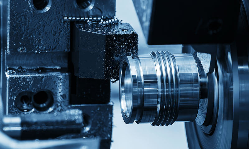
CNC Turning är en bearbetningsprocess där arbetsstycket roterar (den primära rörelsen) och ett enpunkts skärverktyg rör sig linjärt (matningsrörelsen).
Svarven är verktygsmaskinen som används för svarvning. När arbetsstycket snurrar, verktyget tar bort material för att skapa cylindriska profiler, inslag, avtagande, trådar, och andra rotationsfunktioner.

Varför vända Excel:
Svarvning erbjuder exceptionell precision för roterande delar på grund av processens inneboende stabilitet.
Det roterande arbetsstycket säkerställer att alla funktioner är koncentriska mot samma axel, vilket gör det enkelt att uppnå utmärkt koaxialitet och vinkelräthet mellan ytorna.
Skärningsprocessen är kontinuerlig (inga avbrott), möjliggör höga skärhastigheter, Utmärkt ytfinish, och lång livslängd.
| Parameter | Typiskt sortiment | Anteckningar |
| Ytråhet | Ra 0.1 - 3.2 um | Diamantsvarvning av icke-järnmetaller kan uppnå Ra <0.1 um. |
| Dimensionell noggrannhet | ±0,01 – 0.05 mm | Precisionssvarvar kan uppnå ±0,005 mm. |
| Typmaterial | Metaller, plast, kompositer | Inte lämplig för mycket hårda material (>Hrc 60) utan specialverktyg. |
Ansökningar:
- Cylindriska delar: axlar, stift, rullar
- Skivformade delar: flänsar, växlar, svänghjul
- Gängade komponenter: bultar, skruv, nötter
- Excentriska och icke-runda delar (på kamsvarvar)
Maskintyper:
- Horisontella svarvar: Den vanligaste typen; hanterar ett brett utbud av delstorlekar.
- Vertikala svarvar: Används för stora, tunga skivformade komponenter (TILL EXEMPEL., bromstrummor, stora växlar).
- schweizisk typ (automatisk) syrer: Perfekt för små, lång, och komplexa delar (TILL EXEMPEL., klockkomponenter, medicinsk utrustning).
- CNC-svarvcentra: Fleraxliga maskiner som kan utföra komplexa operationer (vändning, fräsning, borrning) i en uppsättning.
Praktiskt tips: Svarvning är den valda processen för alla delar med en dominerande rotationsaxel. För produktion med hög volym, CNC-svarvar med stångmatare kan köras obevakat i timmar.
Fräsning: Den mångsidiga allroundaren
Arbetsprincip:
CNC -fräsning använder en roterande flertandsskärare (den primära rörelsen) för att ta bort material från ett stationärt eller rörligt arbetsstycke.
Skäraxeln är vanligtvis vinkelrät mot arbetsstyckets yta (ändfräsning) eller parallellt med det (perifer fräsning).
Fräsning kan ge plana ytor, slots, fickor, konturer, och komplexa 3D-former.

Varför fräsning Excels:
Fräsning är den mest mångsidiga bearbetningsprocessen. Med rätt fräs och inställning, den kan bearbeta nästan alla funktioner på ett arbetsstycke: platta ytor, spår, profiler, hålrum, och även komplexa 3D-ytor.
Den intermittenta skärverkan, samtidigt som den genererar en del vibrationer, möjliggör höga metallavverkningshastigheter.
Åtskillnad: Up Milling vs. Nedfräsning:
| Frästyp | Skärande | Bäst för | Verktygsliv |
| Upp fräsning (Konventionell) | Spåntjockleken ökar från noll till max. | Äldre maskiner med backlash; gjutgods och smide med hård hud. | Kortare (på grund av skavning vid ingång). |
| Nedfräsning (Klättra) | Spåntjockleken minskar från maximalt till noll. | CNC-maskiner med glappkompensering; Bättre ytfinish. | Längre (renare ingång; mindre gnuggande). |
Skärningsmetoder:
- Ändfräsning: Fräsaxel vinkelrät mot arbetsstycket; används för slots, fickor, och profiler.
- Periferisk fräsning: Skäraxeln är parallell med arbetsstycket; används för plana ytor.
- Planfräsning: Plattfräs med skär; används för stora plana ytor.
- Flugklippning: Enpunktsverktyg för stora plana ytor; låg produktionshastighet men bra finish.
Ansökningar:
- Platta ytor: övre ansikten, monteringsdynor
- Spår och spår: T-spår, nyckel, laxstjärtar
- Komplexa profiler: växlar, kammar, impeller
- 3D konturer: mögelhåligheter, formytor, flyg-
- Gängfräsning: högkvalitativa trådar i hårda material
Toleranser och ytfinish:
| Parameter | Typiskt sortiment |
| Ytråhet | Ra 0.8 - 6.3 um |
| Dimensionell noggrannhet | ±0,02 – 0.10 mm |
| Precisionsfräsning | ±0,005 – 0.01 mm (med avancerad utrustning) |
Praktiskt tips: Vid fräsning, överväg alltid styvheten i installationen. Lång, smala fräsar kommer att avböjas, leder till dålig ytfinish och felaktigheter. Använd kort, styva verktyg där det är möjligt.
Hyvling: Lågkostnadslösningen för platt yta
Arbetsprincip:
Hyvling är en bearbetningsprocess där ett enpunkts skärverktyg rör sig i en rak linje (den primära rörelsen), skära över ett arbetsstycke som hålls på ett fram- och återgående bord.
Arbetsstycket rör sig förbi det stationära verktyget, som tar bort ett lager material vid varje pass. Verktyget återgår till start utan att skära (tomgångsslag).
Varför hyvla Excel:
Hyvling är en billig lösning för stor bearbetning, platta ytor, speciellt för enstaka delar eller små partier.
Maskinerna är relativt enkla och billiga, och verktyget är grundläggande (HSS -verktyg).
Den långa, raka slag är idealiska för bearbetning av raka ytor som maskinbäddar, vägleder, och stora bottenplattor.
| Parameter | Typiskt sortiment | Anteckningar |
| Ytråhet | Ra 1.6 - 6.3 um | Bra men grövre än fräsning. |
| Dimensionell noggrannhet | ± 0,05 - 0.20 mm | Mindre exakt än fräsning. |
| Produktionsgrad | Låg | Tomgångstakten slösar tid. |
Ansökningar:
- Stor, platta ytor: maskinbaser, sängar, och tabeller
- Raka spår: V-spår, laxstjärtar, nyckel
- Enstaka delar och små batchjobb: reparations- och underhållsarbeten
- Verktygsrum och formtillverkningsapplikationer
Begränsningar:
- Låg produktivitet: tomgångstakten begränsar produktionshastigheterna.
- Låg precision: inte lika exakt som fräsning.
- Begränsade former: kan bara producera platta eller raka linjer.
Praktiskt tips: Hyvling är bäst lämpad för jobb där kostnaden för en fräsmaskin eller installation är oöverkomlig. Det används sällan i högvolymproduktion.
Borrning: Grunden för håltagning
Arbetsprincip:
Borrning är processen att skapa ett runt hål i ett arbetsstycke med hjälp av ett roterande flerpunktsskärverktyg som kallas en borr (eller spiralborr).
Borren roterar (primär rörelse) och matas in i arbetsstycket (matningsrörelse). Skärkanterna vid spetsen tar bort material, medan räfflorna evakuerar spån.
Varför borra Excel:
Borrning är det enklaste och mest ekonomiska sättet att skapa hål i metall.
Det kan utföras på ett brett utbud av verktygsmaskiner: borrpressar, fräsmaskiner, och till och med handövningar. Borrning är vanligtvis det första steget i en sekvens av håltagningsoperationer.
| Parameter | Typiskt sortiment | Anteckningar |
| Hålstorleksintervall | 0.1 - 100+ mm | Små hål kräver speciella mikroborrar. |
| Håldjup | Upp till 10× diameter (standard) | Djupa hål kräver specialverktyg (pistolborrning). |
| Dimensionell noggrannhet | ± 0,05 - 0.2 mm | Borrning är en grovbearbetning; hålen kan vara överdimensionerade. |
| Ytfin | Ra 3.2 - 12.5 um | Relativt dålig jämfört med brotschning. |
Vanliga borrrelaterade operationer:
| Drift | Beskrivning | Ändamål |
| Skurande | Förstorar och avslutar ett befintligt hål till en exakt diameter. | Precisionsdimensionering av hål; förbättrad rundhet och ytfinish. |
| Motborrning | Förstorar den övre delen av ett hål till en större diameter. | Skapar en skuldra för ett skruvhuvud (skruv med insex). |
| Försänkning | Skapar en konisk avsmalning i toppen av ett hål. | För plattskruvar och gradning. |
| Tappning | Kapar invändiga gängor i ett hål. | För gängade fästelement. |
Vanliga borrproblem:
| Problem | Orsaka | Lösning |
| Överdimensionerat hål | Borrwobble; sliten borr; felaktig matning. | Använd en mittborr; kontrollera borruppriktningen; minska foder. |
| Hålplaceringsfel | Arbetsstyckets rörelse; dålig layout. | Säkra arbetsstycket; använd en borrjigg. |
| Gradbildning | Felaktiga borrparametrar. | Använd en gradningsoperation; minska foder vid utgång. |
Praktiskt tips: För precisionshåltagning, börja alltid med en mittborr för att skapa en exakt startpunkt, borra sedan efter storlek, och slutligen ream för den sista dimensionen.
Tråkig: Precisionsutvidgningsprocessen
Arbetsprincip:
Borrning är processen att förstora och förfina ett befintligt hål för att uppnå en exakt storlek, rundhet, och ytfinish.
Borrning utförs på en svarv (med hjälp av en tråkig bar) eller på en tråkig maskin.
Ett enpunktsverktyg matas in i hålet längs axeln, ta bort ett tunt lager av material.
Varför tråkiga Excels:
Borrning är den valda processen för att uppnå hög noggrannhet i håldiametrar, koncentrisitet, och inriktning.
Den kan korrigera positionsfel från tidigare operationer (TILL EXEMPEL., borrning) och är avgörande för stora och djupa hål som inte kan brotschas eller borras exakt.
| Parameter | Typiskt sortiment | Anteckningar |
| Håldiameter | 5 - 500+ mm | Begränsad av diametern på borrstången. |
| Djup | Begränsad av verktygets styvhet. | Djupa hål kräver en stel, välstödd tråkig bar. |
| Dimensionell noggrannhet | ±0,01 – 0.05 mm | Precisionsborrning är mycket exakt. |
| Ytfin | Ra 0.4 - 3.2 um | Mycket bra. |
Ansökningar:
- Exakta hål: lagerhus, motorcylindrar, hydrauliska komponenter
- Justera hål: där flera hål kräver exakt koaxialitet
- Hål med stor diameter: hål för stora för standardbrottschar
- Korrigering av befintliga hål: fixa skadade eller felinriktade hål
Praktiskt tips: Borrstänger måste vara styva; även lätt avböjning kan orsaka prat och inexakthet. Använd kortast möjliga verktygsöverhäng.
Kuggskärning och tandprofilbearbetning
Arbetsprincip:
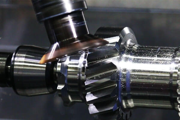
Redskap skärning omfattar en rad processer som används för att producera kuggar på kugghjul, spläder, och andra tandade komponenter. De två vanligaste metoderna är hobbing och kugghjulsformning.
- Hobbing: En roterande skärare (hällen) matas över det roterande arbetsstycket, generering av kugghjulen genom en kontinuerlig skärverkan. Hobbing är mycket produktiv och används ofta för cylindriska och spiralformade växlar.
- Gear Shaping: En fram- och återgående fräs med samma kuggprofil som kugghjulet pressas in i arbetsstycket, genererar tänder en i taget. Formningen är långsammare men kan ge inre kugghjul och några intrikata profiler.
Varför Gear Cutting Excels:
Kuggskärningsprocesser är speciellt utformade för att producera exakta, stark, och tystgående kugghjul. De är standardmetoden för tillverkning av de flesta växlar och splines.
Typiskt prestandaområde för kuggbearbetning
| Parameter | Typiskt sortiment | Anteckningar |
| Modul / Diametral tonhöjd | Modul 0,5–20+ | Täcker små precisionsväxlar till stora industriväxlar. |
| Växeldiameter | 10–1000+ mm | Begränsad främst av maskinkapacitet. |
| Tandnoggrannhet | ISO Grade 5–8 | Högre kvaliteter används för precisionsapplikationer. |
| Ytråhet | RA 0,8-3,2 μm | Släta tandytor minskar friktion och driftsljud. |
| Typmaterial | Kolstål, legeringsstål, rostfritt stål, gjutjärn, brons | Materialvalet beror på belastning, hastighet, och miljö. |
Vanliga metoder för skärning och bearbetning av tandprofiler
| Metod | Arbetsprincip | Bästa applikationerna |
| Gear Hobbing | En roterande hällskärare genererar kontinuerligt kugghjul medan arbetsstycket roterar synkront. | Storvolymproduktion av cylindriska kugghjul, spiralformade kugghjul, och industriella transmissionsväxlar. |
| Gear Shaping | En fram- och återgående fräs genererar tänder genom synkroniserad skärrörelse. | Invändiga växlar, spläder, axelväxlar, och komplexa kugghjulsprofiler. |
Uppblåsning |
En brosch med flera tänder tar bort material i ett enda progressivt pass. | Storvolymtillverkning av invändiga växlar, nyckel, och splines. |
| Form fräsning | En formad fräs skär individuella tandutrymmen enligt önskad profil. | Stora växlar, små partier, reparationsarbete, och anpassade redskapsdesigner. |
| Redskapslipning | En slipande efterbehandlingsprocess tar bort små mängder material efter värmebehandling. | Högprecisionshärdade växlar som används inom bilindustrin, flyg, och högpresterande maskiner. |
Praktiskt tips: Gear hobbing är den mest ekonomiska metoden för produktion av högvolymer. Shaping används för invändiga kugghjul och intrikata former.
Slipning: Precisionsfinishingprocessen
Arbetsprincip:
Slipning använder en roterande slipskiva (består av tusentals hårda, skarpa gryn) att ta bort material genom en kombination av skärning, plöjning, och gnugga.
Slipskivan fungerar som ett skärverktyg med flera tänder, men med negativ spånvinkel, resulterar i en mycket smidig, yta med hög precision.
Varför slipning av Excel:
Slipning är den valda processen för att uppnå högsta ytfinish och måttnoggrannhet, speciellt på härdade material (Hrc > 45).
Det kan korrigera värmebehandlingsförvrängningar och producera platt, parallella ytor.
| Parameter | Typiskt sortiment | Anteckningar |
| Ytråhet | Ra 0.05 - 0.8 um | Precisionsslipning kan uppnå Ra <0.05 um. |
| Dimensionell noggrannhet | ±0,001 – 0.005 mm | Slipning är den mest exakta bearbetningsprocessen. |
| Materialets hårdhet | Fram till 70 Hrc | Kan slipa härdat stål, karbider. |
| Typmaterial | Härdade stål, verktygsstål, karbider, keramik | Allt hårt, sprött material. |
Vanliga slipprocesser:
| Typ | Beskrivning | Ansökningar |
| Ytslipning | Slipning av plana ytor. | Forma plattor, maskinbord, verktyg. |
| Cylindrisk slipning | Slipning av yttre cylindriska ytor. | Axlar, stift, lagertidningar. |
| Invändig slipning | Slipning av invändiga cylindriska ytor. | Lagerhus, cylinderhål. |
| Centrumlös slipning | Cylindrisk slipning utan centra. | Skaftproduktion i hög volym. |
| Verktygs- och frässlipning | Slipning av skärverktyg. | Slipningsövningar, pinnfräsar, ramare. |
| Krypmatningsslipning | Djup, malning med långsam matning. | Komplexa profiler i hårda material. |
Praktiskt tips: Slipning genererar betydande värme, som kan orsaka värmeskador (malande bränna) och återstående stress. Använd rikligt med kylvätska och lämpliga slipparametrar.
Formslipning: Profilinriktningen
Arbetsprincip:
Formslipning använder en formad slipskiva eller en CNC-kontrollerad process för att slipa komplex, icke-linjära profiler.
Hjulet är klädt till en specifik kontur, som sedan slipas in i arbetsstycket.
Detta är en förlängning av slipning för specialiserade applikationer där en specifik form eller profil krävs.
Varför Formslipning Excels:
Formslipning kan producera mycket exakt, komplexa profiler i härdade material, med utmärkt ytfinish och måttnoggrannhet.
Det är den valda processen för att forma formar, stansar, och formar.
Ansökningar:
- Mögelhåligheter
- Die profiler
- Komplexa konturer i verktygs- och formtillverkning
- Precisionsprofiler i flyg- och rymdkomponenter
Praktiskt tips: Formslipning är en specialiserad, högkostnadsprocess, motiveras endast där extrem noggrannhet och utmärkt ytfinish krävs.
3. De 5 Särskilda processer: Icke-traditionell bearbetning
Traditionella skärverktyg kämpar – eller misslyckas helt – när de står inför mycket hårda material (verktygsstål, karbider, keramik), komplexa geometrier (djupa hålrum, mikrofunktioner), eller när termisk eller mekanisk skada måste minimeras.
Specialprocesser använder andra energiformer än mekanisk skärning för att avlägsna material, erbjuda lösningar på dessa utmaningar.
Elektrisk urladdningsbearbetning (EDM)
Arbetsprincip:
EDM– även känd som gnistorsion – tar bort material genom en serie snabbt återkommande elektriska urladdningar (gnistor) mellan en elektrod (verktyg) och arbetsstycket.
Gnistorna eroderar små mängder material från både elektroden och arbetsstycket.
Arbetsstycket är nedsänkt i en dielektrisk vätska (TILL EXEMPEL., avjoniserat vatten eller olja) för att kontrollera utsläppet och spola bort eroderade partiklar.

Typer av EDM:
| Typ | Beskrivning | Ansökningar |
| Sinker EDM (Ram EDM) | Elektroden är formad till negativ av den önskade kaviteten. | Mögelhåligheter, dö sjunka, komplexa 3D-håligheter. |
| Edm (WEDM) | En tunn, ständigt rörlig tråd fungerar som elektrod. | Profiler, konturer, precisionsdelar; ämnen för stämplingsformar. |
| EDM med små hål | En elektrod med liten diameter för finborrning, djupa hål. | Kylhål, bränsleinsprutningsmunstycken. |
Varför EDM Excels:
EDM kan bearbeta vilket ledande material som helst, oavsett dess hårdhet. Det kan producera komplexa, intrikata former (inklusive skarpa hörn) med hög noggrannhet och utmärkt ytfinish.
Processen applicerar ingen mekanisk kraft, så att tunnväggiga och ömtåliga delar kan bearbetas utan förvrängning.
| Parameter | Typiskt sortiment | Anteckningar |
| Ytråhet | Ra 0.2 - 3.2 um | Beror på finish; utmärkt för efterbehandling. |
| Dimensionell noggrannhet | ±0,005 – 0.02 mm | Högprecision, speciellt i tråd-EDM. |
| Materialets hårdhet | Fram till 70 Hrc | Praktiskt taget obegränsad för ledande material. |
| Materialets ledningsförmåga | Måste vara elektriskt ledande. | Ej lämplig för keramik, plast, eller glas. |
Ansökningar:
- Formar hålrum och dör
- Injektionsformar för plast
- Flygplansmotorkomponenter
- Medicinsk utrustning
- Komplexa konturer och profiler
Praktiskt tips: EDM är en långsam process, så det används vanligtvis för efterbehandling, inte för grovbearbetning.
Elektrokemisk bearbetning (Ecm)
Arbetsprincip:
ECM är en icke-traditionell bearbetningsprocess som tar bort material genom anodupplösning. Arbetsstycket (anod) och ett format verktyg (katod) är nedsänkta i en elektrolyt.
En hög likström passerar mellan dem, och metalljoner löses upp från arbetsstycket, som sedan förs bort av elektrolytflödet.
Varför ECM Excels:
ECM kan bearbeta hårda och svårbearbetade material utan verktygsslitage och ingen värmepåverkad zon.
Processen är kapabel till höga materialavlägsningshastigheter och kan producera komplexa former med god ytfinish. Den är särskilt lämpad för borttagning av bulkmaterial.
| Parameter | Typiskt sortiment | Anteckningar |
| Ytråhet | Ra 0.2 - 0.8 um | Mycket bra finish. |
| Dimensionell noggrannhet | ± 0,05 - 0.2 mm | Lägre noggrannhet än EDM. |
| Materialets hårdhet | Fram till 70 Hrc | Praktiskt taget obegränsat; materialet måste vara ledande. |
| Materialavlägsningshastighet | Hög | Lämplig för bulkborttagning. |
Ansökningar:
- Jetmotorblad och skovlar
- Pistolpipor (rifling)
- Medicinsk implantat
- Formar för plast
- Hård, komplexa flyg- och rymdkomponenter
Praktiskt tips: ECM är en specialiserad process som kräver betydande investeringar i utrustning och elektrolythantering. Det motiveras av höga produktionsvolymer eller svårigheten med alternativa metoder.
Laserbearbetning
Arbetsprincip:
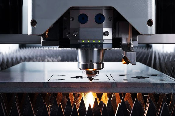
Laserbearbetning använder en starkt fokuserad stråle av koherent ljus (laser) att smälta, förånga, eller avlägsna material från arbetsstycket.
Laserpunkten flyttas över ytan med hjälp av datorstyrda speglar eller rörelsesteg.
Varför laserbearbetning Excels:
Laserbearbetning är en snabb, exakt, och kontaktlös process. Det kan utföras på vilket material som helst (metaller, plast, keramik, glas, kompositer) och kan uppnå extremt fina funktioner (ner till några mikron).
Processen genererar inga mekaniska krafter, så att tunna och ömtåliga delar kan bearbetas.
| Parameter | Typiskt sortiment | Anteckningar |
| Skärbredd | 0.02 - 0.2 mm | Mycket smala snitt. |
| Skärhastighet | Fram till 50 m/min | Hög för plåtmaterial. |
| Funktionsstorlek | Ner till 10 um | För mikrobearbetning. |
| Material | Praktiskt taget vilket material som helst | Metaller, plast, keramik, glas. |
| Noggrannhet | ±0,01 – 0.05 mm | Högprecision. |
Ansökningar:
- Skärande: plåt, profiler, rör
- Borrning: precisionshål, kylhål
- Gravyr och märkning: delnummer, logotyper
- Mikrobearbetning: medicinska stentar, mikroelektronik
- Ytstruktur: skapar mikrosträvhet
Praktiskt tips: Laserbearbetning genererar en värmepåverkad zon (Had). För material som är känsliga för värmeskador, överväg att använda kortpuls (pikosekund/femtosekund) lasrar.
Ultraljudsbearbetning (USM)
Arbetsprincip:
Ultraljudsbearbetning använder ett verktyg som vibrerar med hög frekvens (20-40 khz) och amplitud (10-50 um).
En slipande slurry (TILL EXEMPEL., borkarbid eller kiselkarbid i vatten) införs mellan verktyget och arbetsstycket.
Det vibrerande verktyget slår de abrasiva partiklarna mot arbetsstycket, avlägsnande av material genom mikroflisning och erosion.
Varför USM Excels:
USM är den valda processen för att bearbeta hårda och spröda material som är svåra eller omöjliga att bearbeta med traditionella metoder.
Det är särskilt effektivt för icke-ledande material (keramik, glas, stenar) och material med låg elektrisk ledningsförmåga.
| Parameter | Typiskt sortiment | Anteckningar |
| Ytråhet | Ra 0.2 - 1.6 um | Bra finish. |
| Dimensionell noggrannhet | ±0,005 – 0.02 mm | Högprecision. |
| Material | Hård, spröd, icke-ledande material | Keramik, glas, stenar, karbider. |
| Verktygsslitage | Måttlig | Verktygen slits av de slipande partiklarna. |
Ansökningar:
- Borra hål i keramik och glas
- Bearbetning av avancerade kompositer
- Sjunker i hårda material
- Halvledare och elektronikkomponenter
Praktiskt tips: USM är en långsam process, så det är vanligtvis begränsat till högvärdiga eller svårbearbetade delar.
Vattenstrålebearbetning
Arbetsprincip:
Vattenstrålebearbetning använder en högtrycksström av vatten (med eller utan slipande partiklar) att erodera och skära material. Trycken kan variera från 2,000 till 6,000 bar (30,000 till 90,000 psi).
Vattnet tvingas genom en öppning med liten diameter, skapa en överljudsstråle som påverkar arbetsstycket.
Varför Waterjet Excels:
Vattenstrålebearbetning är en kallskärningsprocess – det finns ingen värmepåverkad zon, ingen termisk distorsion, och inga metallurgiska förändringar.
Det kan skära ett brett utbud av material, inklusive metaller, plast, glas, kompositer, och till och med mat.
Processen är mycket flexibel, kan börja var som helst (inget pilothål krävs), och ger en slät, exakt kant.
| Parameter | Typiskt sortiment | Anteckningar |
| Skärtjocklek | Fram till 200+ mm | Beroende på material och slipmedel. |
| Skärbredd | 0.5 - 1.5 mm | Smal. |
| Skärtolerans | ± 0,05 - 0.2 mm | Bra noggrannhet. |
| Ytfin | Ra 0.8 - 6.3 um | Bra finish. |
| Ingen värmepåverkad zon | Ja | Inga termiska skador. |
Ansökningar:
- Tjocka metallplåtar: aluminium, rostfritt stål, titan
- Spröda material: sten, glas, keramik
- Kompositer: laminerade material (ingen delaminering)
- Matbearbetning: skära livsmedelsprodukter
- Flyg-: komplexa former i avancerade material
Praktiskt tips: Vattenstrålebearbetning är en kraftfull och flexibel process, men det är relativt långsamt och genererar en stor mängd buller och avfallsslam.
Den är bäst lämpad för tjocka eller svårklippta material där andra processer skulle orsaka värmeskador.
4. Tekniska riktlinjer för val av bearbetningsmetoder
Det finns ingen universellt perfekt bearbetningsprocess. Det optimala valet beror på:
- Materialegenskaper.
- Delens geometri.
- Produktionsvolym.
- Noggrannhetskrav.
- Ytfinishkrav.
- Tillverkningskostnad.
| Ansökan | Rekommenderad process | Varför? |
| Roterande delar (axlar, stift) | Vändning | Utmärkt för cylindriska former; bra ytfinish och noggrannhet. |
| Platta ytor, slots, fickor | Fräsning | Mycket mångsidig; kan producera ett brett utbud av former. |
| Stor, platta ytor (enstaka delar) | Hyvling | Låg kostnad för enkla delar; bra för reparation och underhåll. |
| Exakta hål | Borrning + Brotschande eller tråkigt | Borrning för grovt hål; brotschning/borrning för slutlig storlek och noggrannhet. |
| Kugghjulständer | Hobbing, Formning | Högvolymproduktion; standardiserade processer. |
Härdade material (Hrc > 45) |
Slipning eller EDM | Slipning för plana ytor; EDM för komplexa former. |
| Komplexa 3D-håligheter | EDM eller fräsning (5-axel) | EDM för djup, intrikata former; 5-axelfräsning för större delar. |
| Mycket hård, icke-ledande material | Ultraljudsbearbetning | Keramik, glas, stenar. |
| Termiskt känsliga material | Vattenstrålebearbetning | Ingen värmepåverkad zon; minimal distorsion. |
| Högprecision, små funktioner | Laserbearbetning | Mycket fina funktioner, snabb, kontaktlöst. |
5. Slutsats
Bearbetningsvärlden är enorm och komplex, men i dess kärna, den bygger på tre grundläggande principer för materiell omvandling – bildning, avlägsnande, och tillägg – och en uppsättning väldefinierade processer som kan matchas till specifika delkrav.
De 8 traditionella processer — svarvning, fräsning, hyvling, borrning, tråkig, skärning av kugghjul, slipning, och formslipning — utgör stommen i tillverkningsindustrin.
De är arbetshästarna som producerar de allra flesta precisionskomponenter, från enkla stift till komplexa formar och stansar. Deras styrka ligger i deras mångsidighet, noggrannhet, och tillförlitlighet.
De 5 speciella processer – EDM, Ecm, laserbearbetning, ultraljudsbearbetning, och vattenstrålebearbetning – ger kraftfulla alternativ när traditionella skärverktyg når sina gränser.
De möjliggör bearbetning av mycket hårt, spröd, eller komplexa material, och de kan uppnå egenskaper som skulle vara omöjliga med konventionella metoder.
Nyckeln till framgångsrikt processval ligger i att förstå materialet, geometrin, produktionsvolymen, och den tolerans som krävs.
Genom att behärska egenskaperna och tillämpningarna för varje process, Tillverkningsingenjörer kan optimera produktionseffektiviteten, minska kostnaderna, och uppnå överlägsen kvalitet.

