

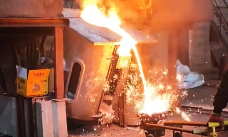
Electric melting furnaces—especially medium-frequency induction furnaces—give foundries excellent control over melting temperature, charge composition, and production flexibility. But the furnace itself is only one part of the ливење систем.
A problem in charge preparation, хемија топљења, slag control, furnace lining, инокулација, spheroidization, or pouring practice can eventually show up as a casting defect, machining problem, unstable microstructure, or excessive production cost.
From a foundry engineer’s perspective, many “casting defects” are actually created before the metal ever reaches the mold.
This is particularly true when producing сиво гвожђе, дуктилни гвожђе, and other ferrous castings in electric melting systems.
The following 15 issues cover the most common furnace and melt-related problems, together with practical corrective measures.
1. Excessive Element Burn Loss
In electric furnace melting, претерано element burn loss is one of those problems that looks small at first but eventually shows up in the chemical analysis, микроструктура, and mechanical properties of the casting.
Elements such as И, Мн, and Cr are susceptible to oxidation during melting, and the actual recovery can vary significantly with charge condition and furnace practice.
In some foundry operations, losses of several percent may be observed, but the exact value is process- and alloy-dependent and should be established from actual furnace data rather than treated as a fixed rule.
After years around induction furnaces, I have found that excessive burn-off usually does not come from one dramatic mistake.
Чешће, the melt simply spends too much time hot and exposed, while the charge and slag practice are not well controlled.
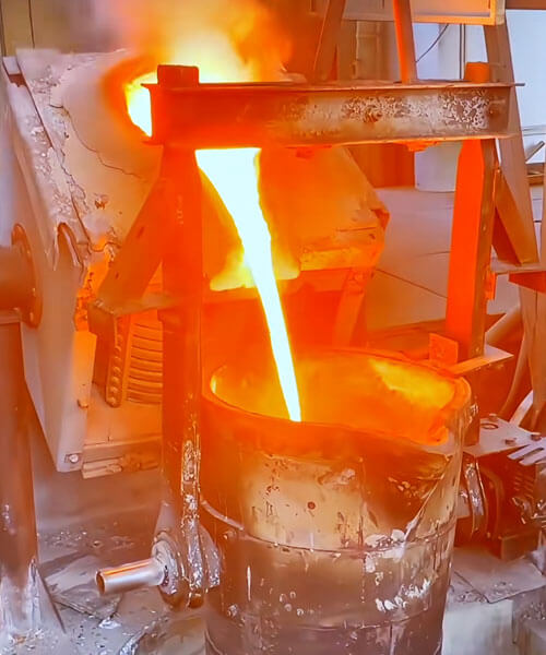
Why Does Excessive Burn Loss Occur?
The first culprit is usually long melting time. The longer the metal remains at elevated temperature, the more opportunity there is for oxidation and element loss.
This becomes worse when the furnace develops bridging or “hanging” charge, because the lower part of the bath becomes overheated while waiting for the remaining charge to collapse.
The condition of the charge also matters. Wet, rusty, heavily oxidized, врло танак, or poorly prepared scrap has a much larger exposed surface area relative to its mass and can increase oxidation and slag formation.
Oversized pieces create another problem: they slow melting and extend the time that the furnace operates before the bath becomes fully molten.
Slag management is equally important. A properly controlled slag layer can reduce direct exposure of the molten metal to the atmosphere.
If slag is allowed to accumulate excessively, међутим, it can also trap valuable metal and alloying elements.
The point is not simply to have more slag, but to maintain the right slag condition at the right stage of melting.
How to Reduce Element Burn Loss
The most effective solution is to control the entire melting cycle, beginning with the charge.
Charge materials should be clean, осушити, and reasonably sized. Avoid excessive amounts of very thin scrap, heavily rusted material, or awkward shapes that are likely to bridge inside the furnace.
The charge should melt progressively and consistently rather than forming a suspended layer above an overheated bath.
The second rule is melt as efficiently as practical. Once the material is molten, unnecessary holding at high temperature should be avoided.
Good furnace loading, stable electrical operation, and timely feeding of the remaining charge all help shorten the melting cycle.
Slag practice also matters. Slag should be managed during the melt rather than allowed to build up uncontrolled.
Где је прикладно, maintaining a controlled slag cover during later stages of melting can help limit direct metal exposure.
For machining chips or fine returns that must be recycled, charging needs more attention because of their large surface-to-volume ratio.
Чист, dry chips can be introduced progressively after a stable molten pool has been established rather than dumped in one large batch.
A Foundry Engineer’s Practical View
When the spectrometer shows that И, Мн, or Cr recovery is consistently lower than expected, I would not immediately compensate by adding more alloying elements.
Прво, look at the melting record:
Charge condition → Melting time → Bath temperature → Holding time → Slag condition → Actual element recovery
Once the foundry knows its real recovery rate, charge calculations become much more reliable.
The important point is that excessive burn loss is usually a process-control problem before it is a chemistry-adjustment problem.
Reduce unnecessary high-temperature exposure, improve charge preparation, prevent bridging, and maintain controlled slag protection.
The result is not only more stable chemistry, but also more consistent casting structure and mechanical performance.
2. Excessive Oxygen in the Molten Iron
In induction-furnace melting, excessive oxygen is not usually as obvious as a temperature problem or a chemistry deviation.
Међутим, when oxygen activity becomes too high, it can affect slag formation, растопити чистоћу, graphite nucleation, and the consistency of the final microstructure.
From a foundryman’s point of view, the first thing to remember is that an induction furnace does not have the same strongly oxidizing atmosphere associated with some other melting systems.
So when oxygen problems appear, I usually look first at how the melt was handled, especially during the later stage of melting.
Why Does Oxygen Become Excessive?
One common cause is excessive electromagnetic stirring or overly aggressive frequency adjustment late in the melt.
Strong bath movement increases the contact between molten metal and the atmosphere, giving oxygen more opportunity to enter the melt.
Another common cause is wet or poorly prepared additions.
Влага, хрђа, and surface oxides on late-added materials can increase oxide formation and introduce additional gas-related problems.
Long periods of overheating or holding at high temperature can also make the situation worse.
The longer the melt remains exposed under these conditions, the greater the opportunity for oxidation and slag formation.
The important point is that oxygen control is not simply a matter of measuring one number. Температура, време задржавања, узнемиреност, charge condition, and slag practice all interact.
How to Control Excessive Oxygen
During the later stage of melting, avoid unnecessary agitation once the required chemistry and temperature have been reached.
Do not keep the bath moving simply because the furnace is capable of doing so.
All additions, алата, and charge materials that come into contact with the melt should be clean and dry.
This is particularly important for late chemistry adjustments, because there is little time left to correct any additional contamination before pouring.
High-temperature holding should also be minimized. Bring the melt to the required temperature, complete the necessary chemical adjustment and treatment, and move toward pouring rather than maintaining an unnecessarily hot bath.
For critical production, direct analysis of oxygen and other dissolved gases can be more useful than relying only on visual observation of the melt.
A Foundry Engineer’s Practical View
When oxygen-related casting problems appear, I would not immediately blame the furnace itself.
I would first review the late-stage melting practice:
Agitation → Addition materials → Temperature → Holding time → Slag condition
У многим случајевима, excessive oxygen is not caused by the melting principle of the induction furnace, but by what happens after the metal is already molten.
3. Carbon Content Lower Than Expected
Another common problem in electric-furnace melting is that the final carbon content comes out lower than the charge calculation predicts.
This is especially troublesome in gray iron and ductile iron because carbon is not simply an alloying number on the analysis report.
It directly influences the carbon equivalent, Графитно стварање, Понашање учвршћивања, feeding characteristics, and final microstructure.
A common mistake is to calculate the charge correctly on paper and assume the calculated carbon content will appear automatically in the final melt. У стварној производњи, the furnace always has its own carbon recovery behavior.
Why Does Carbon Fall Below Target?
One reason is excessive temperature and prolonged holding. Under certain furnace conditions, carbon can be consumed through oxidation and high-temperature reactions.
The chemistry of the slag and furnace atmosphere also matters. When the melt is held too hot for too long, the effective carbon recovery can decrease.
Another practical cause is simply using a theoretical carbon recovery value that does not match the actual furnace.
Every shop has differences in furnace design, charge materials, operating practice, and melting time.
A recovery factor taken from a handbook may therefore be quite different from the value seen on the shop floor.
How to Prevent Low Carbon
The first step is to establish the foundry’s actual carbon recovery rate from production data.
Record the calculated charge carbon, final spectrometer result, melting time, историја температуре, and charge composition over a series of heats.
After enough data have been collected, the real recovery behavior becomes much clearer.
Charge calculations should then be corrected using this plant-specific recovery factor rather than relying entirely on theoretical values.
Avoid unnecessary overheating and prolonged high-temperature holding.
The target is to achieve the required melt condition efficiently and proceed to treatment and pouring without spending additional time at temperature.
For chemistry adjustments, carbon addition should also be introduced using a controlled method that promotes reliable dissolution and minimizes oxidation losses.
A Foundry Engineer’s Practical View
When final carbon repeatedly comes out below target, I normally check four things first:
Charge calculation → Actual carbon recovery → Melting/holding temperature → Carbon addition practice
Once the actual furnace recovery is understood, the problem becomes much easier to control.
Stable carbon is one of the foundations of stable gray and ductile iron production, and in my experience, good furnace records are far more reliable than repeatedly correcting the melt by guesswork.
4. Nitrogen-Related Pinholes and Fissure-Like Gas Defects
Gas-related defects that only become visible after machining are particularly troublesome.
The casting may look sound on the outside, but once a bore, sealing surface, or other section is machined, мали pinholes or fissure-like cavities suddenly appear.
In iron foundries, претерано азот can contribute to this type of defect under susceptible process conditions. Међутим, nitrogen is rarely the only factor.
Растопљена чистоћа, оксидне инклузије, charge materials, водоник, услови изливања, and graphite nucleation all influence the final result.
Why Does It Happen?
The problem usually starts with the charge. Some alloy steels and certain scrap materials can carry relatively high nitrogen levels.
If these materials are mixed into a normal iron charge without control, the nitrogen content of the melt can gradually increase.
Carburizers also deserve attention. Two products that both look like “carbon raiser” on the purchasing sheet can have very different nitrogen contents.
That difference may not matter on paper, but it can matter considerably in a sensitive iron grade.
Another point I would emphasize from experience is that low nitrogen is not automatically the target for every cast iron.
Nitrogen can influence graphite nucleation and matrix development, so the correct value depends on the grade and the required microstructure. The objective is a controlled nitrogen level, not simply the lowest possible number.
How to Prevent It
Start with charge control. Avoid uncontrolled high-nitrogen scrap and verify the composition of carburizers when nitrogen-sensitive products are being produced.
If the casting is showing unexplained pinholes, direct oxygen/nitrogen analysis is much more useful than continuing to change the inoculant blindly.
The foundry should compare the nitrogen level of a good heat with that of a defective heat and then trace the difference back to the charge and process.
Nitrogen-binding additions such as Ti or Zr can be used in selected processes, but they should not be treated as a universal cure because they can also change inclusions and microstructure.
A Foundry Engineer’s Practical View
When fissure-like gas defects suddenly appear, I usually check:
Charge → Carburizer → Total N/O → Melt cleanliness → Pouring practice
Find the source before trying to “fix” the symptom.
5. Poor Inoculation Response in Gray Iron
Induction melting is efficient and clean, but one side effect is that the final melt can have a relatively low sulfur and oxygen potential compared with some traditional melting routes.
Под овим условима, gray iron may respond poorly to inoculation, even when the operator increases the inoculant addition.
You may see higher undercooling, less favorable flake graphite morphology, more carbide tendency in thin sections, or simply a casting structure that is less stable than expected.
Why Does Inoculation Become Ineffective?
Inoculation does not work independently of the base iron. Its effectiveness depends on the chemistry and metallurgical state of the melt, as well as the type, amount, and timing of the inoculant.
A very low sulfur level can be part of the problem in some gray-iron processes.
Different foundries use different target ranges, but for many practical gray-iron operations the sulfur level is intentionally controlled rather than allowed to fall to an extremely low value.
The other problem is inoculation fading. An inoculant added too early can lose much of its effect before the metal reaches the mold.
How to Improve the Response
First stabilize the base iron. Do not try to solve an unstable melt simply by increasing inoculant addition.
Then select the inoculant according to the grade and process and add it as close to pouring as practical.
Common FeSi-based inoculants may contain controlled additions such as Ca, Балазан, Ср, or rare earths to promote effective graphite nucleation.
If the shop repeatedly experiences poor response, compare sulfur, oxygen activity, undercooling, inoculation addition, and fading time between good and bad heats.
That usually tells you more than simply looking at inoculant consumption.
A Foundry Engineer’s Practical View
When an operator tells me, “We added more inoculant, but it still did not work”, my first question is:
What was the condition of the base iron before inoculation?
Inoculation is a finishing operation. It cannot compensate for unstable melt quality.
6. Unstable Nodularity in Ductile Iron
In ductile iron production, nodularity fluctuations are a classic sign that the base iron and treatment process are not sufficiently stable.
One heat may produce clean, well-formed graphite nodules, while the next shows lower nodularity, more irregular graphite, or an entirely different graphite population even though the operator followed the same treatment recipe.
Why Does Nodularity Change?
The first thing I check is the initial sulfur content.
Magnesium is consumed during spheroidization, and the amount required depends strongly on the sulfur and oxygen condition of the untreated iron.
If the sulfur level varies from heat to heat, a fixed magnesium addition will not produce a fixed residual Mg level.
Температура третмана, magnesium recovery, reaction intensity, инокулација, and the time between treatment and pouring also affect the result.
Charge segregation is another practical issue. Gray-iron returns, ductile-iron returns, легура челика, and other scrap should not be mixed without considering their influence on chemistry.
How to Stabilize Nodularity
The key is to control the complete treatment chain:
Base-Iron Chemistry → Sulfur → Treatment Temperature → Magnesium Recovery → Inoculation → Pouring Time
For many ductile iron grades, residual Mg may fall broadly around 0.03–0.06 wt.%, but this is only a general reference.
The correct target must be established for the specific grade, дебљина секције, treatment method, и спецификација купца.
Metallographic control should also go beyond a simple “nodularity percentage”.
Nodule count, size distribution, графитна морфологија, matrix structure, and carbide content provide a much better picture of whether the process is actually stable.
A Foundry Engineer’s Practical View
If nodularity keeps moving around, do not immediately change the magnesium addition.
First stabilize the base iron. A consistent treatment applied to inconsistent metal will still produce inconsistent castings.
7. Low Graphite Nodule Count and Uneven Nodule Size
A ductile iron casting can have acceptable graphite nodularity and still have an unsatisfactory nodule count or size distribution.
This distinction matters. Nodularity tells us how round and well-formed the graphite is; nodule count tells us how many graphite particles formed during solidification. Both influence solidification behavior and the final matrix structure.
Common Causes
When residual magnesium is adequate but nodule count is low, I would first suspect poor or fading inoculation.
Inoculation creates additional graphite nucleation sites. If the inoculant is added too early, is poorly dissolved, or is not well matched to the iron condition, the effect can fade before the metal reaches the mold.
Cooling conditions also matter. A thick section solidifies more slowly than a thin section, so the same treatment can produce different nodule populations in different parts of the same casting.
How to Improve Nodule Count
Use a stable inoculation practice and pay close attention to timing.
For wire-treated ductile iron, inoculation is generally performed immediately after the spheroidization treatment or with only a short controlled delay, у зависности од процеса.
For some ductile iron applications, nodule counts of 100–200 nodules/mm² or higher may be encountered, but there is no universal “correct” value.
The target depends on alloy composition, дебљина секције, брзина хлађења, and the applicable specification.
The important thing is доследност, not chasing a single number.
A Foundry Engineer’s Practical View
If the graphite is round but too coarse and too sparse, the first question should not be “Do we need more magnesium?"
It is usually more useful to ask:
Was the iron properly inoculated, and was that inoculation still effective when the metal entered the mold?
Good ductile-iron production depends on controlling both spheroidization and nucleation. One without the other is not enough.
8. Poor Machinability After Casting
When a customer says, “The casting is difficult to machine," I do not automatically blame the CNC process.
У многим случајевима, the real problem was already created in the melt and solidification stages.
Cast iron can machine very differently even when two heats have similar hardness values.
The actual cutting behavior depends heavily on matrix structure, графитна морфологија, карбиди, phosphides, инклузије, and local chill.
Typical causes include free cementite, hard phosphide or carbide phases, excessive pearlite in a grade intended to be more ferritic, abnormal structures in thermal hot spots, or undissolved ferroalloy particles.
Why Does It Happen?
A section that cools rapidly can develop chilled iron or carbide-rich areas, while a hot spot may develop a different matrix from the surrounding metal.
In ductile iron, excessive pearlite or carbides can also increase tool wear and cutting forces.
This is why simply checking Brinell hardness is not always enough.
Two castings with similar hardness can have noticeably different machinability because the microstructure and hard-phase distribution are different.
How to Improve Machinability
The solution starts upstream:
Charge Chemistry → Carbon Equivalent → Inoculation → Solidification Rate → Heat Treatment → Final Microstructure
Control the chemistry first, then examine the graphite and matrix structure.
If the machining problem occurs only in thin sections or near hot spots, the mold design and cooling conditions may need attention rather than another change to the CNC cutting parameters.
Где је потребно, metallographic examination can quickly reveal whether the real problem is cementite, карбиди, excessive pearlite, graphite abnormality, or another microstructural issue.
A Foundry Engineer’s Practical View
When machining suddenly becomes difficult, I always ask:
“Did the metal structure change?"
If the tool wear increased at the same time as casting hardness or microstructure changed, the machining shop may only be seeing the final symptom of a foundry problem.
9. Residual Magnesium Appears Too High by Spectrometer
Sometimes the spectrometer reports a relatively high residual magnesium вредност, yet the casting does not show the expected chill or abnormal microstructure.
This is a situation where I would check the measurement before changing the treatment process.
For some ductile iron grades, residual Mg around 0.03–0.06 wt.% can be reasonable, but the correct target depends on the grade, sulfur level, treatment method, Величина секције, и спецификација.
Why Can the Result Be Misleading?
Several factors can affect spectrometer readings:
- Instrument calibration or drift
- Incorrect reference standards
- Poor sample preparation
- Inconsistent grinding
- Површинска контаминација
- Non-representative sampling
Magnesium is also sensitive to analytical technique, so the operator’s sample preparation and testing practice matter more than many people realize.
How to Verify the Result
The first step is to check the instrument with a certified reference standard.
Sample preparation should follow a controlled procedure, including proper grinding and a clean, representative surface.
If the result remains questionable, compare it with an independent analytical method such as wet chemical analysis где је прикладно.
A Foundry Engineer’s Practical View
When the chemistry report and the casting structure seem to disagree, do not immediately change the furnace recipe.
First prove that the measurement is right.
I have seen shops chase magnesium, угљеник, and silicon adjustments for an entire shift when the real problem was a poor sample or an incorrectly calibrated spectrometer.
10. Low Impact Toughness in Ductile Iron
A ductile iron casting can pass its tensile-strength requirement and still fail an impact test.
This is particularly important for grades where toughness and ductility are specified in addition to strength.
Impact performance is influenced by chemical composition, графитна морфологија, matrix structure, carbide content, инклузије, and casting quality.
Why Does Impact Toughness Fall?
High levels of phosphorus and manganese can be detrimental to ductility and impact performance in ferritic ductile iron, while excessive pearlite, карбиди, poor nodularity, or unfavorable graphite morphology can also reduce toughness.
For a grade such as QT350-22L or QT400-18L, the objective is not simply to maximize strength.
The chemistry and treatment must be balanced to obtain the required ferritic matrix and ductility.
How to Improve It
Start with clean and controlled charge materials. Avoid unnecessary alloy contamination and keep phosphorus and manganese within the specified range.
Then control the complete melt-treatment sequence:
Base Iron → Spheroidization → Inoculation → Solidification → Matrix Control
For critical grades, metallographic examination should be used alongside tensile and impact testing.
If impact values suddenly fall, compare the failed heats with an accepted heat rather than looking only at the final impact number.
A Foundry Engineer’s Practical View
When impact toughness is low, do not simply add alloy to increase strength.
A casting can become stronger and still become more brittle.
I always look at the matrix first—ferrite, бисер, карбиди, and graphite morphology—then work backward to the chemistry and treatment process.
The right question is not “How do we make it harder?” but “What microstructure did we actually produce?"
11. Unexplained Casting Problems
Every foundry eventually encounters the most frustrating sentence on the shop floor:
“Nothing changed, but the casting is different.”
When the obvious parameters appear unchanged but porosity, graphite structure, тврдоћа, обрада, or mechanical properties suddenly shift, continued guesswork usually wastes time.
The first step is to compare a good heat and a bad heat using actual measurements.
Useful Diagnostic Methods
Depending on the defect, useful tools include:
- Оптичка емисиона спектроскопија for major and trace elements
- Oxygen/nitrogen analysis for dissolved-gas and cleanliness problems
- Металографија for graphite and matrix evaluation
- SEM/EDS for inclusions and abnormal phases
- Рендген или ЦТ for internal porosity and defects
- Thermal analysis for solidification behavior
- Ултразвучно тестирање for suitable internal discontinuities
The key is to select the test according to the suspected mechanism. There is little value in performing every available analysis without a clear diagnostic question.
A Foundry Engineer’s Practical View
When the cause is unclear, I do not believe in changing three things at once.
Change one controlled variable, compare it with a known good heat, and keep the production records.
Good casting vs. bad casting is often the fastest route to the answer.
If the foundry cannot perform the required analysis internally, sending samples to a qualified laboratory is usually cheaper than scrapping another week of production.
12. Long Melting Time and Excessive Electricity Consumption
Long melting cycles are more than an energy problem.
The longer the metal stays in the furnace, the more opportunity there is for oxidation, alloy loss, slag formation, refractory attack, and unnecessary temperature rise.
From a production standpoint, a slow furnace also reduces available melting capacity and increases the cost per tonne of acceptable metal.
Why Does Melting Take Too Long?
The causes can be surprisingly simple:
- Poorly prepared or oversized charge
- Charge bridging
- Low charge density
- Inefficient electrical transmission
- Poor furnace condition
- Unnecessary high-temperature holding
- Cooling-system or electrical-system problems
- Worn refractory or inefficient operating practice
Specific energy consumption varies significantly with furnace design and plant conditions, so published values should be treated carefully.
A figure such as 570 kWh/t or 800 kWh/t is not a universal benchmark. The useful number is the actual kWh per tonne of acceptable molten metal produced in that specific plant.
How to Reduce Energy Consumption
Start by shortening the complete melt cycle rather than simply increasing furnace power.
Charge material should be dry, чист, appropriately sized, and packed efficiently. Bridging should be prevented, and unnecessary holding at high temperature should be eliminated.
The electrical system also needs to be checked as a complete chain:
Incoming Power → Converter → Capacitors → Cables/Busbars → Induction Coil → Furnace → Molten Metal
Energy can be lost at several points.
Furnace condition matters as well. A deteriorated lining, inefficient cooling system, or electrical fault can quietly increase energy consumption for every heat.
A Foundry Engineer’s Practical View
When someone tells me, “The furnace is running at full power, so it must be efficient," I am not convinced.
I want to see three numbers:
Melting time + kWh/t + tonnes of acceptable metal
A furnace that melts fast but produces unstable metal is not efficient. A furnace that uses less electricity but takes too long may have the same problem from another direction.
The real target is stable chemistry, predictable melting time, and the lowest practical energy consumption per tonne of good castings.
13. Frequent Furnace Electrical and Mechanical Failures
An electric melting furnace is the center of the foundry’s production process, so even a seemingly minor electrical or mechanical fault can quickly stop the entire line.
У пракси, many repeated furnace failures are not caused by the furnace body itself, but by power electronics, Расхладни системи, Хидрауличне компоненте, сензори, везе, and control components.
Typical trouble areas include the converter and control boards, кондензатори, water-cooling circuits, coil connections, hydraulic systems, temperature monitoring, leakage protection, и изолација.
Why Does It Happen?
Poor component quality is one cause, but maintenance is just as important.
Loose electrical connections, unstable cooling-water flow, excessive water temperature, кондензација, or a failed sensor can gradually develop into a much larger failure.
Cooling is particularly critical for induction furnaces. The coil and associated electrical components depend on stable water circulation.
A small cooling-water problem can become a serious safety issue if it is ignored.
How to Prevent It
When purchasing or maintaining an electric furnace, pay attention not only to melting capacity but also to the quality and traceability of key components.
The maintenance program should include routine checks of:
- Cooling-water flow and temperature
- Electrical connections
- Hydraulic pressure
- Coil condition
- Leakage protection
- Изолација
- Alarm and interlock systems
The supplier should also provide clear information about critical spare parts and their replacement cycle.
A Foundry Engineer’s Practical View
When a furnace starts having “small problems” every few days, I never consider them small.
A bad water connection, a weak capacitor, or a faulty sensor can eventually become a production shutdown—or a safety problem.
A good furnace is not the one that works when everything is new.
It is the one that remains stable after thousands of production cycles because its components, одржавање, alarms, and spare-parts system were properly planned from the beginning.
14. Short Furnace Lining Life
The furnace lining is one of the most important components of an induction furnace.
It separates the molten metal from the furnace structure, so lining quality directly affects service life, растопити чистоћу, production stability, and operator safety.
For iron melting, acidic silica-based linings are widely used in appropriate induction-furnace applications.
Међутим, lining life depends on much more than the nominal refractory material.
Why Does the Lining Wear Too Quickly?
Уобичајени узроци укључују:
- Poor refractory quality
- Incorrect particle-size distribution
- Improper installation or compaction
- Inadequate sintering
- Excessive operating temperature
- Aggressive slag
- Mechanical impact during charging
- Incorrect first-heat practice
Even good refractory material can have a short service life if the installation and sintering process are poor.
The raw material should have a suitable silica content and controlled impurity levels.
For silica refractories, high SiO₂ content—often above 98% for suitable raw materials— can be important, but the exact refractory specification must follow the furnace design and supplier’s technical requirements.
How to Improve Lining Life
The most important step is to match the refractory system to the furnace capacity, легура, радна температура, slag condition, and production cycle.
Installation must follow the refractory supplier’s specified procedure, including proper ramming, сушење, очвршћавање, and first-heat sintering.
The first heat deserves particular attention. A controlled temperature rise and correct sintering process establish the working layer that protects the lining during subsequent production.
Током службе, the lining should be inspected regularly rather than waiting for an obvious failure.
Changes in furnace capacity, bath depth, or lining profile can provide early indications of localized wear.
A Foundry Engineer’s Practical View
I have seen foundries save a little money on refractory and then lose much more through shorter lining life, lost production, and unnecessary repairs.
The cheapest lining is rarely the cheapest lining to run.
Choose the refractory according to the actual furnace and metal being melted, install it correctly, and treat the first heat seriously.
A good lining protects not only the furnace, but also the melt and the people operating it.
15. “Elephant Foot” Refractory Erosion
The so-called “elephant foot” is a characteristic form of localized refractory erosion near the lower part of an induction-furnace lining.
The inner profile becomes locally recessed or enlarged, giving the worn area its distinctive shape.
It is more than a visual defect. Severe localized erosion can reduce effective furnace volume, affect melt cleanliness, accelerate refractory damage, and eventually create a serious safety risk.
Why Does It Develop?
One common cause is unstable charging and bridging.
If oversized charge pieces form a bridge above the molten bath, the lower part of the furnace can become heavily exposed to thermal and mechanical stress.
When the bridge eventually collapses, heavy material can impact the lower lining.
Excessive local temperature and chemical attack can accelerate the erosion.
A lining that is already weakened by poor sintering or inappropriate refractory selection is even more vulnerable.
How to Prevent It
Charge material should be appropriately sized and loaded in a way that avoids unstable bridging. Велики, heavy pieces should not be dropped directly onto the furnace bottom.
The operator should also avoid unnecessary overheating and should monitor the lining profile during routine inspections.
Once localized erosion is observed, repair should be considered before the damaged area develops into a major safety problem.
A Foundry Engineer’s Practical View
When I see an elephant-foot profile, I do not simply ask, “How much lining has been lost?"
I want to know why it happened there.
Was the charge bridging? Was the furnace overheated? Was the lining improperly sintered? Was the refractory unsuitable for the process?
If you only repair the worn area without correcting the cause, the same problem will come back.
In foundry work, lining wear is often a record of how the furnace has been operated.
Read that record carefully, and you can often prevent the next failure before it happens.
16. Закључак
Electric-furnace casting problems are rarely solved by changing one parameter in isolation.
A stable casting process requires control of the complete chain:
Charge Materials → Furnace Operation → Melt Chemistry → Temperature → Slag and Gas Control → Treatment/Inoculation → Pouring → Solidification → Inspection
The most important practical lesson is that melt quality is created before pouring.
Из тог разлога, a modern foundry should not rely on operator experience alone.
Спектрометријска анализа, oxygen/nitrogen measurement, металографија, термичка анализа, НДТ, energy monitoring, and refractory inspection turn furnace control from experience-based troubleshooting into measurable process engineering.
The goal is not simply to produce molten iron.
The goal is to produce clean, хемијски стабилан, thermally controlled metal that solidifies into the specified microstructure and consistently produces castings that meet dimensional, механички, обрада, и захтевима услуге.

