

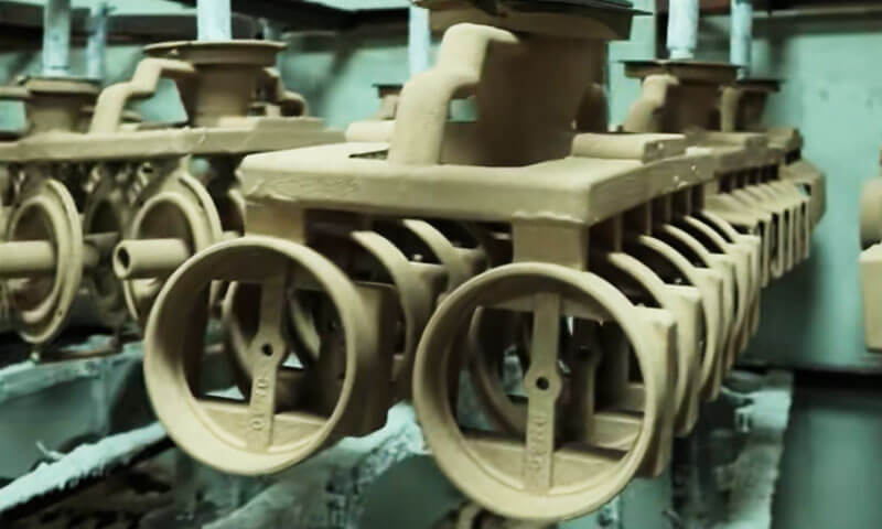
У прецизном ливењу, the gating system is the complete passage that guides molten metal from the ladle or furnace spout into the mold cavity.
The gating system is not just a “pouring channel.” It is the casting’s blood vessel network. It controls flow stability, заробљавање шљаке, евакуација гаса, редослед пуњења, и храњење.
If the gating system is wrong, the casting will show porosity, slag holes, хладноће, проточне линије, мисунс, or shrinkage—no matter how good the rest of the process is.
This guide presents the evaluation criteria I use on the shop floor.
1. What Is a Casting Gating System?
A casting gating system is a network of channels that guides molten metal from the pouring ladle or furnace nozzle into the mold cavity.
It controls how metal enters, flows through, and fills the cavity before solidification begins.
In practical foundry engineering, the gating system functions much like the circulation network of a casting: its design directly affects filling stability, inclusion control, евакуација гаса, услови храњења, и укупан квалитет ливења.
A properly designed gating system does more than deliver sufficient molten metal.
It must regulate flow velocity, минимизирати турбуленције, prevent slag and oxide inclusions from entering the cavity, provide a suitable filling sequence, and avoid prematurely cutting off the feeding path.
These requirements are particularly important in Инвестициони ливење, where the thin ceramic shell must withstand the thermal and mechanical impact of molten metal.
An improperly designed ingate can erode the shell facecoat, introduce ceramic inclusions, or cause localized turbulence.
For sand castings, excessive metal velocity may erode the mold surface, generate sand inclusions, and compromise dimensional accuracy.
From a foundry engineering perspective, four fundamental functions define a gating system:
- Flow stabilization: Deliver molten metal smoothly, without excessive turbulence, прскање, or air entrainment.
- Контрола укључивања: Prevent slag, оксиди, ватросталне честице, and other contaminants from entering the casting.
- Gas evacuation: Allow displaced air and mold gases to escape during filling.
- Controlled filling and feeding: Fill the cavity in a suitable sequence while maintaining the required feeding conditions during solidification.
When these functions work together, the risk of gas porosity, инклузије шљаке, хладноће, мисунс, flow marks, and related casting defects can be substantially reduced.
2. Main Components of a Casting Gating System
A conventional gating system consists of four primary components: базен за изливање, спруе, тркач, и ингате.
Each component has a distinct function, and their dimensions and relative positions must be considered as one integrated system.
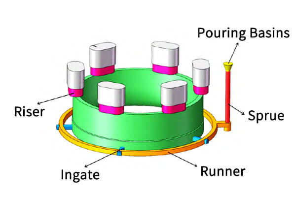
Pouring Basin (Pouring Cup)
The pouring basin receives molten metal from the ladle or furnace and directs it into the sprue. It provides a stable entry point and helps maintain a continuous metal stream during pouring.
Its main functions include:
- Reducing direct impact and excessive splashing as molten metal enters the gating system.
- Maintaining a relatively stable metal head above the sprue entrance.
- Allowing some large floating contaminants to remain near the surface rather than immediately entering the sprue.
- Supporting consistent pouring and reducing the risk of air aspiration.
A poorly designed pouring basin may cause turbulent flow, intermittent metal delivery, and air entrainment.
Its geometry should therefore support smooth flow into the sprue without creating unnecessary restrictions.
Спруе
The sprue is the vertical passage that carries molten metal from the pouring basin to the runner. It establishes the metallostatic head that drives metal through the gating system.
A properly designed sprue is generally tapered, with a larger cross-section at the top and a smaller cross-section toward the bottom.
This geometry helps the sprue remain full during pouring and reduces the risk of air being drawn into the metal stream.
Кључна разматрања дизајна укључују:
- Taper: The cross-sectional area should decrease appropriately along the flow direction to accommodate increasing metal velocity.
- Sprue height: The available metallostatic head influences flow velocity and filling behavior.
- Sprue well: A properly sized sprue well can reduce the impact and turbulence of metal entering the runner.
- Континуитет тока: Sudden changes in cross-section or sharp transitions should be avoided.
An oversized or poorly tapered sprue may encourage air aspiration and unstable flow. An undersized sprue can restrict the metal supply and contribute to incomplete filling.
Руннер
The runner is the horizontal or near-horizontal channel that distributes molten metal from the sprue to one or more ingates.
It also serves as an important location for controlling the movement of slag, оксиди, and other inclusions.
The runner performs three major functions:
- Distributes molten metal to different ingates or mold cavities.
- Helps stabilize the flow before metal enters the casting.
- Provides space and flow conditions that support the separation and retention of certain non-metallic inclusions.
Runner design must account for cross-sectional area, дужина, смер протока, branching geometry, and the position of ingates.
Abrupt changes in direction or section can generate turbulence and increase the possibility of oxide-film formation.
Где је прикладно, екстензије тркача, замке за шљаку, филтри, and other inclusion-control features can improve cleanliness.
Међутим, a runner should not be considered an absolute barrier against all inclusions. Its effectiveness depends on the alloy, Температура изливања, брзина протока, gating geometry, and the nature of the contaminants.
Ingate
The ingate is the final passage through which molten metal enters the mold cavity. It has a direct influence on filling velocity, смер протока, редослед пуњења, and the thermal distribution within the casting.
Unlike the sprue and runner, which mainly transport and distribute metal, the ingate determines how metal interacts with the actual casting geometry.
Important design considerations include:
- Ingate cross-sectional area: Controls the amount and velocity of metal entering the cavity.
- Ingate location: Determines the initial filling region and influences the overall filling sequence.
- Ingate direction: Should avoid direct impact on thin mold sections, језгра, and vulnerable ceramic shell surfaces.
- Ingate thickness: Affects local cooling and the duration of the connection between the casting and gating system.
- Ingate quantity: Multiple ingates may be necessary to distribute metal evenly across large or complex castings.
За сложене ливене ливење, ingates are often positioned near thicker sections or selected regions where metal can enter without damaging the ceramic shell.
Међутим, the final arrangement must balance filling behavior with solidification and feeding requirements.
3. Key Design Principles of an Effective Gating System
A gating system should be evaluated as a complete flow-control and solidification-support system. A design that fills the mold quickly is not necessarily a good design.
Excessive velocity may produce turbulence and inclusions, while insufficient velocity may cause premature freezing and incomplete filling.
The following principles provide a practical framework for gating system design.
Ensure Smooth, Stable Metal Flow
The first requirement is to deliver molten metal into the mold cavity with controlled velocity and minimal turbulence.
Unstable flow can cause several problems:
- Air entrainment and oxide-film formation.
- Splashing and secondary oxidation.
- Mold or ceramic shell erosion.
- Инклузије песка, Керамичке инклузије, и површинских недостатака.
- Uneven filling and localized temperature differences.
У песком ливењу, high-velocity metal can erode the mold surface and carry sand particles into the cavity.
У инвестиционом ливењу, a concentrated metal stream may damage the ceramic facecoat, particularly at sharp corners or thin shell sections.
To improve flow stability, engineers should avoid abrupt cross-sectional changes, unnecessary sharp turns, poorly positioned ingates, and excessive local velocity.
A smooth transition between the sprue, тркач, and ingate helps reduce flow separation and impact.
It is also important to recognize that turbulence is not determined by ingate velocity alone.
Alloy properties, gating geometry, mold layout, pouring height, and the interaction between the incoming stream and cavity walls all influence the actual flow pattern.
Provide Reliable Slag and Inclusion Control
Slag and non-metallic inclusions can significantly reduce casting quality, particularly in components that require pressure tightness, отпорност на умор, or a clean machined surface.
The runner is often the primary location for inclusion-control features because it provides an opportunity to separate contaminants before the metal reaches the ingates.
Common design measures include:
- Providing sufficient runner volume for flow stabilization and inclusion separation.
- Using runner extensions or slag traps to collect contaminants.
- Positioning ingates so that they do not draw floating slag directly into the cavity.
- Applying ceramic foam filters or other suitable filtration methods where required.
- Avoiding excessive pouring turbulence that can break up surface oxides and carry them into the metal.
The effectiveness of slag control depends on the density, величина, and behavior of the inclusions.
Large floating slag particles may be retained relatively easily, while fine oxides and suspended inclusions are more difficult to separate.
Стога, gating design should work together with melt treatment, ladle cleanliness, and pouring practice.
Establish a Rational Filling Sequence
The filling sequence determines how molten metal reaches different areas of the mold. A well-designed system should fill the cavity completely before excessive local solidification prevents further flow.
Several practical guidelines are commonly considered:
- Fill distant regions without leaving them until the end: The gating arrangement should prevent remote or difficult-to-reach sections from becoming isolated.
- Prioritize thin sections where premature freezing is likely: Thin walls lose heat quickly and require sufficient filling temperature and flow capacity.
- Avoid unnecessary flow interference: Multiple streams should not collide in a way that traps air or creates oxide films.
- Maintain adequate thermal conditions: The filling process must be fast enough to avoid cold shuts and misruns, but not so fast that it creates severe turbulence.
- Coordinate filling with feeding: The gating and feeding systems should be designed together to support the intended solidification sequence.
The traditional principle of “fill the thin and distant sections reliably, then allow thicker regions to solidify and feed properly” is useful, but it should not be treated as a universal fixed sequence.
Actual filling order depends on casting geometry, ingate location, карактеристике легуре, температура калупа, and the thermal conditions of the process.
За сложене ливење, flow simulation can help identify incomplete filling, stream collision, заробљавање ваздуха, and unfavorable temperature distribution before tooling or mold production begins.
Maintain Effective Gas Evacuation
As molten metal enters the mold cavity, it displaces the air already present. Додатно, влагу, binders, превлаке, and other mold materials may generate gases under high temperatures.
If these gases cannot escape efficiently, they may become trapped and form gas porosity, младенци, or surface defects.
An effective gating design should therefore avoid blocking the natural gas-escape paths. Depending on the mold process, gas evacuation may rely on:
- Parting-line gaps and designed venting channels.
- Dedicated vents at high points and cavity dead ends.
- Permeable sand or suitable shell-mold structures.
- Properly designed core vents.
- Controlled filling patterns that prevent premature sealing of escape routes.
У инвестиционом ливењу, the ceramic shell’s permeability and the mold configuration influence gas release. The gating layout should not force metal to close off critical venting paths too early.
A key engineering point is that gas defects are not always caused by inadequate venting alone.
Влага, excessive binder decomposition, poor melt quality, and turbulent filling can also contribute. Effective defect prevention requires evaluating the entire molding and pouring process.
Coordinate Gating Design with Solidification and Feeding
One of the most important requirements is that the gating system must not interfere with the intended solidification sequence.
During cooling, thick sections generally retain heat longer than thin sections.
These thicker regions may become hot spots where shrinkage cavities or shrinkage porosity develop if sufficient liquid metal is unavailable during solidification.
A sound casting design should aim to ensure that:
- The main casting hot spots solidify after surrounding sections.
- Risers or other feeding sources remain liquid long enough to compensate for solidification shrinkage.
- Feeding channels remain open until the critical sections have completed solidification.
- Ingate freezing does not prematurely isolate regions that still require feeding.
For conventional sand and investment casting, the relationship between casting modulus, riser modulus, ingate dimensions, and local cooling conditions must be evaluated carefully.
The traditional objective of keeping the feeding path open is essential, but the statement that the gating system must always cool more slowly than the casting is too broad. The required thermal behavior depends on the function of each section.
A runner may be designed to solidify relatively early to simplify separation and improve yield, while a specific ingate or feeding connection may need to remain liquid longer to support feeding.
The correct design depends on the casting’s solidification pattern and the position of its feeding sources.
Из тог разлога, gating design and riser design should never be treated as completely independent tasks.
Balance Metal Yield and Casting Quality
A gating system consumes metal that does not become part of the finished casting.
Excessively large runners, лажан, and ingates increase material consumption, melting costs, and downstream cutting or finishing work.
Међутим, reducing gating dimensions simply to improve yield can create serious filling and quality problems.
An optimized system should balance:
- Sufficient flow capacity.
- Reliable filling of thin and complex sections.
- Effective inclusion control.
- Appropriate solidification and feeding behavior.
- Ease of gating removal and subsequent machining.
- Metal utilization and production cost.
За производњу високог обима, even a small improvement in metal yield can generate substantial savings.
Ипак, yield optimization should come after stable casting quality has been established.
A high-yield gating system that produces recurring misruns, инклузије, or shrinkage defects is not economically efficient.
4. How to Evaluate Whether a Gating System Is Properly Designed
A gating system should be evaluated using both casting results and process observations.
No single defect automatically proves that the gating system is responsible, but recurring defects in consistent locations often indicate a design or process-control problem.
The following criteria provide a practical inspection framework.
Турбуленција, Ерозија калупа, and Metal Impact Defects
Typical symptoms:
- Erosion marks or irregular flow patterns on internal casting surfaces.
- Sand wash, краста, or local sand inclusions in sand castings.
- Ceramic shell erosion, facecoat peeling, or localized shell damage in investment castings.
- Продор метала, грубе површине, or irregular metal projections.
- Repeated defects near the ingate or at locations directly exposed to the incoming stream.
Possible causes:
- Excessive ingate velocity.
- Ingate positioned directly opposite a mold wall or vulnerable core.
- Abrupt changes in flow direction.
- Poorly designed sprue-to-runner transitions.
- Insufficient mold or ceramic shell strength.
Процена: If erosion or impact defects repeatedly occur near the metal entry region, inspect the ingate position, смер протока, and local velocity.
A revised ingate orientation, larger flow area, or suitable impact-control feature may help reduce the problem.
Slag Inclusions, Oxide Films, and Non-Metallic Contamination
Typical symptoms:
- Black spots or dark inclusions on casting surfaces.
- Slag or oxide particles exposed after machining.
- Non-metallic inclusions detected during radiographic or metallographic inspection.
- Repeated inclusion defects in regions near the ingate or along the metal flow path.
Possible causes:
- Insufficient runner volume or ineffective slag-trap geometry.
- Incorrect runner-to-ingate arrangement.
- Excessive turbulence and secondary oxidation.
- Inadequate melt cleaning or slag removal.
- Poor ladle or pouring practice.
Процена: Frequent slag or oxide inclusions suggest that both the gating system and melt-handling process require review.
Check whether the runner provides sufficient flow stabilization, whether ingates draw metal from a contaminated region, and whether filtration or improved melt treatment is necessary.
A short runner, by itself, does not prove poor slag control. Its effectiveness must be judged by its geometry, образац протока, and the actual inclusion behavior of the alloy.
Gas Porosity and Trapped-Gas Defects
Typical symptoms:
- Rounded pores or blowholes inside the casting.
- Gas-related defects concentrated near cavity dead ends.
- Porosity at transitions between thick and thin sections.
- Repeated surface blowholes or subsurface gas cavities.
Possible causes:
- Insufficient mold venting or blocked gas-escape paths.
- Excessive filling velocity and air entrainment.
- Ingate direction that causes premature sealing of venting routes.
- Excessive mold moisture or gas generation.
- Poor melt quality or inadequate degassing, где је применљиво.
Процена: Прво, identify the pore morphology and distribution. Rounded pores may indicate gas-related defects, while irregular cavities may suggest shrinkage or other causes.
Then inspect venting locations, редослед пуњења, пропустљивост плесни, и растопите третман.
Do not attribute every pore near a thick section to the gating system without examining the solidification conditions.
Хладноће, Флов Маркс, and Misruns
Typical symptoms:
- Thin sections or remote regions remain unfilled.
- Visible lines where two metal streams meet without fusing properly.
- Discontinuous flow marks or surface seams.
- Incomplete filling at thin walls, уски канали, or complex corners.
Possible causes:
- Insufficient gating cross-sectional area.
- Excessively slow filling.
- Low pouring temperature or excessive temperature loss.
- Poor ingate positioning or an unsuitable filling sequence.
- Inadequate pouring time or unstable metal delivery.
Процена: Review the total filling time, ingate dimensions, метална температура, and flow path.
If the metal loses too much heat before reaching the last-filled region, the gating system may need a more direct flow route, additional ingates, or greater flow capacity.
Међутим, simply increasing ingate velocity is not always the correct solution. Excessive velocity can create turbulence, оксидација, и ерозија плесни.
The goal is to achieve sufficient filling capacity without compromising flow stability.
Порозност скупљања и шупљине скупљања
Typical symptoms:
- Shrinkage cavities or dispersed porosity in thick sections.
- Repeated shrinkage defects around hot spots.
- Porosity near thick-to-thin transitions.
- Defects that remain after changes to pouring temperature but follow a consistent solidification pattern.
Possible causes:
- Inadequate riser size or feeding capacity.
- Poor feeding-path continuity.
- Premature ingate or feeding-channel solidification.
- Incorrect riser and ingate positions.
- Unfavorable casting geometry or isolated hot spots.
Процена: If shrinkage defects repeatedly occur in the same thick section, examine the local solidification pattern rather than simply increasing the gating area.
The riser must provide sufficient liquid metal for shrinkage compensation, and the feeding path must remain effective until the critical hot spot solidifies.
За сложене ливење, solidification simulation and section-based modulus analysis can help determine whether the issue originates from the feeding system, геометрија ливења, or local cooling conditions.
Metal Leakage, Splashing, and Unstable Pouring
Typical symptoms:
- Molten metal escapes from the mold or shell.
- Splashing occurs around the pouring basin or sprue.
- Metal flow becomes intermittent or visibly unstable.
- Excessive oxidation, smoke, or surface disturbance occurs during pouring.
Possible causes:
- Incorrect sprue and ingate proportions.
- Poor sprue taper or inadequate sprue filling.
- Insufficient mold assembly integrity.
- Inconsistent pouring rate or pouring height.
- Excessive flow resistance or abrupt changes in channel geometry.
Процена: Observe the complete pouring process, not just the final casting.
Check whether the sprue remains full, whether metal enters the runner continuously, and whether the pouring rate matches the designed flow capacity.
Metal leakage may also result from mold assembly or shell integrity problems, so gating geometry should not be considered the only possible cause.
5. Practical Gating System Design Considerations for Investment Casting
Although the basic principles of gating system design apply across different casting processes, investment casting requires additional attention to ceramic shell integrity, narrow passages, and the thermal behavior of the shell mold.
Protect the Ceramic Shell During Filling
Investment casting shells are relatively thin compared with conventional sand molds.
The facecoat provides the primary surface that reproduces the casting geometry, so localized high-velocity impact can cause erosion, пуцање, or facecoat damage.
Да би се смањио овај ризик:
- Avoid directing the ingate stream straight toward thin shell walls.
- Use suitable ingate orientations and smooth flow transitions.
- Avoid unnecessarily concentrated metal flow.
- Consider the strength and thickness of the ceramic shell when positioning gates.
- Evaluate whether the gating tree allows stable filling without excessive metal impact.
For stainless steel investment castings, these considerations are particularly important because the high pouring temperature places substantial thermal stress on the ceramic shell.
Match Ingate Dimensions to Casting Geometry
Investment castings often contain thin walls, сложени одломци, and varying section thicknesses. A single ingate may not provide uniform filling across the entire cavity.
For components with long flow paths or multiple thin sections, multiple ingates may help reduce filling distance and temperature loss.
For thicker components, ingate location should also support the desired feeding conditions and avoid isolating hot spots.
The number, величина, and position of ingates should be determined according to casting geometry, карактеристике легуре, Температура изливања, and production requirements rather than by applying one fixed ratio to every part.
Consider the Gating Tree as a Complete System
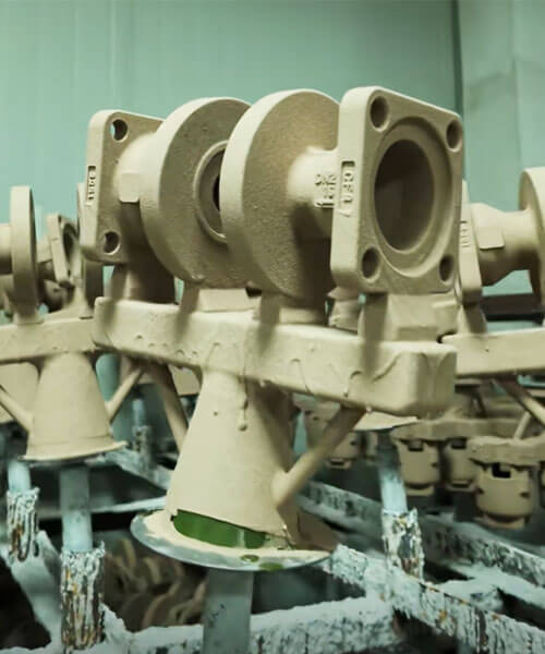
Investment casting commonly uses a tree structure to connect multiple wax patterns to a central sprue. The design must distribute molten metal consistently across all patterns.
An unbalanced gating tree may cause some cavities to fill earlier than others, while remote patterns may experience greater temperature loss or insufficient metal supply.
During evaluation, размислити:
- The distance between individual patterns and the central sprue.
- The number and position of ingates on each pattern.
- Differences in casting size and wall thickness.
- The filling sequence across the entire tree.
- The thermal condition of the ceramic shell.
- The ease of cutting off gates and finishing the castings.
A well-balanced tree improves filling consistency, reduces variation between castings, and supports more stable batch production.
Balance Feeding Performance and Gate Removal
У инвестиционом ливењу, ingates must provide sufficient metal flow while also allowing practical removal after solidification.
An excessively thin ingate may freeze too early and restrict feeding. An unnecessarily thick ingate can increase metal consumption and gate-removal work, and may leave a larger local finishing area.
The appropriate design should consider both casting quality and downstream operations, including cutting, млевење, ЦНЦ обрада, и дорада површине.
6. How to Optimize and Validate a Gating System
A reliable gating system should be developed through a combination of engineering calculations, симулација ливења, trial production, and defect analysis.
Корак 1: Analyze the Casting Geometry
Start with the casting itself, not the gating system. Review the 3D model, casting weight, расподела дебљине зида, Критичне димензије, Унутрашње одломаке, and potential hot spots.
Identify thin sections that may freeze prematurely, thick regions that require feeding, and areas vulnerable to direct metal impact.
Корак 2: Determine the Filling and Feeding Strategy
Select appropriate ingate locations and determine how molten metal should enter and move through the cavity.
The design should achieve complete filling without excessive turbulence and should preserve effective feeding paths to critical hot spots.
Корак 3: Calculate the Gating Dimensions
Estimate the required pouring time, total gating area, sprue dimensions, димензије тркача, and ingate cross-sections.
The calculations should account for alloy properties, casting volume, metallostatic head, услови калупа, и захтеви производње.
Корак 4: Evaluate the Flow and Solidification Behavior
For complex or high-value castings, casting simulation can help predict:
- Filling sequence and flow velocity.
- Potential air entrapment and oxide-film formation.
- Incomplete filling and cold-shut locations.
- Temperature distribution during filling.
- Hot spots and predicted shrinkage regions.
- Riser effectiveness and feeding-path continuity.
Simulation results should be interpreted by experienced casting engineers. A visually smooth filling animation does not automatically guarantee clean metal or defect-free castings.
Корак 5: Conduct Trial Casting and Inspect Results
After the initial design is established, conduct trial production under controlled pouring conditions.
Evaluate the castings using appropriate inspection methods, као што је:
- Visual inspection for surface erosion, flow marks, и непотпуно пуњење.
- Radiographic testing for internal porosity and inclusions.
- Penetrant testing for surface-breaking defects.
- Ultrasonic testing where material and geometry permit.
- Metallographic examination to identify shrinkage, инклузије, and microstructural abnormalities.
- Dimensional inspection to verify casting consistency.
The inspection method should match the defect type, материјал, геометрија ливења, and applicable customer requirements.
Корак 6: Refine the Design Based on Defect Distribution
Record the location, фреквенција, and severity of defects. If defects repeatedly occur in the same region, compare their distribution with the gating layout and solidification pattern.
На пример:
- Erosion near an ingate may indicate excessive local velocity or direct metal impact.
- Repeated inclusions along the flow path may indicate inadequate inclusion control or melt cleanliness.
- Misruns at remote thin sections may indicate insufficient filling capacity or excessive temperature loss.
- Shrinkage at thick sections may indicate inadequate feeding rather than insufficient total gating area.
Adjust one or more relevant variables and verify the result through another controlled trial.
This approach is more effective than changing several parameters simultaneously without identifying their individual effects.
7. Why Gating System Design Matters to Final Casting Quality
Gating system design directly influences the stability, доследност, and economic performance of casting production.
A well-designed system reduces unnecessary metal turbulence, improves inclusion control, supports gas evacuation, and maintains suitable filling and feeding conditions.
For precision investment castings, these requirements become even more important because complex geometries, танки зидови, and ceramic shell limitations leave less room for process variation.
Нехрђајући челик, карбонски челик, легура челика, and other engineering alloys also have different fluidity, понашање оксидације, and solidification characteristics.
Their gating systems should therefore be designed according to the specific alloy and casting geometry.
У Лангхе индустрија, gating system design is considered an integral part of the investment casting process rather than a separate tooling detail.
From initial 3D model evaluation and ingate positioning to mold filling analysis, trial casting, и преглед кварова, each stage is reviewed to achieve stable production and consistent casting quality.
Whether developing stainless steel valve bodies, Компоненте пумпе, industrial equipment parts, or other custom precision castings, an effective gating system helps reduce porosity, инклузије, мисунс, and unnecessary material waste.
Контактирајте Лангхе to discuss your custom investment casting requirements and develop a gating solution tailored to your part geometry, материјал, and production objectives.
8. Закључак
A good gating system produces castings with stable filling, reliable slag retention, smooth venting, секвенцијално очвршћавање, few defects, and high yield.
A bad gating system produces castings that are washed, blocked, спор, or chaotic—with porosity, slag holes, хладноће, скупљање, and erosion defects appearing in batches.
The gating system is not a peripheral detail. It is the first process decision that determines whether the mold can be filled properly and whether the casting can solidify soundly.
Judge the system before you pour. If the system fails the criteria, fix the system—not the pouring temperature, not the sand, not the operator.
In my experience, the foundries that control gating design produce consistent quality. The ones that treat gating as a “hook it up and pour” step spend their days chasing defects. The difference is not luck. It is design discipline.
Често постављана питања
What are the four main components of a casting gating system?
Pouring basin, спруе, тркач, и ингате.
What are the four core tasks of gating design?
Stable flow, slag retention, одзрачивање, and sequential filling.
What happens if the ingate solidifies too early?
It cuts off the feeding path from the riser to the casting’s heavy sections, causing shrinkage porosity.
How do I know if the gating system is causing turbulence?
Look for wash marks, таласи, metal fins, адхезија песка, shell spalling, or broken edges on the casting.
К7: What is the mnemonic for gating evaluation?
Flow steady, distribute even, hold slag, vent out, cool fast, feed last.
Can I fix a bad gating system by increasing pouring temperature?
Не. Higher temperature may help filling temporarily, but it does not fix turbulence, slag retention, одзрачивање, or feeding problems. Fix the gating design.

