

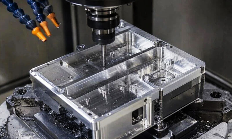
Over my 32 years running precision aluminum machining lines for automotive components, EV parts, нову енергију, and 3C electronic structural parts,
I’ve lost count of how many new process engineers walked in thinking “aluminum is soft, how hard can it be?” and walked out two weeks later staring at a bin of scrapped parts covered in burrs, chatter marks, и димензионални дрифт.
The lightweight revolution has pushed aluminum into every corner of precision manufacturing — and for good reason.
It delivers exceptional strength-to-weight ratio, одлична топлотна и електрична проводљивост, and high formability. But “easy to form” does not equal “easy to machine.”
Aluminum has its own unique set of failure modes, most of which come down to one core truth: aluminum doesn’t chip the way steel does.
It deforms, it welds itself to tool edges, it springs back, and it expands and contracts dramatically with temperature.
This guide breaks down the fundamentals of aluminum machinability, the eight most persistent production challenges, defect root causes by operation type, and full-process optimization strategies proven on the shop floor.
This isn’t textbook theory — it’s what we learned one scrapped batch, one tooling redesign, and one process tuning at a time.
1. Aluminum Machinability Basics: Оцене, Легуре & Rating System
The machinability of aluminum depends almost entirely on alloy composition and temper condition.
The industry uses an A–E five-level rating system (A = best, E = poorest) based on chip formation, Квалитет површинске завршетке, and tool wear rate.
It serves as a baseline reference — real-world performance also depends on tool type, Брзина сечења, and coolant delivery.
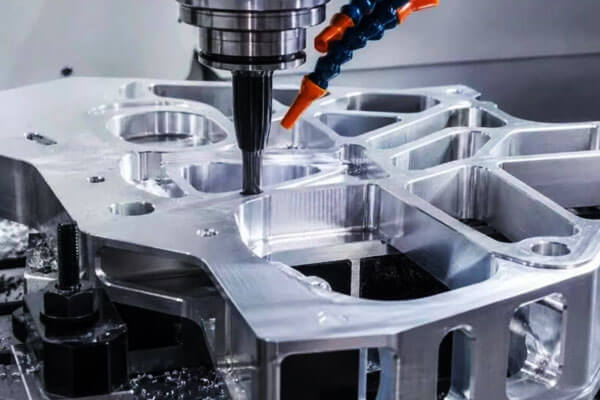
Wrought vs. Cast Aluminum Machinability
Wrought aluminum follows a clear pattern: higher strength and hardness = lower ductility = easier chip breaking = better machinability.
That is why T6, Т7, T8, and T9 tempers machine significantly better than soft O-temp material.
Cast aluminum does not follow the same linear relationship. Унутрашња порозност, large intermetallic phases, and silicon content all influence chip behavior.
У неким случајевима, softer cast grades machine better than hard ones because internal micro-defects help fracture chips cleanly.
Machinability Rating Table
| Wrought Alloy | Тврдоћа (500 кг оптерећење) | Machining Rating | Cast Alloy | Тврдоћа (500 кг оптерећење) | Machining Rating |
| 1100-О | 23 | Е | 238-Ф (Sand Cast) | 100 | Б |
| 2011-T8 | 100 | А | A240-F (Sand Cast) | 90 | А |
| 2219-Т851 | 130 | Б | 319-Т6 (Трајни калуп) | 95 | Б |
| 3003-Х18 | 55 | Д | 354-T61 (Трајни калуп) | 100 | Б |
| 5052-О | 47 | Д | 355-Т6 (Sand Cast) | 90 | Б |
| 5056-Х18 | 105 | Ц | 356-Т6 (Трајни калуп) | 90 | Б |
| 6061-О | 30 | Д | 357-Т6 (Sand Cast) | 90 | Б |
| 6061-Т6 | 95 | Ц | A380-F (Дие цаст) | 80 | Б |
| 6262-T9 | 120 | Б | 413-Ф (Дие цаст) | - | Б |
| 7075-О | 60 | Д | A535-F (Sand Cast) | - | Е |
| 7075-Т6 | 150 | Д | 713-Ф (Sand Cast) | 65 | Б |
Free-Machining Aluminum Alloys
Легуре попут 2011, 6262, и 6020 are formulated specifically for machinability. They contain intentional additions of lead, бизмут, or tin that form discrete second-phase particles.
These particles act as internal chip breakers, interrupting chip flow and preventing the long stringy chips that wrap around tools and damage surface finish.
Over the past 20 године, the industry has largely phased out leaded free-machining grades in favor of tin-based formulations for environmental compliance, but the core mechanism remains the same.
2. Тхе 8 Core Challenges of Aluminum Machining
Aluminum is generally considered easy to machine, but experienced machinists know that high cutting speed does not automatically mean stable precision machining.
The material is ductile, thermally responsive, and relatively compliant, while some alloys and cast conditions introduce their own tool-wear and chip-control problems.
After years on the shop floor, the same eight problems appear repeatedly.
They may look different from one part to another, but the underlying causes usually come back to tool geometry, топлота, материјално стање, држање посла, Резање параметара, and process sequence.
Уграђена ивица (Лук): The Most Common Tool-Related Problem
Уграђена ивица (Лук) occurs when aluminum adheres to the cutting edge under unfavorable combinations of cutting pressure, температура, геометрија алата, and lubrication.
Unlike conventional abrasive wear, this is primarily an adhesive wear mechanism.
Once aluminum begins accumulating on the edge, the effective tool geometry changes.
The cutting edge becomes less sharp, cutting forces become less stable, and the finished surface can deteriorate rapidly.
Typical consequences include poor surface finish, increased burrs, димензионални дрифт, and random scratching when the adhered aluminum breaks away.
Tool selection is therefore critical. Aluminum machining generally benefits from sharp, highly polished cutting edges and geometries designed for efficient chip flow.
Unnecessarily sticky tool coatings or dull edges can accelerate the problem. Proper lubrication and cutting conditions are equally important.
The practical warning sign is simple: when aluminum starts sticking to the tool, do not wait for the surface to fail before investigating the cause.
Machining Distortion: Термички, Residual-Stress, and Clamping Effects
Dimensional distortion is one of the hardest aluminum problems to control because several mechanisms can occur at the same time.
The first is Термално ширење. Many aluminum alloys have a coefficient of thermal expansion of roughly 23 × 10⁻⁶ / ° Ц, significantly higher than common steels.
А 1 m aluminum component can therefore change in length by approximately 0.023 mm for every 1°C temperature change.
The second is residual-stress release. Rolled plate, extruded sections, and forged blanks can contain internal stresses generated during material production.
Removing a large amount of material from one side can release these stresses and cause the component to bow, твист, or lose flatness.
The third is workholding deformation. Aluminum is comparatively compliant, so excessive fixture pressure can distort a thin wall or plate.
The part may return toward its original shape immediately after unclamping, leaving the machined dimensions inconsistent with the condition in which the part was measured.
A stable process therefore requires balanced material removal, appropriate workholding, and thermal control rather than simply increasing clamping force or taking heavier cuts.
Chatter and Vibration in Thin-Wall and Deep-Cavity Parts
Танки зидови, дубоки џепови, long tools, and slender components have limited structural stiffness.
When the cutting force exceeds the stability of the system, алат, радни комад, or both can vibrate.
The resulting chatter marks usually appear as repeating waves or lines on the machined surface.
Још важније, chatter changes the actual cutting path, making dimensional and geometric control much harder.
The solution usually starts with rigidity: shorten tool overhang, improve workholding, and support the workpiece where possible.
Cutting parameters then need to be adjusted to avoid unstable spindle-speed regions and excessive radial engagement.
For thin-wall aluminum parts, светло, controlled finishing passes are often more reliable than trying to remove the remaining stock in one aggressive pass.
Poor Surface Finish and Burr Formation
Aluminum’s ductility can make it difficult to produce clean edges and consistently smooth surfaces.
Poor cutting conditions can cause material to smear instead of shear cleanly, while long chips can recut against the finished surface.
The most common problem areas are hole exits, slot edges, оштар углови, and contour transitions.
Built-up edge makes the situation worse because fragments can break away from the tool and scratch the component.
For cosmetic or anodized parts, these defects become especially important. A surface that appears acceptable under ordinary shop lighting may show obvious machining lines, огреботине, or torn areas after finishing.
Good surface quality therefore begins with a sharp tool, stable cutting conditions, ефикасна евакуација чипова, and controlled edge preparation, rather than relying on post-machining polishing to hide the problem.
Dimensional Instability and Thermal Drift
Aluminum’s high thermal expansion means that temperature is effectively another machining variable.
На пример, a 10°C temperature change can correspond to approximately 0.23 mm of dimensional change per meter for a typical aluminum alloy. On a close-tolerance part, that is not a small error.
This becomes a particular problem when:
- A part is machined while warm and inspected after cooling
- Coolant temperature varies significantly
- Machine and workpiece temperatures change during a long production run
- Different batches are measured under different environmental conditions
For precision work, обрада, стабилизација, and inspection should be treated as one process.
Parts should be measured under controlled conditions, and the measurement reference temperature should be clearly defined.
Drilling and Tapping Difficulties
Drilling and tapping aluminum appear straightforward until chip evacuation becomes the limiting factor.
During drilling, poorly evacuated chips can rub against the hole wall and produce scratches, oversize holes, or taper.
The problem becomes more severe in deep holes because the chips have a longer path to travel.
Tapping presents a similar problem. Aluminum chips can adhere to the tap and fill the flutes, increasing cutting torque and potentially causing thread damage or tap breakage.
The practical solution is to match the tool geometry to the hole type, maintain adequate lubrication, and provide a reliable chip-evacuation path.
Through holes and blind holes often require different tap geometries, and deep-hole drilling may require controlled pecking or through-tool coolant.
Surface Defects Become More Visible After Anodizing
Anodizing is not a corrective process for poor machining. У многим случајевима, it makes existing surface differences easier to see.
Ознаке алата, огреботине, брбљање, уграђени чипови, small pits, and inconsistent surface preparation can become highly visible after anodizing, particularly on decorative or dyed aluminum components.
This creates a common production problem: the part passes dimensional inspection but fails the cosmetic inspection after surface treatment.
Да то избегне, the machining specification and anodizing specification should be developed together.
Critical visible surfaces need controlled machining, thorough cleaning, careful deburring, and appropriate protection before treatment.
Ношење алата: Adhesion Rather Than Simple Edge Chipping
Tool wear in aluminum does not always look like the classic flank wear seen in steel machining. A major problem is aluminum adhesion at the cutting edge.
The progression can be gradual:
Clean Edge → Aluminum Adhesion → Built-Up Edge → Changed Edge Geometry → Poor Surface Finish → Dimensional Drift
The tool may still appear physically intact, but its cutting geometry has already changed.
That is why waiting for obvious tool breakage is a poor tool-life strategy for precision aluminum machining.
Tool life should instead be monitored through a combination of surface-finish trends, димензионални дрифт, формирање неравнина, spindle load, and direct tool inspection.
Once significant built-up edge has developed, simply continuing to use the tool or lightly dressing the edge may not restore the original cutting geometry.
3. Common Defects By Machining Operation
Defects look different depending on the operation. Knowing the signature tells you exactly where to look for the root cause.
Milling Operations
| Дефект | Изглед | Primary Root Cause |
| Uneven surface / part bowing | Flatness out of spec; part curves upward | Residual blank stress; uneven stock removal; insufficient cooling; uneven clamping |
| Side wall chatter marks | Wave-like ripples on vertical walls | Excessive tool overhang; feed/speed mismatch; low part rigidity; spindle speed at resonant frequency |
| Површинске огреботине / hazy appearance | Linear scuffs; dull cloudy surface finish | Уграђена ивица; insufficient coolant lubrication; chip recirculation; chipped tool edge |
| Heavy edge burrs; long deburring time | Thick continuous burrs along part edges | Too small tool rake angle; too low cutting speed; no tool retract on exit; unoptimized climb milling |
| Inconsistent batch dimensions | Dimensions drift from first part to last | Cutting temperature variation; progressive BUE wear; fixture thermal expansion; parts measured warm |
Бушење & Boring Operations
| Дефект | Изглед | Primary Root Cause |
| Tapered hole (wider at top) | Oversize entrance, undersize exit; scored hole wall | Plugged flute channels; chips rubbing against wall; insufficient cooling, material welding to drill lands |
| Exit burr / hole edge collapse | Rolled-over burr at hole exit; delamination on thin stock | Poor drill cutting edge condition; too high feed rate; no backup support under thin material; slow retract |
| Drifted deep hole / Лоша површинска завршница | Hole wanders off center; rough internal finish | Poor chip evacuation; insufficient drill rigidity; inadequate through-tool coolant pressure |
Tapping Operations
| Дефект | Изглед | Primary Root Cause |
| Torn threads / powdery aluminum residue | Груб, torn thread flanks; fine aluminum powder | Tap BUE; too small flute volume; poor coolant lubrication; undersized tap drill |
| Seized / broken tap | Tap locks in hole; shears off | Continuous tapping without chip clearing; too high spindle speed; flutes packed with chips |
Turning Operations
| Дефект | Изглед | Primary Root Cause |
| Лоша завршна обрада површине / spiral tool marks | Visible spiral pattern; high Ra values | Nose BUE; too small nose radius; incorrect feed rate |
| Slender shaft bending / taper error | Shaft bows; diameter taper along length | Thermal growth; excessive tailstock pressure; cutting heat concentration |
4. Full-Process Optimization: From Blank to Finished Part
Fixing aluminum machining problems isn’t about turning up the coolant or slowing the feed.
It’s about system-level control from blank incoming to final inspection. These are the nine control points we tune on every line.
Blank Pre-Treatment: Stop Distortion at the Source
Most distortion problems start before the first tool touches the part.
- Stress relief first: All wrought plate and forged blanks get stress relief before machining. Either natural aging for 72 сати, or low-temperature baking at 120–150°C for 2–4 hours.
This releases residual stress so it doesn’t come out mid-machining and warp the part. - Uniform stock allowance: Leave a minimum 0.8–1.5 mm machining allowance per side. Never take all the stock from one side — uneven stress release guarantees warping.
- Pre-inspect castings: Check cast blanks for porosity and sand inclusions with NDT before machining.
Nothing wastes time like machining a whole part only to find a subsurface void at final inspection.
Избор алата: The Real Fix for Built-Up Edge
Tool selection is 80% of the BUE battle.
- Tool material:
-
- High-volume precision finishing: Пцд (поликристални дијамант) алата.
They barely stick to aluminum at all, deliver the best surface finish, and last 10–20x longer than carbide. Worth the premium for high-volume runs. - Small/medium batch production: Fine-grain carbide with uncoated or dedicated aluminum coatings (Тицн, ДЛЦ, Диамонд-Лике Царбон).
Never use standard TiN coatings on aluminum — aluminum adheres to TiN and BUE forms almost instantly. - Low-cost light duty: Челични алати велике брзине, only for low-speed light finishing cuts.
- High-volume precision finishing: Пцд (поликристални дијамант) алата.
- Tool geometry:
-
- Open rake angles of 15–25° reduce cutting compression and suppress BUE formation.
- Large chip pockets and sharp cutting edges ensure smooth chip evacuation.
- For milling cutters, use unequal tooth pitch to avoid resonant chatter.
- Use 0.2–0.4 mm nose radius for finishing. Too large a nose causes chatter on thin walls.
- Usage rules: Change the tool at the first sign of BUE or dulling. Never stone a dull tool and keep using it for finishing. Minimize tool overhang to maximize rigidity and reduce chatter.
Резање параметара: The “High Speed, Light Cut” Rule
Aluminum machining works best fast and shallow.
- Глодање:
-
- Брзина сечења: 300–1500 m/min for carbide; 2000–5000 m/min for PCD.
- Feed per tooth: 0.05–0,2 мм. Light cuts, never heavy slow feeds.
- Дубина сечења: 0.5–2 mm per roughing pass; ≤0.3 mm for finishing. Lighter cuts = less heat = less distortion.
- Бушење: High spindle speed, low feed rate, and periodic retract cycles for chip breaking. For deep holes, use peck drilling cycles to clear chips.
- Тапкање: Low spindle speeds. Use spiral flute taps for chip evacuation. Use bottoming taps for through holes, spiral pointed taps for blind holes. Size the tap drill 0.05–0.1 mm over standard for better thread clearance.
Расхладна течност & Подмазивање: Make or Break for Surface Finish
Coolant does more than cool — it lubricates the tool-chip interface to prevent BUE.
- Use dedicated aluminum machining coolants with extreme pressure lubricity packages. Straight oil > emulsion for lubrication.
- Never use water-only cooling. Lack of lubrication guarantees severe BUE and torn surface finish.
- Висока количина, high-pressure flood delivery directed right at the cutting zone. For deep holes, through-tool internal coolant is mandatory.
- Мкл (minimum quantity lubrication) with oil mist works very well for high-speed PCD machining. It leaves minimal residue and is anodizing-friendly.
Workholding: Avoid Crushing and Vibration
- Moderate clamping force: Aluminum is soft. Too much pressure leaves indentations and distorts thin walls. Use vacuum chuck workholding for thin sheet parts.
- Full support: Add backup supports under thin walls and overhangs. Never machine hanging unsupported sections — chatter is guaranteed.
- Fixture material: Use phenolic, најлон, or aluminum soft jaws for fixtures. Hard steel jaws will mark and crush aluminum parts.
- Pre-warm fixtures for batch production: Let fixtures come to operating temperature before running tight tolerance batches. Fixture expansion is a hidden source of dimensional drift.
Process Sequence: Minimize Distortion Step by Step
Process order matters more than most people realize.
- Follow the sequence: Roughing → Stress relief (bake or soak) → Semi-finishing → Finishing. Never rough and finish in one go.
- For thin-wall parts, take multiple light passes rather than one full-depth cut.
- Mill outside profiles and cavities first, drill and tap last. Milling forces can stretch and distort hole positions if done early.
- Let the part cool to room temperature before finishing passes. Stop the machine, walk away for 20 минут, then come back and take the final cut. This single step eliminates most thermal dimensional error.
- Add radius transitions at inside corners. Sharp corners = heavy burrs and stress concentrations.
Deburring Control
Deburring can eat up 30% of total part cost if you let it.
- Use tools with chamfered cutting edges to break edges during machining. In-process deburring beats manual deburring every time.
- Use arc-in/arc-out tool paths for contour milling. Never just stop and retract straight off an edge — that leaves a heavy burr.
- For parts going to anodizing, never heavy sand deburring — it causes uneven color and surface staining. Prefer vibratory deburring or ultrasonic deburring for uniform surface quality.
Димензионална стабилност & Environment Control
- Hold shop temperature to 20±2°C for tight tolerance work.
- Let parts rest 2–4 hours after machining before final inspection. Let them fully cool and stabilize.
- Calibrate micrometers and calipers for temperature error. A warm measuring tool gives wrong readings.
Pre-Finish Preparation for Anodizing & Премаз
- Clean all coolant residue off parts after machining. Residue causes spotting and staining after anodizing.
- Eliminate deep tool scratches, gouge marks, and chatter before finishing. Anodizing will not hide them — it will make them more visible.
- Mask and protect threaded holes and precision bores before cleaning and coating to avoid corrosion and edge damage.
5. Quick Troubleshooting Reference Table
| Проблем | Most Likely Cause | First Fix to Try |
| Уграђена ивица / Лоша површинска завршница | Wrong tool coating; insufficient lubrication | Switch to DLC or uncoated carbide; increase coolant pressure |
| Part warps after machining | Residual blank stress; uneven stock removal | Add pre-machining stress relief bake; equalize stock per side |
| Side wall chatter marks | Resonance; excessive tool overhang | Change spindle speed; reduce tool stickout |
| Tapered drilled hole | Chip packing; poor cooling | Use peck drill cycle; increase through-tool coolant |
Torn tapped threads |
Poor chip evacuation; undersized drill | Use spiral flute tap; increase tap drill size 0.05 мм |
| Batch dimensional drift | Топлотно ширење; progressive BUE | Let parts cool before measuring; index tool wear |
| Heavy edge burrs | Small rake angle; straight tool retract | Increase rake angle; use arc exit tool paths |
| Anodizing surface defects | Pre-machining scratches; coolant residue | Improve surface finish; clean thoroughly before coating |
6. Закључак
Aluminum machining is not about brute force or the fastest machine. It’s about system-level control of friction, топлота, стрес, and chip behavior.
The shops that excel at aluminum don’t have fancier machines — they have better process discipline.
They control blank stress, they select the right tools (and avoid the wrong coatings), they run fast light cuts, they flood the cut zone with lubricant, and they let parts cool before measuring.
The biggest mistake new engineers make is treating aluminum like soft steel. It’s a different material with different failure modes.
Уграђена ивица, термичка дисторзија, брбљање, and burr formation are not minor nuisances — they are the defining challenges of the process.
Address them systematically from blank to finished part, and you’ll go from fighting scrap every run to hitting tolerances batch after batch.
После 32 године, I still see new shops learn this the hard way. But once you get the system right, aluminum is one of the most productive, доследан, and capable precision materials you can machine.

