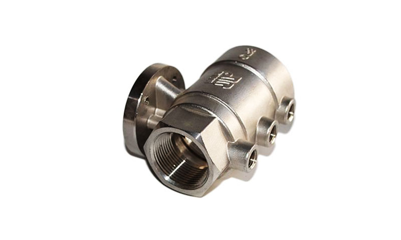
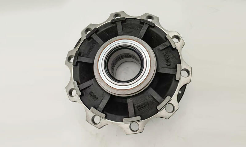
Pyörä- ja levyvalut edustavat suurta luokkaa pyöriviä rakenneosia, joita käytetään laajalti autojen jarrujärjestelmissä, mekaaniset voimansiirtolaitteet, kaivoskoneet ja merivoimalaitteet.
Tyypillisiä tuotteita ovat vauhtipyörät, jarrulevyt, hihnapyörät, pyöräkeskukset, vaihdelevyt ja jarrurummut.
Kaikilla näillä osilla on samat rakenteelliset ominaisuudet kuin akselisymmetrisillä pyörivillä kappaleilla: paksu keskusnapa, joka muodostaa näkyvät kuumat kohdat, siirtymäkohdat napojen ja ulkovanteiden välillä, ja ohutseinäiset ulkokehäreunat.
Äärimmäiset seinämän paksuuserot tuovat mukanaan metallurgisia haasteita, mukaan lukien napojen sisälle keskittynyt kutistumishuokoisuus, päätypinnan vääntymisen muodonmuutos, lämpöjännityshalkeamia, jäähtymistäipumus ohuissa osissa, epätasainen kehän kovuus, kuonasulkeumat ja kaasuhuokoset.
Prosessisuunnittelun ydinfilosofia on jähmettymisjaksojen säätely nousuputkien kautta, jäähdytys ja optimoidut porttiasettelut suunnatun jähmettymisen tai suhteellisen jähmettymisen toteuttamiseksi tarpeen mukaan.
Hiekkavalusta on tullut hallitseva valmistusreitti keskikokoisille ja suurille pyörille & levyvalut pienillä ja keskisuurilla tuotantomäärillä joustavan työkalun ansiosta, alhainen ennakkoinvestointi ja vahva sopeutumiskyky erilaisiin geometrioihin.
1. Pyörän ja levyn komponenttien rakenteelliset ominaisuudet ja valuhaasteet
Pyörän ja levyn valut ovat tyypillisiä pyörivät rakenneosat jolle on ominaista akselisymmetrinen geometria, suuria eroja osien paksuudessa, ja monimutkainen lämmönsiirtokäyttäytyminen jähmettymisen aikana.
Vaikka näillä komponenteilla on yleensä suhteellisen yksinkertainen ulkoinen muoto, niiden sisäinen valulaatu riippuu suuresti geometrian välisestä vuorovaikutuksesta, sulan metallin virtaus, ja jähmettymisen hallinta.
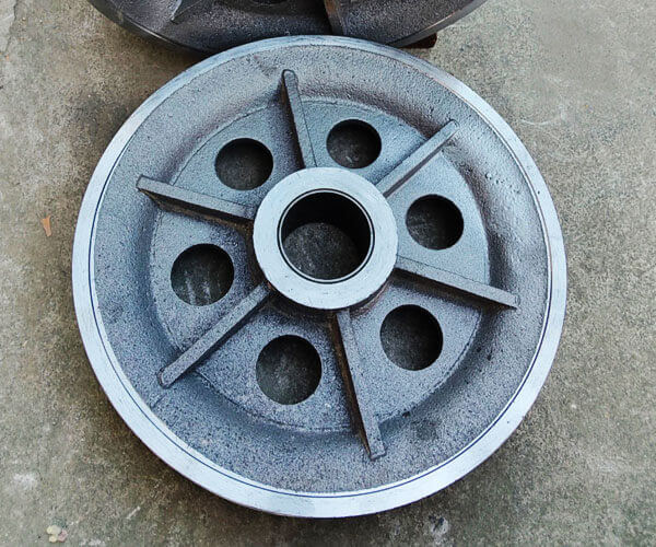
Pyörän ja levyn valujen tyypilliset rakenteelliset ominaisuudet
Pyörän tai kiekon valu voidaan yleensä jakaa kolmeen toiminta-alueeseen: keskitin, levy/verkko-osio, ja ulkoreuna.
Se keskuskeskitin on yleensä paksuin osa ja tarjoaa liitoskohdan akseleille, laakerit, pukut, tai siirtojärjestelmiin.
Suuren tilavuutensa ja hitaan jäähdytysnopeuden vuoksi, keskittimestä tulee tärkein lämpöpiste jähmettymisen aikana.
Nestemäinen metalli tällä alueella pysyy sulana pidempään kuin ympäröivät alueet, aiheuttaa suuren kutistumisvirheiden riskin, jos syöttöä ei tarjota riittävästi.
Se levy tai web-osio yhdistää navan ulkoreunaan ja on vastuussa mekaanisten kuormien siirtämisestä säilyttäen samalla kevyen rakenteen.
Tämä alue sisältää usein asteittaisia tai kaarevia paksuusmuutoksia. Virheellinen siirtymäsuunnittelu tai epätasainen jäähdytys voi aiheuttaa jäännösjännitystä, vääristymä, ja kuuma halkeilu.
Se ulkoreuna on tyypillisesti pienempi poikkileikkauspaksuus ja jäähtyy nopeammin kuin napa.
Tämän alueen liiallinen jäähdytys voi aiheuttaa ennenaikaista jähmettymistä ennen kuin napa on lopettanut syöttönsä, mikä johtaa sisäiseen huokoisuuteen ja epätasaisiin mekaanisiin ominaisuuksiin.
Näiden kolmen alueen välinen suhde määrää yleisen valukäyttäytymisen:
- Napa pysyy kuumana ja vaatii tehokasta syöttöä.
- Levy vaatii tasapainoisen jäähdytyksen muodonmuutosten estämiseksi.
- Vanne vaatii hallittua jähmettymistä ennenaikaisen jäätymisen välttämiseksi.
Siksi, onnistuneen valusuunnittelun on saavutettava hallittu lämpögradientti ulkoalueilta kohti keskisyöttövyöhykettä.
Pyörän ja levyn komponenttien suuret valuhaasteet
Pyörä- ja levyvalut sisältävät monimutkaista lämpökäyttäytymistä niiden tyypillisen rakenteen vuoksi paksut navat, ohuet verkkot, ja ulkovanteet.
Suuret erot leikkauspaksuuksissa luovat epätasaisen jähmettymisen, ruokintavaikeuksia, ja stressin keskittyminen.
Seuraavassa taulukossa on yhteenveto tärkeimmistä valuhaasteista ja vastaavista ohjausmenetelmistä.
| Casting Challenge | Syy ja mekanismi | Tyypilliset viat tai riskit | Suositeltavat valvontatoimenpiteet |
| Kutistumishuokoisuus navan lämpöpisteessä | Keskinapalla on suurin leikkauspaksuus ja pisin jähmettymisaika. Koska ympäröivät alueet jäätyvät aikaisemmin, syöttökanavat voivat tukkeutua, estää nestemäisen metallin kompensoinnin kiinteytyskutistumista varten. | Sisäiset kutistumisontelot, mikrohuokoisuus, vähentynyt väsymisvoima, huonot ultraäänitarkastustulokset. | Käytä suunnattua jähmettymismallia; optimoida nousuputken koko ja sijainti; käytä eristettyjä/eksotermisiä nousuputkia, ulkoiset vilunväristykset, ja oikea kaatolämpötilan säätö. |
| Epätasainen jäähdytys ja lämpöstressin muodostuminen | Ohut reuna- ja verkkoosat jäähtyvät nopeammin, kun paksu napa pysyy kuumana pidemmän aikaa. Erilaiset jäähdytysnopeudet aiheuttavat lämpögradientteja ja epätasaista supistumista. | Kuumia halkeamia, jäännöstressi, levyn vääntyminen, pyöreyden menetys, koneistusvääristymiä, dynaaminen epätasapaino. | Optimoi heittosuunta, muotin jäykkyys, jäähdytysolosuhteet, ja soveltaa jännitystä vähentävää lämpökäsittelyä tarkkuuskomponentteihin. |
Ohuiden levyjen ja verkko-osien epätäydellinen täyttö |
Ohuet osat menettävät lämpöä nopeasti muotin täytön aikana. Jos sulan metallin lämpötila laskee alle kriittisen täyttölämpötilan, ontelon täydellinen täyttäminen vaikeutuu. | Väärinkäytökset, kylmä sulkeutuu, epätäydelliset reunat, huono pinnanlaatu. | Optimoi portin sijainti, täyttönopeus, kaatamislämpötila, ja käytä tasaisia matalapyörteisiä täyttöjärjestelmiä, kuten renkaan muotoisia sivuportteja tai pohjatäyttöä. |
| Kaasun huokoisuus ja ei-metalliset sulkeumat | Myrskyinen sulan metallin virtaus aiheuttaa ilman mukana kulkeutumisen, hapetus, kuonan sekoitus, ja homeeroosiota. Suuret valumismäärät lisäävät inkluusioriskiä. | Puhallusreiät, pinnan huokoisuus, oksidiviat, kuonasulkeumat, heikentynyt väsymyskyky. | Käytä matalan turbulenssin porttijärjestelmiä, keraamiset vaahtosuodattimet, tehokas kuonanpoisto, oikea homeen läpäisevyys, ja vakaat kaatokäytännöt. |
| Mitat vääristymät ja koneistuksen epävakaus | Epätasainen supistuminen jäähtymisen aikana aiheuttaa sisäistä jännityksen kertymistä. Kuuma napa rajoittaa kylmempien vanneosien kutistumista. | Tasaisuuden poikkeama, samankeskisyyden menetys, out-of-round olosuhteet, liiallinen koneistusvara. | Paranna jäähdytyssymmetriaa, optimoida muotin suunnittelu, ohjaa shakeout-aikaa, ja suorittaa stressiä lievittävää hoitoa tarvittaessa. |
2. Kokonaisprosessin asettelu & Erosuunnitelmat
Prosessin asettelu hiekkavalu pyörän ja levyn osat ovat kriittinen tekijä, joka määrää täyttökäyttäytymisen, jähmettymissekvenssi, mitat tarkkuus, ja lopullinen casting -laatu.
Toisin kuin yksinkertaisen muotoiset valukappaleet, pyörän komponentit sisältävät merkittäviä eroja poikkileikkauksen paksuudessa keskuskeskitin, levy/verkko, ja ulkoreuna, mikä tekee valusuunnan ja jakotavan valinta erityisen tärkeäksi.
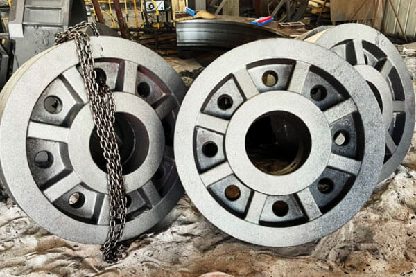
Horisontaalinen erotusprosessi (Yleisin ratkaisu)
Vaakaleikkaus on yleisimmin käytetty menetelmä pyörän ja kiekkojen valussa, varsinkin lentopyörät, jarrulevyt, hihnapyörät, pienet ja keskisuuret keskittimet, ja yleiset teollisuuslevyt.
Tässä järjestelyssä, valu on asetettu vaakasuoraan, ja jakotaso valitaan yleensä levy- tai rainaosan kautta.
Muotti on jaettu ylempään kahvaan ja alavastukseen, mahdollistaa kätevän kuvion poistamisen, ydinasennus, ja muotin kokoonpano.
Tämä menetelmä on laajalti yhteensopiva molempien kanssa:
- Vihreä hiekkavalujärjestelmät massatuotantoon;
- Hartsisidotut hiekkaprosessit keskisuurten ja pienten erien tuotantoon.
Vaakasuoran erotuksen tärkeimmät edut ovat sen yksinkertainen prosessiasettelu, pieni työkaluinvestointi, ja erinomainen tuotantotehokkuus.
Ytimen sijoitus on suhteellisen yksinkertaista, joten se sopii komponenteille, joissa on keskellä reikiä, sisäiset ontelot, tai akselin kiinnitysrakenteita.
Tyypillisiä porttijärjestelyjä ovat mm:
- Keski yläportti, jossa sula metalli tulee napa-alueen läpi ja virtaa ulospäin vannetta kohti;
- Kehämäinen sivuportti, jossa sulaa metallia pääsee tasaisesti kehän ympärille täytön vakauden parantamiseksi.
Kuitenkin, vaakasuuntaisella muovauksella on myös tiettyjä rajoituksia. Koska valun ylä- ja alapinnat kokevat erilaiset lämmönsiirtoolosuhteet, jäähdytys on usein epäsymmetristä.
Tämä voi johtaa siihen:
- Epätasainen kutistuminen;
- Päätypinnan vääntyminen;
- Jäljellä oleva stressi;
- Mittapoikkeama.
Lisäksi, muotin ontelon yläpinnalla on suurempi taipumus vangita kaasua ja ei-metallisia sulkeumia, mikä saattaa aiheuttaa:
- Puhallusreiät;
- Kuonan sulkeumia;
- Pintavirheet.
Siksi, tarkkuuskriittisille pyöräkomponenteille, Vaakasuora erottelu vaatii usein lisätoimenpiteitä, kuten parannetun tuuletuksen, optimoitu portti, ja ohjattu jäähdytys.
Pystysuuntainen erotus ja pystysuora kaatoprosessi
Pystyleikkausprosessi asettaa pyörän tai kiekon valun pystysuoraan, muotti halkeaa komponentin säteen suunnassa.
Tätä menetelmää käytetään pääasiassa korkean tarkkuuden pyörän navat, raskaat vetopyörät, rautatiekomponentit, ja suuret pyörivät osat, jotka vaativat erinomaista mittavakautta.
Verrattuna vaakasuuntaiseen valuun, pystysuora valu tarjoaa symmetrisemmän lämpöympäristön.
Valun koko ympärysmitta kokee tasaisemman jäähdytysnopeuden, mikä vähentää merkittävästi lämpötilaeroja eri alueiden välillä.
Suurimpia etuja ovat mm:
- Parempi pyöreys ja samankeskisyys;
- Vähentynyt muodonmuutos jäähdytyksen jälkeen;
- Tasapainoisempi mikrorakenteen jakautuminen;
- Pienempi jäännösjännitys.
Koska valu on sijoitettu pystysuoraan, myös sulan metallin virtausta voidaan hallita paremmin, vähentää epätasaisen täytön riskiä ylä- ja alaosien välillä.
Kuitenkin, pystyjako vaatii kehittyneempää muovauskykyä. Suurimpia haasteita ovat mm:
- Monimutkaisempi kuvio ja ydin;
- Korkeammat muotin kokoonpanovaatimukset;
- Lisääntynyt vaikeus suurten muottien käsittelyssä;
- Suuremmat vaatimukset nosto- ja asemointilaitteille.
Siksi, Tätä menetelmää käytetään yleisesti hartsihiekan tuotantoympäristöt, erityisesti keskimääräisille tai räätälöityille raskaille valukappaleille suuren volyymin automatisoidun tuotannon sijaan.
Kalteva kaatoprosessi (Hybridioptimointimenetelmä)
Kalteva valu on parannettu prosessi, joka perustuu vaakasuuntaisiin muovausperiaatteisiin.
Kaatamisen aikana, muotti on kallistettu säädetyssä kulmassa, tyypillisesti ympäri 10°–25°, mahdollistaen sulan metallin pääsyn onteloon vakaammissa olosuhteissa.
Tämä menetelmä yhdistää vaaka- ja pystysuoran valun edut parantamalla molempia:
- Täytön sileys;
- Kiinteytyssuunnan ohjaus.
Kalteva asento vähentää suoraa metallin iskua muotin pintaan ja vähentää turbulenssia täytön aikana.
Samaan aikaan, se edistää edullisempaa lämpögradienttia, auttaa sulaa metallia syöttämään napa-aluetta kohti.
Kalteva kaato sopii erityisen hyvin:
- Pallorautaiset pyörät;
- Isot levyvalut;
- Komponentit, joilla on voimakas navan kutistumistaipumus.
Sen tärkeimpiä etuja ovat mm:
- Vähentynyt oksidin inkluusiomuodostus;
- Parannettu navan syöttöteho;
- Pienempi kutistumishuokoisuuden riski;
- Parempi mittojen vakaus.
Kuitenkin, kalteva kaato vaatii lisälaitteita tai kiinnikkeitä muotin kulman säätämiseksi tarkasti, mikä tekee siitä sopivamman erikoistuotantoon tavallisten muovauslinjojen sijaan.
3. Hiekkamuotin suunnittelu- ja valmistusprosessi
Hiekkamuotien laatu määrää suoraan täyttökäyttäytymisen, pinnan laatu, mitat tarkkuus, ja pyörän ja levyn valujen sisäinen virheetön.
Koska nämä komponentit tyypillisesti yhdistyvät suuret halkaisijat, paksut navat, ohuita verkkoosia, ja monimutkaiset lämmönsiirtoolosuhteet, muovausprosessin on tarjottava riittävä lujuus onkalon stabiilisuuden ylläpitämiseksi, samalla kun säilytetään hyvä läpäisevyys ja kokoontaittuvuus.
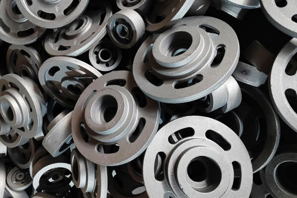
Vihreä hiekkamuovaus pienten ja keskikokoisten pyöräkomponenttien massatuotantoon
Vihreä hiekkamuovaus on yksi yleisimmin käytetyistä ja taloudellisimmista menetelmistä pienten ja keskikokoisten pyörä- ja levyvalujen valmistuksessa, kuten:
- Hihnapyörät;
- Pienet vauhtipyörät;
- Jarrurummut;
- Yleiset teollisuuslevyt.
Tässä prosessissa käytetään piidioksidihiekan seosta, bentoniitti savi, vettä, ja hiililisäaineita uudelleenkäytettävän muovausmateriaalin luomiseksi.
Se soveltuu erityisesti automatisoituihin tuotantolinjoihin, joissa vaaditaan korkeaa tuottavuutta ja alhaisia valmistuskustannuksia.
Vihreän hiekan suorituskyky riippuu voimakkaasti sen fysikaalisista ominaisuuksista. Tyypillisiä ohjausparametreja ovat mm:
| Parametri | Tyypillinen alue | Vaikutus suoratoiston laatuun |
| Kosteuspitoisuus | 3.2%–3,8 % | Säätelee muotin lujuutta, plastisuus, ja kaasuntuotanto |
| Tiivistettävyys | 38%–45% | Määrittää muottitiheyden ja ontelon stabiilisuuden |
| Läpäisevyys | ≥ 80 | Varmistaa tehokkaan kaasun poistumisen kaatamisen aikana |
| Vihreä puristuslujuus | 0.12-0,16 MPa | Tarjoaa riittävän muottilujuuden metallipainetta vastaan |
Aktiivisen bentoniitin ja hiililisäaineiden osuutta on valvottava huolellisesti. Bentoniitti tarjoaa sidoslujuuden, kun taas hiilipöly tai vastaavat hiilipitoiset lisäaineet auttavat vähentämään:
- Metallin tunkeutuminen;
- Palavia vikoja;
- Pinnan karheus;
- Kaasuun liittyvät pintavirheet.
Tuotannon aikana, Myös talteenotetun hiekan lämpötilaa on valvottava. Kuuma regeneroitu hiekka voi vaikuttaa negatiivisesti kosteuden jakautumiseen ja heikentää muotin laatua, mikä johtaa huonoon pintakäsittelyyn ja mittojen epävakauteen.
Pyörien ja kiekkojen valuihin, Lisäilmanpoistotoimenpiteitä käytetään yleensä, koska kaasulla on taipumus kerääntyä navan ja rainan osien korkeimpien kohtien ympärille.
Tyypillisiä ratkaisuja ovat mm:
- Rengasmaiset tuuletusurat jakopinnassa;
- Kaasunpoistoreiät muotin korkeissa kohdissa;
- Ylimääräiset tuuletusputket suljettujen onteloiden yläpuolella.
Kuitenkin, Vihreällä hiekkamuovauksella on myös rajoituksia. Koska muotilla on suhteellisen alhainen jäykkyys ja kohtalainen mittastabiilius, tyypillinen mittatarkkuus on noin CT9 - CT11 valutoleranssistandardien mukaisesti.
Lisäksi, vihreiden hiekkamuottien suhteellisen hitaat ja hallitsemattomat jäähdytysominaisuudet lisäävät kutistumisvirheiden riskiä paksuissa napaosissa.
Siksi, vihreää hiekkaa ei yleensä suositella raskaaseen pallografiittiraudan pyörännapoihin, jotka vaativat tiukkaa ultraäänitarkastusta tai korkeaa väsymiskykyä.
Itsekovettuva hartsihiekkamuovaus suuriin ja tehokkaisiin pyörän valuihin
Isoille pyörännapoille, raskaat vauhtipyörät, rautatiekomponentit, ja valukappaleet, jotka edellyttävät tiukkaa ainetta rikkomatonta testausta, itsestään kovettuva hartsihiekka on suositeltu muovaustekniikka.
Toisin kuin vihreä hiekka, hartsihiekka saavuttaa muottilujuuden hartsin ja kovettimen välisen kemiallisen sidoksen kautta, mahdollistaa suurten ja monimutkaisten muottien tuotannon ilman ulkoista tiivistyslaitteistoa.
Tyypillisiä materiaaleja ovat mm:
- 70/140 verkko silikahiekkaa;
- Keramsiittihiekka parantaa lämmönkestävyyttä;
- Furaanihartsi tai alkaliset fenolihartsijärjestelmät.
Hartsin lisäyssuhdetta säädetään yleensä noin 1.0%–1,4 %, samalla kun kovettimen annostusta säädetään:
- Ympäristön lämpötila;
- Kosteus;
- Vaadittu kovettumisnopeus;
- Tuotantosyklin vaatimukset.
Hartsihiekalla on useita tärkeitä etuja pyörän ja kiekkojen valuissa:
Parannettu mittatarkkuus
Hartsihiekkamuotien korkea jäykkyys ja stabiilisuus mahdollistavat likimääräisen mittatarkkuuden CT8-CT9, joka on huomattavasti parempi kuin perinteinen vihreä hiekkamuovaus.
Tämä on erityisen tärkeää pyöriville osille, joissa mittapoikkeamat voivat vaikuttaa:
- Tasapainoinen suorituskyky;
- Akselin kohdistus;
- Työstölisä;
- Käyttöikä.
Parempi kyky monimutkaisille ytimille
Suuret pyörävalut vaativat usein sisäisiä onteloita, asennusreiät, tai monimutkaisia naparakenteita. Hartsihiekka mahdollistaa tuotannon:
- Suuret ydinkokoonpanot;
- Ohuet ja monimutkaiset hiekkaytimet;
- Tarkat sisäiset kohdat.
Tämä tekee siitä erittäin sopivan räätälöityyn, yksiosainen, ja pienerätuotanto.
Korkeampi pintalaatu
Tasaisempi muotinontelon pinta pienenee:
- Hiekan tarttuvuus;
- Pinnan karheus;
- Siivoustyömäärä;
- Työstölisä.
Kuitenkin, hartsihiekka tuo myös tiettyjä haasteita.
Koska hartsisideaineet tuottavat enemmän kaasua kaatamisen aikana, väärä prosessinohjaus voi aiheuttaa:
- Maanalaiset puhallusreiät;
- Kaasuhuokoisuus;
- Hiileen liittyviä vikoja.
Lisäksi, hartsihiekkamuotilla on korkeampi jäykkyys ja heikompi kokoon taittuvuus verrattuna vihreään hiekkaan. Paksuprofiilivaluihin, rajoitettu supistuminen voi lisätä riskiä:
- Lämpöjännitys;
- Kuuma halkeilu;
- Jäännösstressin keskittyminen.
Siksi, hartsihiekkaprosessit vaativat huolellista koordinointia muotin lujuuden välillä, nousevan suunnittelu, ja jäähdytyksen ohjaus.
Muotin pinnoitustekniikka
Muottipinnoitteella on keskeinen rooli pinnan laadun parantamisessa ja valuvirheiden ehkäisyssä, erityisesti pyörä- ja levykomponenteille, joissa on suuret kuumat osat ja monimutkaiset siirtymät.
Pinnoitteiden ensisijainen tarkoitus on luoda suojaava este sulan metallin ja hiekkamuotin välille, vähentää:
- Hiekan tunkeutuminen;
- Metalli-muottireaktio;
- Palavia vikoja;
- Pinnan karheus.
Eri materiaalit vaativat erilaisia pinnoitusjärjestelmiä.
Puolesta harmaa valurautapyörän valukappaleet, grafiittipohjaisia pinnoitteita käytetään yleisesti, koska grafiitti tarjoaa:
- Hyvä lämmönkestävyys;
- Vähentynyt metallin tunkeutuminen;
- Paranneltu pintakäsittely.
Puolesta pallografiittivalurauta ja paksuprofiilivalut, alkoholipohjaiset zirkonijauhepinnoitteet ovat yleensä edullisia niiden vuoksi:
- Korkea tulenkestävyys;
- Erinomainen kestävyys sulan raudan eroosiota vastaan;
- Vahva suoja lämpökohdissa.
Tyypillinen menettely sisältää:
- Ensimmäinen pinnoite, joka peittää koko ontelon pinnan;
- Täydellinen kuivaus kosteuden poistamiseksi;
- Toinen pinnoite lisää suojaa;
- Lopputarkastus ennen muotin kokoamista.
Riittämätön kuivaus voi tuottaa lisää kaasua kaatamisen aikana, kun taas liiallinen pinnoitteen paksuus voi heikentää läpäisevyyttä ja vaikuttaa valun laatuun.
Tuuletusjärjestelmän suunnittelu pyörä- ja kiekkomuotteille
Kaasunhallinta on kriittinen osa pyörän ja kiekkojen valua, koska niiden pyörimisgeometria luo luonnollisesti kaasun kerääntymisalueita.
Oikein suunniteltu tuuletusjärjestelmä sisältää tyypillisesti:
| Tuuletusmitta | Tyypillinen muotoilu | Funktio |
| Jakopinnan tuuletusurat | Rengasmaiset urat suunnilleen 0.4 mm × 6 mm | Tarjoaa kaasun poistokanavat muotin rajapinnalla |
| Napan tuuletustangot | φ8–12 mm tuuletusreiät tai tangot navan yläosassa | Vapauttaa tiivistettyä kaasua paksuista osista |
| Ytimen tuuletusjärjestelmä | Tuuleta johdot tai huokoiset kanavat hiekkaytimien sisällä | Ohjaa sisäiset ydinkaasut muotin ulkopuolelle |
| Pakokaasujen nousuputket | Sijaitsee valun korkeissa kohdissa | Parantaa täytön vakautta ja estää kaasun juuttumisen |
Tehokkaan tuuletussuunnittelun on säilytettävä tasapaino: riittämätön tuuletus aiheuttaa kaasuvikoja, kun taas liiallinen tuuletus voi heikentää hometta tai lisätä metallin tunkeutumisriskiä.
4. Suojausjärjestelmän suunnittelu pyörien ja levyjen valuihin
Porttijärjestelmällä on ratkaiseva rooli sisäisen laadun määrittämisessä, ulottuvuusvakaus, ja pyörän ja levyn valujen mekaaninen suorituskyky.
Niiden tyypillisen pyörivän geometrian ansiosta – massiivisella navalla, suhteellisen ohuita web-osia, ja ohuempi ulkoreuna – täyttöprosessia on valvottava huolellisesti turbulenssin välttämiseksi, oksidien mukana kulkeutuminen, kylmä sulkeutuu, epätäydellinen täyttö, ja lämpötilan epätasainen jakautuminen.
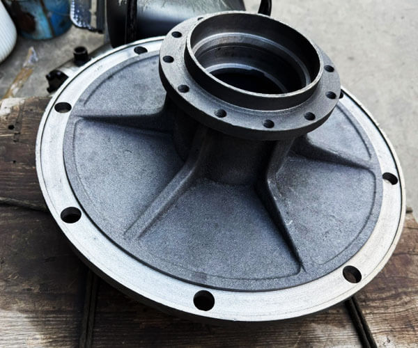
Keski yläporttijärjestelmä: Yksinkertainen asettelu vahvalla suunnatulla kiinteytymiskyvyllä
Keskiyläporttijärjestelmä on yksi perinteisistä ratkaisuista vauhtipyörille ja suhteellisen yksinkertaisille kiekon muotoisille valukappaleille.
Tässä mallissa, sula metalli tulee sisään keskinapa-alueelta ja virtaa säteittäisesti ulospäin reunaa kohti rainaosan läpi.
Tämä järjestely tarjoaa luonnollisen lämpötilagradientin, koska keskinapa pysyy kuumana kuin ulkoreuna täytön ja jähmettymisen aikana.
Yhdistettynä oikein suunniteltuihin nousuputkiin, järjestelmä voi edistää suunnattua jähmettymistä ohuemmista uloimmista osista napaa kohti, mahdollistaa keskipisteen ruokkimisen.
Kuitenkin, Keskeinen ruokintaasento aiheuttaa myös useita mahdollisia ongelmia.
Napa-alueen jatkuva altistuminen korkean lämpötilan sulalle metallille lisää navan lämpöpitoisuutta, mikä voi suurentaa kuumaa kohtaa ja lisätä kutistumisonteloiden tai mikrohuokoisuuden riskiä.
Lisäksi, metallivirran suora vaikutus keskelle voi aiheuttaa turbulenssia alkutäyttövaiheen aikana, lisäämällä oksidikalvon muodostumisen ja kuonan kulkeutumisen mahdollisuutta.
Suorituskyvyn parantamiseksi, nykyaikaisissa malleissa on usein keraamisia vaahtosuodattimia kaatoaltaassa, laajentaa useita säteittäisiä ulokkeita keskustasta, ja säädä virtaussuunta estääksesi suoran metallin iskun ohuisiin raina-alueisiin. Nämä muutokset auttavat vähentämään turbulenssia ja parantamaan sisäistä puhtautta.
Rengasrakoinen sivuporttijärjestelmä: Suositeltu ratkaisu jarrulevyille ja tarkkuuspyöriville osille
Jarrulevyille, jarrurummut, ja muut komponentit, jotka vaativat erinomaista mittatarkkuutta ja dynaamista tasapainoa, rengasmaista rakoa sivuporttia pidetään yleisesti yhtenä tehokkaimmista ratkaisuista.
Tässä kokoonpanossa, napa-alueen ympärille on järjestetty pyöreä juoksuohjain, useilla kapeilla ulokkeilla tasaisesti jaettuna kehälle.
Sula metalli tulee muotin onteloon samanaikaisesti useista suunnista, tuottaa tasapainoisen täyttökuvion.
Tämän järjestelmän suurin etu on sen kyky saavuttaa tasainen lämpötilan jakautuminen koko kehän ympäri.
Koska sula metalli saavuttaa valun eri alueet lähes samaan aikaan, lämpögradientit ovat minimoituja, vähentämällä jäännösjännitystä, vääristymä, ja pyöreyden poikkeama.
Suhteellisen hellävarainen täyttökäyttäytyminen vähentää myös turbulenssia verrattuna suoraan kaatoon. Pienempi turbulenssi tarkoittaa vähemmän hapettumista, vähemmän loukkuun jääneitä sulkeumia, ja pinnan laatu paranee.
Tämä tekee mallista erityisen sopivan jarrukomponenteille, joissa työstövara on rajoitettu ja mittojen vakaus on kriittinen.
Rengasmainen porttijärjestelmä tukee myös tasaisempaa jähmettymistä navan välillä, web, ja ulkoreuna.
Yhdistettynä oikein sijoitettujen nousuputkien ja jäähdytysten kanssa, se voi tehokkaasti hallita kutistumisvirheitä alueilla, joilla seinämän paksuus vaihtelee merkittävästi.
Pohja porttijärjestelmä: Laadukas täyttö raskaaseen käyttöön
Isoille ja raskaille pyörännapoille, vetopyörät, ja korkean kuormituksen teolliset komponentit, pohjaportti valitaan usein parhaan mahdollisen täyttölaadun saavuttamiseksi.
Pohjaporttijärjestelmässä, sula metalli tulee sisään muotin ontelon alaosasta ja nousee vähitellen ylöspäin.
Metallipinta pysyy suhteellisen vakaana täytön aikana, vähentää roiskeita merkittävästi, lentoliikenne, ja sekundaarinen hapetus.
Tämän menetelmän ensisijainen etu on sen erinomainen virtauksen säätö. Koska sula metalli nousee tasaisesti eikä putoa pystysuoraan, turbulenttisen virtauksen ja hiekan eroosion riski pienenee huomattavasti.
Tämä on erityisen tärkeää suurille valukappaleille, joissa pienetkin määrät oksidisulkeumia tai hiekkahiukkasia voivat vaikuttaa vakavasti väsymiskykyyn.
Kuitenkin, pohjatäytteellä on myös rajoituksia. Koska valun yläpinnat täytetään viimeisenä, niiden lämpötila saattaa laskea ennen kuin täydellinen ruokinta tapahtuu.
Siksi, pohjaportti on yhdistettävä huolellisesti tehokkaisiin nousuputkijärjestelmiin, eristävät hihat, ja ulkoiset jäähdytykset riittävän syöttöpaineen ylläpitämiseksi ja kutistumisen kompensoimiseksi paksuissa napaosissa.
Yleiset suunnitteluohjeet tehokkaille porttijärjestelmille
Riippumatta tietystä porttikonfiguraatiosta, Useita perusperiaatteita tulee noudattaa pyörien ja kiekkojen valusuunnittelussa.
Suljettu tai puolisuljettu porttijärjestelmä on yleensä edullinen, koska se vähentää turbulenssia ja parantaa kuonan erotusta.
Tyypillinen poikkileikkaussuhde putkien välillä, juoksija, ja ingate on noin:
Sprue : Juoksija : Entä = 1 : 1.2 : 0.8–1
Tämä suhde auttaa säilyttämään vakaan metallin nopeuden välttäen samalla liiallista turbulenssia.
Vaakasuorat kannattimet tulisi ulottaa viimeisen ulokkeen yli muodostamaan kuonankeräysvyöhykkeitä, jolloin epäpuhtaudet jäävät pois valuontelosta.
Keraamisia vaahtosuodattimia asennetaan usein jakojärjestelmään sulatteen puhtauden parantamiseksi.
Tärkeää on myös keulan muoto. Viuhkamainen, rako, tai tangentiaalisia holkkeja käytetään usein pyörän ja kiekkojen valuissa, koska ne jakavat sulan metallin vähitellen ja vähentävät suoraa vaikutusta muotin pintoihin.
Lopulta, Tehokkain porttisuunnittelu on sellainen, joka saavutetaan sileä täyte, ohjattu lämmön virtaus, ja progressiivinen jähmettyminen ohuista osista kohti syöttölähteitä.
Optimoimalla portin välistä suhdetta, nousut, vilunväristykset, ja valugeometria, valmistajat voivat vähentää merkittävästi kutistumishuokoisuutta, sulkeumat, muodonmuutos, ja muut yleiset viat vanteiden ja levyjen valuissa.
5. Ruokintajärjestelmän suunnittelu: Nousuja ja vilunväristyksiä
Syöttöjärjestelmä on kriittinen tekijä pyörän ja kiekkojen sisäisen laadun määrittämisessä.
Tyypillisen rakenteensa vuoksi - suuret navat, ohuempia verkkoja, ja ulkovanteet – näissä komponenteissa on merkittäviä eroja poikkileikkauksen paksuudessa.
Jähmettymisen aikana, paksu napa-alue pysyy nestemäisenä pidempään ja kokee suuremman tilavuuden kutistumisen, joten se on erittäin herkkä kutistuville onteloille ja mikrohuokoisuudelle.
Riser Design pyörän ja levyn valuihin
Keskiöalue on yleensä pääsyöttökohde, koska se edustaa valun suurinta lämpömassaa.
Nousuputket sijoitetaan yleensä navan yläpuolelle tai sen lähelle nestemäisen metallin aikaansaamiseksi jähmettymisen viimeisessä vaiheessa.
Puolesta harmaa valurautapyörän valukappaleet (FI-GJL-250, FI-GJL-300), suunnattua kiinteytymistä käytetään yleisesti.
Sylinterimäiset tai soikeat nousuputket sijoitetaan navan kuumille kohtille, ja niiden moduuli on suunniteltu korkeammaksi kuin syöttövyöhyke, jotta varmistetaan, että nousuputki jäätyy myöhemmin kuin valu.
Puolesta pallografiittivalurautapyörän valut (EN-GJS-450-10, EN-GJS-600-3), grafiitin laajeneminen eutektisen jähmettymisen aikana tarjoaa osittaisen itsesyötteen.
Siksi, liiallinen nousuputken tilavuus vältetään. Nykyaikaisissa malleissa yhdistetään tavallisesti pienemmät eristettyjä nousuputkia kylmyyteen, mikä parantaa valutuottoa ja säilyttää samalla sisäisen eheyden.
Raskaisiin pyörännapoihin, joissa on paksuja osia, eristettyjä nousuputkia tai eksotermisiä nousuputkia käytetään usein pidentämään syöttöaikaa ja vähentämään kutistumisvirheitä.
Jäähdytyksen ja jähmettymisen hallinta
Vilunväristyksiä käytetään nopeuttamaan paikallista jäähtymistä ja säätelemään jähmettymiskuviota.
Lisäämällä lämmönpoistoa valituilla alueilla, vilunväristykset vähentävät kuumien pisteiden kokoa ja edistävät suunnattua jähmettymistä kohti nousuputkea.
Pyörien ja kiekkojen valuihin, vilunväristykset ovat pääasiassa sijoitettu ympärille:
- Napan sivuseinät, joissa esiintyy lämpöpitoisuutta.
- Keskittimestä verkkoon siirtymäalueet.
- Paikalliset paksut osat, joilla on korkea kutistumisriski.
Kuitenkin, jäähdytyspaikka on optimoitava huolellisesti. Liiallinen jäähdytys ohuilla reuna-alueilla voi aiheuttaa ennenaikaista jähmettymistä, johtaa virheisiin, kylmä sulkeutuu, tai epätasainen kovuus.
Siksi, vilunväristyksiä vältetään yleensä ohuissa osissa, ellei erityistä mikrorakenteen hallintaa vaadita.
Tehokkain ruokintamuoto on yleensä yhdistelmä eristetyt nousuputket ja oikein sijoitetut jäähdytyslaitteet, jossa kylmät säätelevät lämpövirtausta, kun taas nousuputket tarjoavat lopullisen kutistumisen kompensoinnin.
Yleiset ruokintavirheet ja ratkaisut
Virheellinen syöttösuunnittelu voi johtaa useisiin tyypillisiin valuvirheisiin:
| Vika | Pääsyy | Optimointimenetelmä |
| Kutistumisontelo | Riittämätön nesteen syöttö keskuksen kuumissa paikoissa | Lisää nousuputken tehokkuutta tai paranna eristystä |
| Mikrohuokoisuus | Huono jähmettymissuunta ja syöttöpaine | Optimoi vilunväristykset ja lämpötilagradientti |
| Kuuma halkeilu | Liiallinen lämpöjännitys paksujen ja ohuiden osien välillä | Tasapainota jäähdytysnopeutta ja paranna ruokintaasettelua |
| Matala valusaanto | Ylisuuret nousuputket | Optimoi nousuputken koko prosessisimuloinnin avulla |
6. Sulaminen, Nodularisointi- ja inokulaatioprosessi pallografiittiraudasta valurautaa varten
Pallorautaa käytetään laajalti raskaiden pyörien ja kiekkojen valuissa, koska se tarjoaa erinomaisen lujuusyhdistelmän, sitkeys, väsymiskestävyys, ja kulumiskyky.
Harmaan valuraudaan verrattuna, pallografiittikyhmyjä, jotka vähentävät merkittävästi jännityspitoisuutta ja parantavat mekaanisia ominaisuuksia.
Kuitenkin, vakaan pallografiittiraudan laadun saavuttaminen edellyttää sulamisen tarkkaa hallintaa, magnesiumhoito, ja rokotusprosessit.
Sulamisprosessi ja kemiallinen valvonta
Sulamisprosessi luo perustan pallografiittiraudan laadulle.
Sähköisiä induktiouuneja käytetään yleisesti, koska ne tarjoavat tarkan lämpötilan ja kemiallisen koostumuksen hallinnan.
Tyypillisiä pallografiittivalurautalaatuja pyörän valuihin ovat mm:
- EN-GJS-450-10
- EN-GJS-600-3
Tyypillinen kemiallinen koostumusalue on:
| Elementti | Tyypillinen alue (%) | Funktio |
| Hiili (C) | 3.5–3.8 | Edistää grafiitin muodostumista |
| Pii (Ja) | 2.3–2.8 | Parantaa grafiitiota |
| Mangaani (Mn) | ≤0,4 | Vahvistaa matriisia |
| Rikki (S) | ≤0,025 | On valvottava ennen Mg-hoitoa |
| Fosfori (P) | ≤0,03 | Estää haurastumista |
| Magnesium (Mg) | 0.035-0,060 jäljellä | Muodostaa pallomaista grafiittia |
Tyypillinen lämpötilan säätö:
- Kosketuslämpötila: 1500-1550 °C
- Kaatamislämpötila: 1360-1420 °C
Rikin ja fosforin tiukka valvonta on välttämätöntä, koska liialliset tasot vähentävät nodulaarisuutta ja mekaanista suorituskykyä.
Magnesium-nodularisointihoito
Magnesiumkäsittely on avainvaihe, joka muuttaa grafiitin hiutaleista pallomaisiksi kyhmyiksi. Yleisin menetelmä käyttää sulaan rautaan lisättyä magnesium-ferrosii-seosta.
Hoidon aikana, magnesium reagoi rikin ja hapen kanssa, synnyttää voimakkaan reaktion.
Hoitolämpötilan oikea hallinta, seoksen lisäys, ja magnesiumin talteenotto on tarpeen stabiilin nodulaarisen grafiitin saamiseksi.
Huono nodularisaatio voi johtaa:
- Vermikulaarisen grafiitin muodostuminen.
- Vähentynyt vetolujuus ja venymä.
- Pienempi väsymiskestävyys.
Laadukas pallografiittirautarakenne pitäisi olla:
- Korkea grafiitin nodulaarisuus.
- Tasainen grafiitin jakautuminen.
- Hallittu kyhmyn koko.
- Sopiva ferriitti-/perliittinen matriisi suorituskykyvaatimusten mukaan.
Rokotus ja grafiitin jalostus
Inokulaatio parantaa grafiitin ydintymistä ja stabiloi lopullisen mikrorakenteen. Se suoritetaan yleensä kahdessa vaiheessa: ensimmäinen inokulaatio koputuksen aikana ja toissijainen inokulaatio kaatamisen aikana.
Kalsiumia sisältävät ferropiipohjaiset ymppäysaineet, barium, tai zirkoniumia käytetään yleisesti.
Tehokas rokotus auttaa:
- Lisää grafiittikyhmyjen määrää.
- Vähennä karbidin muodostumista.
- Paranna mekaanisia ominaisuuksia.
- Saavuta tasainen kovuusjakauma.
Suurille pyörän valuille, rokotus on erityisen tärkeää, koska hidas jäähtyminen hiekkamuoteissa voi johtaa karkeaan grafiittiin ja heikentyneeseen lujuuteen.
7. Ravistaa, Jäähdytys- ja lämpökäsittelyprosessi
Shakeout, jäähdytys, ja lämpökäsittelyvaiheilla on tärkeä rooli mittatarkkuuden ylläpitämisessä, mekaaniset ominaisuudet, ja pyörän ja kiekkojen valujen pitkäaikainen käyttövarmuus.
Vaikka valuprosessi on valmis jähmettymisen jälkeen, väärä käsittely jäähdytyksen aikana tai ennenaikainen poistaminen muotista voi aiheuttaa jäännösjännitystä, vääristymä, ja jopa halkeilee, erityisesti komponenteissa, joissa on suuri halkaisija, epätasainen seinämän paksuus, ja tiukat tasapainovaatimukset.
Shakeout ja Holding Time Control
Kaatamisen ja jähmettymisen jälkeen, valukappaleiden tulee olla hiekkamuotin sisällä riittävän kauan ennen ravistelua.
Hiekkamuoti tarjoaa lämmöneristyksen ja antaa valukappaleen jäähtyä vähitellen, vähentää lämpötilagradientteja paksujen ja ohuiden osien välillä.
Ennenaikainen ravistelu poistaa tämän lämpösuojan liian aikaisin, aiheuttaa epätasaista jäähdytystä ja lisää riskiä:
- Jäännöslämpöjännityksen aiheuttama navan muodonmuutos.
- Verkko vääristyy ja tasaisuuden menetys.
- Pintahalkeilu korkean jännityksen alueilla.
Tarvittava pitoaika riippuu pääasiassa valun koosta, seinämän paksuus, materiaalityyppi, ja muotin ominaisuudet.
Tyypilliset pitoajat ovat:
| Casting -tyyppi | Suositeltu pitoaika |
| Pienet pyörä- ja levyvalut | ≥ 30 minuutti |
| Keskikokoiset pyörännavat ja vauhtipyörät | 60-90 minuuttia |
| Suuret ja raskaat pyörävalut | 90-120 minuuttia tai kauemmin |
Suurille pallografiittirautapyörille, pidennetty jäähdytys muotin sisällä on usein suositeltavampaa, koska hidas jäähdytys auttaa vähentämään lämpögradientteja ja parantaa mittapysyvyyttä.
Shakeoutin jälkeen, valukappaleita tulee käsitellä varovasti. Suuria pyörien ja kiekkojen valukappaleita ei saa pinota tai asettaa epätasaisen tuen alle, koska niiden oma paino voi aiheuttaa pysyviä taivutusmuodonmuutoksia metallin ollessa vielä korotetussa lämpötilassa.
Hallittu jäähdytys Shakeoutin jälkeen
Muotista poistamisen jälkeen, pyörän ja levyn valujen tulee jatkaa jäähtymistä valvotuissa olosuhteissa.
Nopea jäähdytys, erityisesti suuriprofiilisille pallografiittirautakomponenteille, voi aiheuttaa liiallista lämpöjännitystä navan ja vanteen väliin.
Oikea jäähdytyskäytäntö sisältää:
- Vältä pakotettua jäähdytystä vedellä tai voimakkailla ilmavirroilla.
- Antaa valukappaleiden jäähtyä luonnollisesti valvotussa ympäristössä.
- Valukappaleiden tukeminen tasaisesti painovoiman vääristymisen estämiseksi.
Pallorautapyörille, hallittu jäähdytys vaikuttaa myös lopulliseen mikrorakenteeseen.
Hidas jäähdytys edistää grafiitin kasvua ja vähentää ei-toivottujen karbidien muodostumista, kun taas liialliset jäähdytysnopeudet voivat lisätä kovuutta ja vähentää sitkeyttä.
Stressiä lievittävä lämpökäsittely
Jäännösjännitystä syntyy valun aikana, koska eri osat supistuvat eri nopeudella jäähdytyksen aikana.
Paksu napa, ohut verkko, ja ulkoreuna kokevat erilaisen lämpösupistumiskäyttäytymisen, aiheuttaa sisäistä jännitystä, vaikka näkyviä vikoja ei olisikaan.
Erittäin tarkkoihin pyöräkomponentteihin, varsinkin jarrulevyt, vetopyörät, ja suuret navat, jännityksenpoistohehkutus suoritetaan yleensä ennen koneistusta.
Tyypillinen stressinpoistoprosessi sisältää:
- Lämmityslämpötila: 500-550 °C
- Odotusaika: määräytyy valun paksuuden ja painon mukaan
- Ohjattu uunin jäähdytys minimoi uuden lämpörasituksen
Tämä käsittely vähentää jäännösjännitystä ja parantaa koneistuksen vakautta. Ilman stressin lievitystä, valukappaleet voivat vääntyä karkea- tai viimeistelytyöstössä, koska materiaalin poisto vapauttaa sisäistä jännitystä.
8. Johtopäätös
Pyörän ja kiekon komponenttien hiekkavalu on pitkälle erikoistunut prosessi, joka vaatii huolellista koordinointia muottien suunnittelun välillä, porttitekniikka, ruokintastrategia, metallurgia, ja jäähdytyksen ohjaus.
Avain laadukkaiden pyörävalujen valmistukseen ei ole vain täydellinen täyttö, mutta ohjaa koko lämpö- ja nestevirtausprosessia:
- Oikean valusuunnan valitseminen;
- Vakaiden ja puhtaiden täyttöjärjestelmien suunnittelu;
- Keskittimen lämpöpisteiden hallinta;
- Tehokkaiden nousujen ja jäähdytysten käyttö;
- Pallorautametallurgian hallinta;
- Simulaatiopohjaisen optimoinnin käyttö.
Oikein suunnitelluilla hiekkavaluprosesseilla, valmistajat voivat valmistaa suuria ja monimutkaisia pyörä- ja levyvaluja, joilla on erinomaiset mekaaniset ominaisuudet, mitat tarkkuus, ja pitkäaikainen palveluvarmuus vaativiin teollisiin sovelluksiin.
LangHe – ammattimainen pyörä- ja levyvalujen valmistaja Kiinassa
LangHe on ammattilainen Kiinalainen valmistaja, joka on erikoistunut räätälöityihin vanteiden ja levyjen valuihin, korkealaatuisten valuratkaisujen tarjoaminen pyöriville teollisille komponenteille, vauhtipyörät mukaan lukien, jarrulevyt, pyöräkeskukset, hihnapyörät, vaihdelevyt, jarrurummut, ja raskaiden koneiden osia.
Pitkä kokemus hiekkavalu- ja hartsihiekkavalutekniikoista, LangHe tukee asiakkaita valusuunnittelusta ja prosessin optimoinnista tuotantoon, koneistus, tarkastus, ja lopullinen toimitus.
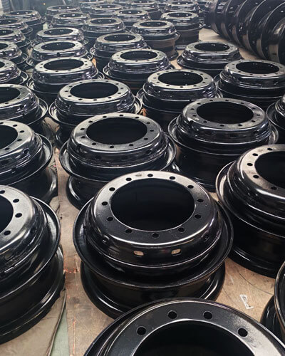
LangHe valmistaa pyörä- ja kiekkovaluja laajasta materiaalivalikoimasta, mukaan lukien harmaa valurauta, rauta- rauta, hiiliteräs, seosteräs, ja ruostumatonta terästä, täyttää autoteollisuuden vaatimukset, teollisuuslaitteet, energia, kuljetus, ja raskaiden koneiden sovelluksissa.
Tiukan laadunvalvonnan kautta, edistyneet valmistusominaisuudet, ja räätälöity tekninen tuki, LangHe toimittaa kestäviä, kustannustehokas, ja sovelluskohtaiset valuratkaisut asiakkaille ympäri maailmaa.
Luotettuna mukautetun pyörän ja levyn valuvalmistaja Kiinassa, LangHe on sitoutunut auttamaan globaaleja asiakkaita parantamaan tuotteiden luotettavuutta, optimoitu valutulos, ja alentaa valmistuskustannuksia ammattimaisen valuosaamisen ja jatkuvan prosessiinnovoinnin ansiosta.
Ota yhteyttä räätälöityjä tarkkuusvaluja varten.