In the manufacturing industry, understanding the full spectrum of machining methods is essential for process engineers, machinists, and production planners.
For years, newcomers to the field have struggled to distinguish between the various cutting processes—when to turn, when to mill, when to grind, and when to abandon traditional methods altogether in favour of electrical or laser-based processes.
This confusion is understandable. The machining landscape has expanded dramatically over the past century, evolving from simple manual lathe work to a sophisticated ecosystem of CNC machining centres, electrical discharge machines, laser cutters, and waterjet systems.
Each process has its own strengths, limitations, and ideal applications—and selecting the wrong one can lead to scrapped parts, damaged tools, and unnecessary costs.
This article systematically explains 13 common machining methods, including 8 traditional machining processes and 5 special machining technologies, helping engineers understand their principles, advantages, limitations, and typical applications.
1. The Three Fundamental Principles of Part Formation
Every mechanical component, from a simple washer to a complex turbine blade, is produced through one of three fundamental manufacturing principles.
These principles define how material is transformed from raw stock to finished part—and they serve as the primary distinction between different processing methods.
Principle 1: Material Formation (Δm ≈ 0)
In material formation processes, the overall mass of the workpiece remains almost unchanged before and after processing.
Instead of removing or adding material, the existing material is reshaped through plastic deformation, phase transformation, or solidification.
These processes are mainly used to manufacture the initial shapes of components, commonly referred to as blanks, preforms, or near-net-shape parts.
The formed parts may then undergo secondary machining operations to achieve precise dimensions and surface requirements.
Material formation processes are especially important because they determine the basic material structure, mechanical properties, and manufacturing efficiency of the final component.
| Process | Manufacturing Mechanism | Typical Applications | Key Advantages |
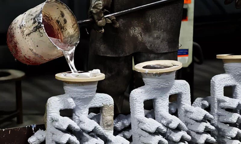
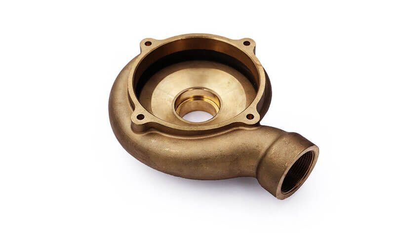
| Casting | Molten metal is poured into a mold cavity and solidifies into the desired shape. | Pump housings, valve bodies, engine blocks, machine bases, complex structural components. | Produces highly complex geometries, internal passages, and large components with relatively low material waste. |
| Forging | Heated metal is shaped through compressive forces using dies, presses, or hammers. | Shafts, gears, connecting rods, pressure components, aerospace structures. | Improves mechanical properties through refined grain flow, higher strength, and superior fatigue resistance. |
Powder Metallurgy |
Metal powders are compacted under pressure and sintered at elevated temperatures to form solid components. | Bearings, filters, gears, wear-resistant components, precision parts. | Extremely high material utilization, controlled porosity, and capability to produce special material compositions. |
Key Insight: While these processes are not “machining” in the traditional sense, they provide the starting material—the blank—that most precision components require.
Principle 2: Material Removal (Δm < 0)
Material removal, also known as subtractive manufacturing, is the core principle behind conventional machining.
In these processes, excess material is removed from an initial workpiece—such as a casting, forging, bar stock, or plate—to create the final geometry with precise dimensions, tolerances, and surface finishes.
This category includes the most widely used machining methods:
- Turning.
- Milling.
- Drilling.
- Boring.
- Grinding.
- Gear machining.
- Electrical discharge machining (EDM).
Material removal remains the dominant manufacturing approach for precision mechanical components because it provides excellent control over final part quality.
Core Characteristics:
- Material is removed, producing chips or swarf.
- Achieves the highest dimensional accuracy and surface finish.
- The most widely used method for producing precision components.
Key Insight
Material removal is the foundation of precision manufacturing because it converts near-net-shape blanks into functional engineering components.
A typical industrial manufacturing route often follows this pattern:
Casting / Forging → Rough Machining → Heat Treatment → Precision Machining → Surface Finishing
This combination balances material efficiency, mechanical performance, and dimensional accuracy.
Principle 3: Material Addition (Δm > 0)
Material addition processes create components by adding, depositing, or joining materials together.
Unlike subtractive manufacturing, which removes excess material, additive processes increase the amount of material during production.
This category includes both traditional joining technologies and modern additive manufacturing methods.
| Process | Manufacturing Mechanism | Typical Applications | Key Advantages |
| Welding | Materials are joined through heat, pressure, or a combination of both to create a permanent bond. | Structural frameworks, pipelines, pressure vessels, tanks, heavy equipment. | Produces strong permanent joints and enables large structures to be fabricated efficiently. |
| Brazing / Soldering | A filler metal is melted and distributed between components without melting the base materials. | Heat exchangers, electronic components, precision assemblies. | Allows joining of dissimilar materials with minimal thermal distortion. |
3D Printing (Additive Manufacturing) |
Material is deposited layer by layer according to a digital model. | Prototypes, lightweight structures, customized medical parts, complex geometries. | Provides exceptional design freedom and enables rapid production of complex shapes. |
Key Insight: Additive manufacturing is particularly valuable for prototyping, custom parts, and geometries that are impossible or extremely difficult to achieve through subtractive methods.
2. The 8 Traditional Machining Processes: The Backbone of Manufacturing
Traditional machining relies on mechanical cutting tools to remove material from a workpiece.
These processes are the workhorses of the manufacturing industry, capable of producing everything from simple shafts to complex moulds and dies. Here are the 8 most common traditional processes, their working principles, and their ideal applications.
Turning: The Process for Rotational Parts
Working Principle:
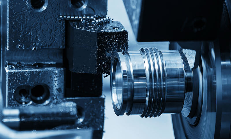
CNC Turning is a machining process in which the workpiece rotates (the primary motion) and a single-point cutting tool moves linearly (the feed motion).
The lathe is the machine tool used for turning operations. As the workpiece spins, the tool removes material to create cylindrical profiles, faces, tapers, threads, and other rotational features.

Why Turning Excels:
Turning offers exceptional precision for rotational parts because of the inherent stability of the process.
The rotating workpiece ensures that all features are concentric to the same axis, making it easy to achieve excellent coaxiality and perpendicularity between faces.
The cutting process is continuous (no interruptions), allowing for high cutting speeds, excellent surface finish, and long tool life.
| Parameter | Typical Range | Notes |
| Surface roughness | Ra 0.1 – 3.2 µm | Diamond turning of non-ferrous metals can achieve Ra <0.1 µm. |
| Dimensional accuracy | ±0.01 – 0.05 mm | Precision lathes can achieve ±0.005 mm. |
| Typical materials | Metals, plastics, composites | Not suitable for very hard materials (>HRC 60) without special tooling. |
Applications:
- Cylindrical parts: shafts, pins, rollers
- Disc-shaped parts: flanges, gears, flywheels
- Threaded components: bolts, screws, nuts
- Eccentric and non-round parts (on cam lathes)
Machine Types:
- Horizontal lathes: The most common type; handles a wide range of part sizes.
- Vertical lathes: Used for large, heavy disc-shaped components (e.g., brake drums, large gears).
- Swiss-type (automatic) lathes: Ideal for small, long, and complex parts (e.g., watch components, medical devices).
- CNC turning centres: Multi-axis machines capable of complex operations (turning, milling, drilling) in one setup.
Practical Tip: Turning is the process of choice for any part with a dominant rotational axis. For high-volume production, CNC lathes with bar feeders can run unattended for hours.
Milling: The Versatile All-Rounder
Working Principle:
CNC Milling uses a rotating multi-tooth cutter (the primary motion) to remove material from a stationary or moving workpiece.
The cutter axis is typically perpendicular to the workpiece surface (end milling) or parallel to it (peripheral milling).
Milling can produce flat surfaces, slots, pockets, contours, and complex 3D shapes.

Why Milling Excels:
Milling is the most versatile machining process. With the right cutter and setup, it can machine almost any feature on a workpiece: flat surfaces, grooves, profiles, cavities, and even complex 3D surfaces.
The intermittent cutting action, while generating some vibration, allows for high metal removal rates.
Key Distinction: Up Milling vs. Down Milling:
| Milling Type | Cutting Action | Best For | Tool Life |
| Up Milling (Conventional) | Chip thickness increases from zero to maximum. | Older machines with backlash; castings and forgings with hard skin. | Shorter (due to rubbing at entry). |
| Down Milling (Climb) | Chip thickness decreases from maximum to zero. | CNC machines with backlash compensation; better surface finish. | Longer (cleaner entry; less rubbing). |
Cutting Methods:
- End milling: Cutter axis perpendicular to the workpiece; used for slots, pockets, and profiles.
- Peripheral milling: Cutter axis parallel to the workpiece; used for flat surfaces.
- Face milling: Flat-faced cutter with inserts; used for large flat surfaces.
- Fly cutting: Single-point tool for large flat surfaces; low production rate but good finish.
Applications:
- Flat surfaces: top faces, mounting pads
- Slots and grooves: T-slots, keyways, dovetails
- Complex profiles: gears, cams, impellers
- 3D contours: mould cavities, die surfaces, aerospace components
- Thread milling: high-quality threads in hard materials
Tolerances and Surface Finish:
| Parameter | Typical Range |
| Surface roughness | Ra 0.8 – 6.3 µm |
| Dimensional accuracy | ±0.02 – 0.10 mm |
| Precision milling | ±0.005 – 0.01 mm (with high-end equipment) |
Practical Tip: When milling, always consider the rigidity of the setup. Long, slender cutters will deflect, leading to poor surface finish and inaccuracy. Use short, rigid tooling where possible.
Planing: The Low-Cost Flat Surface Solution
Working Principle:
Planing is a machining process in which a single-point cutting tool moves in a straight line (the primary motion), cutting across a workpiece that is held on a reciprocating table.
The workpiece moves past the stationary tool, which removes a layer of material on each pass. The tool returns to the start without cutting (idle stroke).
Why Planing Excels:
Planing is a low-cost solution for machining large, flat surfaces, especially for single parts or small batches.
The machines are relatively simple and inexpensive, and the tooling is basic (HSS tools).
The long, straight strokes are ideal for machining straight surfaces such as machine beds, guideways, and large base plates.
| Parameter | Typical Range | Notes |
| Surface roughness | Ra 1.6 – 6.3 µm | Good but rougher than milling. |
| Dimensional accuracy | ±0.05 – 0.20 mm | Less precise than milling. |
| Production rate | Low | The idle stroke wastes time. |
Applications:
- Large, flat surfaces: machine bases, beds, and tables
- Straight grooves: V-grooves, dovetails, keyways
- Single parts and small-batch jobs: repair and maintenance work
- Toolroom and die-making applications
Limitations:
- Low productivity: the idle stroke limits production rates.
- Low precision: not as accurate as milling.
- Limited shapes: can only produce flat or straight-line features.
Practical Tip: Planing is best suited for jobs where the cost of a milling machine or setup is prohibitive. It is rarely used in high-volume production.
Drilling: The Foundation of Hole Making
Working Principle:
Drilling is the process of creating a round hole in a workpiece using a rotating multi-point cutting tool called a drill (or twist drill).
The drill rotates (primary motion) and is fed into the workpiece (feed motion). The cutting edges at the tip remove material, while the flutes evacuate chips.
Why Drilling Excels:
Drilling is the simplest and most economical way to create holes in metal.
It can be performed on a wide range of machine tools: drill presses, milling machines, and even hand drills. Drilling is typically the first step in a sequence of hole-making operations.
| Parameter | Typical Range | Notes |
| Hole size range | 0.1 – 100+ mm | Small holes require special micro-drills. |
| Hole depth | Up to 10× diameter (standard) | Deep holes require specialised tooling (gun drilling). |
| Dimensional accuracy | ±0.05 – 0.2 mm | Drilling is a roughing operation; holes may be oversized. |
| Surface finish | Ra 3.2 – 12.5 µm | Relatively poor compared to reaming. |
Common Drilling-Related Operations:
| Operation | Description | Purpose |
| Reaming | Enlarges and finishes an existing hole to a precise diameter. | Precision hole sizing; improved roundness and surface finish. |
| Counterboring | Enlarges the top portion of a hole to a larger diameter. | Creates a shoulder for a screw head (socket-head cap screw). |
| Countersinking | Creates a conical taper at the top of a hole. | For flat-head screws and deburring. |
| Tapping | Cuts internal threads in a hole. | For threaded fasteners. |
Common Drilling Problems:
| Problem | Cause | Solution |
| Oversized hole | Drill wobble; worn drill; improper feed. | Use a centre drill; check drill alignment; reduce feed. |
| Hole location error | Workpiece movement; poor layout. | Secure workpiece; use a drilling jig. |
| Burr formation | Improper drilling parameters. | Use a deburring operation; reduce feed on exit. |
Practical Tip: For precision hole-making, always start with a centre drill to create a precise starting point, then drill to size, and finally ream for the final dimension.
Boring: The Precision Enlargement Process
Working Principle:
Boring is the process of enlarging and refining an existing hole to achieve a precise size, roundness, and surface finish.
Boring is performed on a lathe (using a boring bar) or on a boring machine.
A single-point tool is fed into the hole along the axis, removing a thin layer of material.
Why Boring Excels:
Boring is the process of choice for achieving high accuracy in hole diameters, concentricity, and alignment.
It can correct positional errors from previous operations (e.g., drilling) and is essential for large and deep holes that cannot be reamed or drilled accurately.
| Parameter | Typical Range | Notes |
| Hole diameter | 5 – 500+ mm | Limited by the diameter of the boring bar. |
| Depth | Limited by tool rigidity. | Deep bores require a rigid, well-supported boring bar. |
| Dimensional accuracy | ±0.01 – 0.05 mm | Precision boring is very accurate. |
| Surface finish | Ra 0.4 – 3.2 µm | Very good. |
Applications:
- Precise holes: bearing housings, engine cylinders, hydraulic components
- Aligning holes: where multiple holes require precise coaxiality
- Large diameter holes: holes too large for standard reamers
- Correction of existing holes: fixing damaged or misaligned holes
Practical Tip: Boring bars must be rigid; even slight deflection can cause chatter and inaccuracy. Use the shortest possible tool overhang.
Gear Cutting and Tooth Profile Machining
Working Principle:
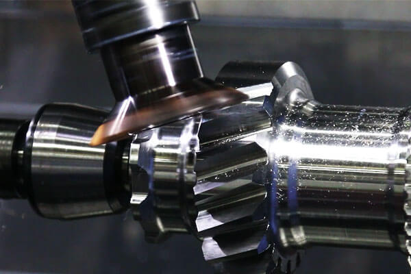
Gear cutting encompasses a range of processes used to produce the teeth of gears, splines, and other toothed components. The two most common methods are hobbing and gear shaping.
- Hobbing: A rotating cutter (the hob) is fed across the rotating workpiece, generating the gear teeth by a continuous cutting action. Hobbing is highly productive and widely used for spur and helical gears.
- Gear Shaping: A reciprocating cutter with the same tooth profile as the gear is pressed into the workpiece, generating teeth one at a time. Shaping is slower but can produce internal gears and some intricate profiles.
Why Gear Cutting Excels:
Gear cutting processes are specifically designed to produce accurate, strong, and quiet-running gear teeth. They are the standard method for manufacturing most gears and splines.
Typical Gear Machining Performance Range
| Parameter | Typical Range | Notes |
| Module / Diametral Pitch | Module 0.5–20+ | Covers small precision gears to large industrial gears. |
| Gear Diameter | 10–1000+ mm | Limited mainly by machine capacity. |
| Tooth Accuracy | ISO Grade 5–8 | Higher grades are used for precision applications. |
| Surface Roughness | Ra 0.8–3.2 μm | Smooth tooth surfaces reduce friction and operating noise. |
| Typical Materials | Carbon steel, alloy steel, stainless steel, cast iron, bronze | Material selection depends on load, speed, and environment. |
Common Gear Cutting and Tooth Profile Machining Methods
| Method | Working Principle | Best Applications |
| Gear Hobbing | A rotating hob cutter continuously generates gear teeth while the workpiece rotates in synchronization. | High-volume production of spur gears, helical gears, and industrial transmission gears. |
| Gear Shaping | A reciprocating cutter generates teeth through synchronized cutting motion. | Internal gears, splines, shoulder gears, and complex gear profiles. |
Broaching |
A multi-tooth broach removes material in a single progressive pass. | High-volume production of internal gears, keyways, and splines. |
| Form Milling | A formed milling cutter cuts individual tooth spaces according to the required profile. | Large gears, small batches, repair work, and custom gear designs. |
| Gear Grinding | An abrasive finishing process removes small amounts of material after heat treatment. | High-precision hardened gears used in automotive, aerospace, and high-performance machinery. |
Practical Tip: Gear hobbing is the most economical method for high-volume gear production. Shaping is used for internal gears and intricate shapes.
Grinding: The Precision Finishing Process
Working Principle:
Grinding uses a rotating abrasive wheel (composed of thousands of hard, sharp grits) to remove material by a combination of cutting, plowing, and rubbing.
The abrasive wheel acts as a multi-tooth cutting tool, but with a negative rake angle, resulting in a very smooth, high-precision surface.
Why Grinding Excels:
Grinding is the process of choice for achieving the highest surface finish and dimensional accuracy, especially on hardened materials (HRC > 45).
It can correct heat treatment distortions and produce flat, parallel surfaces.
| Parameter | Typical Range | Notes |
| Surface roughness | Ra 0.05 – 0.8 µm | Precision grinding can achieve Ra <0.05 µm. |
| Dimensional accuracy | ±0.001 – 0.005 mm | Grinding is the most accurate machining process. |
| Material hardness | Up to 70 HRC | Can grind hardened steels, carbides. |
| Typical materials | Hardened steels, tool steels, carbides, ceramics | All hard, brittle materials. |
Common Grinding Processes:
| Type | Description | Applications |
| Surface grinding | Grinding of flat surfaces. | Mould plates, machine tables, tooling. |
| Cylindrical grinding | Grinding of external cylindrical surfaces. | Shafts, pins, bearing journals. |
| Internal grinding | Grinding of internal cylindrical surfaces. | Bearing housings, cylinder bores. |
| Centreless grinding | Cylindrical grinding without centres. | High-volume shaft production. |
| Tool and cutter grinding | Grinding of cutting tools. | Sharpening drills, end mills, reamers. |
| Creep-feed grinding | Deep, slow-feed grinding. | Complex profiles in hard materials. |
Practical Tip: Grinding generates significant heat, which can cause thermal damage (grinding burn) and residual stress. Use ample coolant and appropriate grinding parameters.
Form Grinding: The Profile Specialisation
Working Principle:
Form grinding uses a shaped grinding wheel or a CNC-controlled process to grind complex, non-linear profiles.
The wheel is dressed to a specific contour, which is then ground into the workpiece.
This is an extension of grinding for specialised applications where a specific shape or profile is required.
Why Form Grinding Excels:
Form grinding can produce very precise, complex profiles in hardened materials, with excellent surface finish and dimensional accuracy.
It is the process of choice for forming dies, punches, and moulds.
Applications:
- Mould cavities
- Die profiles
- Complex contours in tool and die making
- Precision profiles in aerospace components
Practical Tip: Form grinding is a specialised, high-cost process, justified only where extreme accuracy and excellent surface finish are required.
3. The 5 Special Processes: Non-Traditional Machining
Traditional cutting tools struggle—or fail entirely—when faced with very hard materials (tool steels, carbides, ceramics), complex geometries (deep cavities, micro-features), or when thermal or mechanical damage must be minimised.
Special processes use energy forms other than mechanical cutting to remove material, offering solutions to these challenges.
Electrical Discharge Machining (EDM)
Working Principle:
EDM—also known as spark erosion—removes material by a series of rapidly recurring electrical discharges (sparks) between an electrode (tool) and the workpiece.
The sparks erode small amounts of material from both the electrode and the workpiece.
The workpiece is submerged in a dielectric fluid (e.g., deionised water or oil) to control the discharge and flush away eroded particles.

Types of EDM:
| Type | Description | Applications |
| Sinker EDM (Ram EDM) | The electrode is shaped to the negative of the desired cavity. | Mould cavities, die sinking, complex 3D cavities. |
| Wire EDM (WEDM) | A thin, continuously moving wire acts as the electrode. | Profiles, contours, precision parts; blanks for stamping dies. |
| Small-hole EDM | A small-diameter electrode for drilling fine, deep holes. | Cooling holes, fuel injection nozzles. |
Why EDM Excels:
EDM can machine any conductive material, regardless of its hardness. It can produce complex, intricate shapes (including sharp corners) with high accuracy and excellent surface finish.
The process applies no mechanical force, so thin-walled and delicate parts can be machined without distortion.
| Parameter | Typical Range | Notes |
| Surface roughness | Ra 0.2 – 3.2 µm | Depends on finish; excellent for finishing. |
| Dimensional accuracy | ±0.005 – 0.02 mm | High precision, especially in wire EDM. |
| Material hardness | Up to 70 HRC | Virtually unlimited for conductive materials. |
| Material conductivity | Must be electrically conductive. | Not suitable for ceramics, plastics, or glass. |
Applications:
- Mould cavities and dies
- Injection moulds for plastics
- Aircraft engine components
- Medical devices
- Complex contours and profiles
Practical Tip: EDM is a slow process, so it is typically used for finishing operations, not for roughing.
Electrochemical Machining (ECM)
Working Principle:
ECM is a non-traditional machining process that removes material by anodic dissolution. The workpiece (anode) and a shaped tool (cathode) are immersed in an electrolyte.
A high DC current passes between them, and metal ions are dissolved from the workpiece, which are then carried away by the electrolyte flow.
Why ECM Excels:
ECM can machine hard and difficult-to-machine materials with no tool wear and no heat-affected zone.
The process is capable of high material removal rates and can produce complex shapes with good surface finish. It is particularly suited for bulk material removal.
| Parameter | Typical Range | Notes |
| Surface roughness | Ra 0.2 – 0.8 µm | Very good finish. |
| Dimensional accuracy | ±0.05 – 0.2 mm | Lower accuracy than EDM. |
| Material hardness | Up to 70 HRC | Virtually unlimited; material must be conductive. |
| Material removal rate | High | Suitable for bulk removal. |
Applications:
- Jet engine blades and vanes
- Gun barrels (rifling)
- Medical implants
- Moulds for plastics
- Hard, complex aerospace components
Practical Tip: ECM is a specialised process requiring significant investment in equipment and electrolyte handling. It is justified by high production volumes or the difficulty of alternative methods.
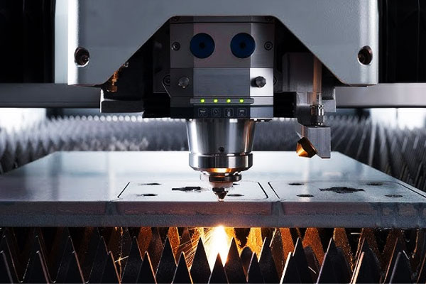
Laser Machining
Working Principle:
Laser machining uses a highly focused beam of coherent light (laser) to melt, vaporise, or ablate material from the workpiece.
The laser spot is moved across the surface using computer-controlled mirrors or motion stages.
Why Laser Machining Excels:
Laser machining is a fast, precise, and contactless process. It can be performed on any material (metals, plastics, ceramics, glass, composites) and can achieve extremely fine features (down to a few microns).
The process does not generate mechanical forces, so thin and delicate parts can be processed.
| Parameter | Typical Range | Notes |
| Kerf width | 0.02 – 0.2 mm | Very narrow cuts. |
| Cutting speed | Up to 50 m/min | High for sheet materials. |
| Feature size | Down to 10 µm | For micro-machining. |
| Material | Virtually any material | Metals, plastics, ceramics, glass. |
| Accuracy | ±0.01 – 0.05 mm | High precision. |
Applications:
- Cutting: sheet metal, profiles, tubes
- Drilling: precision holes, cooling holes
- Engraving and marking: part numbers, logos
- Micro-machining: medical stents, microelectronics
- Surface texturing: creating micro-roughness
Practical Tip: Laser machining generates a heat-affected zone (HAZ). For materials sensitive to thermal damage, consider using short-pulse (picosecond/femtosecond) lasers.
Ultrasonic Machining (USM)
Working Principle:
Ultrasonic machining uses a tool vibrating at high frequency (20-40 kHz) and amplitude (10-50 µm).
An abrasive slurry (e.g., boron carbide or silicon carbide in water) is introduced between the tool and the workpiece.
The vibrating tool impacts the abrasive particles against the workpiece, removing material by micro-chipping and erosion.
Why USM Excels:
USM is the process of choice for machining hard and brittle materials that are difficult or impossible to machine by traditional methods.
It is particularly effective for non-conductive materials (ceramics, glass, stones) and materials with low electrical conductivity.
| Parameter | Typical Range | Notes |
| Surface roughness | Ra 0.2 – 1.6 µm | Good finish. |
| Dimensional accuracy | ±0.005 – 0.02 mm | High precision. |
| Material | Hard, brittle, non-conductive materials | Ceramics, glass, stones, carbides. |
| Tool wear | Moderate | Tools are worn by the abrasive particles. |
Applications:
- Drilling holes in ceramics and glass
- Machining of advanced composites
- Die sinking in hard materials
- Semiconductor and electronics components
Practical Tip: USM is a slow process, so it is typically limited to high-value or difficult-to-machine parts.
Waterjet Machining
Working Principle:
Waterjet machining uses a high-pressure stream of water (with or without abrasive particles) to erode and cut material. Pressures can range from 2,000 to 6,000 bar (30,000 to 90,000 psi).
The water is forced through a small-diameter orifice, creating a supersonic jet that impacts the workpiece.
Why Waterjet Excels:
Waterjet machining is a cold-cutting process—there is no heat-affected zone, no thermal distortion, and no metallurgical changes.
It can cut a wide range of materials, including metals, plastics, glass, composites, and even food.
The process is very flexible, can start anywhere (no pilot hole required), and produces a smooth, accurate edge.
| Parameter | Typical Range | Notes |
| Cutting thickness | Up to 200+ mm | Depending on material and abrasive. |
| Kerf width | 0.5 – 1.5 mm | Narrow. |
| Cutting tolerance | ±0.05 – 0.2 mm | Good accuracy. |
| Surface finish | Ra 0.8 – 6.3 µm | Good finish. |
| No heat-affected zone | Yes | No thermal damage. |
Applications:
- Thick metal plates: aluminium, stainless steel, titanium
- Brittle materials: stone, glass, ceramics
- Composites: laminated materials (no delamination)
- Food processing: cutting food products
- Aerospace components: complex shapes in advanced materials
Practical Tip: Waterjet machining is a powerful and flexible process, but it is relatively slow and generates a large amount of noise and waste slurry.
It is best suited for thick or difficult-to-cut materials where other processes would cause thermal damage.
4. Engineering Guidelines for Selecting Machining Methods
There is no universally perfect machining process. The optimal choice depends on:
- Material properties.
- Part geometry.
- Production volume.
- Accuracy requirements.
- Surface finish requirements.
- Manufacturing cost.
| Application | Recommended Process | Why? |
| Rotational parts (shafts, pins) | Turning | Excellent for cylindrical shapes; good surface finish and accuracy. |
| Flat surfaces, slots, pockets | Milling | Highly versatile; can produce a wide range of shapes. |
| Large, flat surfaces (single parts) | Planing | Low cost for simple parts; good for repair and maintenance. |
| Precise holes | Drilling + Reaming or Boring | Drilling for rough hole; reaming/boring for final size and accuracy. |
| Gear teeth | Hobbing, Shaping | High-volume production; standardised processes. |
Hardened materials (HRC > 45) |
Grinding or EDM | Grinding for flat surfaces; EDM for complex shapes. |
| Complex 3D cavities | EDM or Milling (5-axis) | EDM for deep, intricate shapes; 5-axis milling for larger parts. |
| Very hard, non-conductive materials | Ultrasonic Machining | Ceramics, glass, stones. |
| Thermally sensitive materials | Waterjet Machining | No heat-affected zone; minimal distortion. |
| High precision, small features | Laser Machining | Very fine features, fast, contactless. |
5. Conclusion
The world of machining is vast and complex, but at its core, it is built upon three fundamental material transformation principles—formation, removal, and addition—and a set of well-defined processes that can be matched to specific part requirements.
The 8 traditional processes—turning, milling, planing, drilling, boring, gear cutting, grinding, and form grinding—form the backbone of the manufacturing industry.
They are the workhorses that produce the vast majority of precision components, from simple pins to complex moulds and dies. Their strength lies in their versatility, accuracy, and reliability.
The 5 special processes—EDM, ECM, laser machining, ultrasonic machining, and waterjet machining—provide powerful alternatives when traditional cutting tools reach their limits.
They enable the machining of very hard, brittle, or complex materials, and they can achieve features that would be impossible by conventional methods.
The key to successful process selection lies in understanding the material, the geometry, the production volume, and the required tolerance.
By mastering the characteristics and applications of each process, manufacturing engineers can optimise production efficiency, reduce costs, and achieve superior quality.