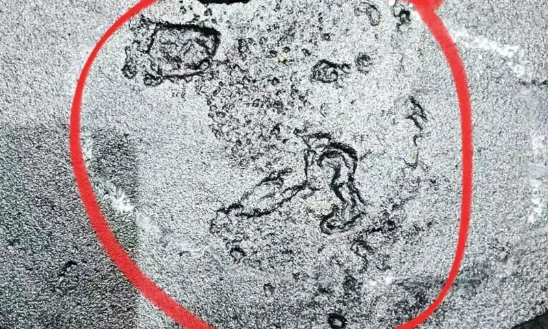
I have been called to more valve flange rejects than I care to count, and the conversation usually starts the same way.
The quality manager holds up a flange, points at the sealing face, and says: “We have cracking. The casting is tearing.”
Nine times out of ten, it is not tearing. It is a wrinkle defect—a surface fold that looks alarming but has a completely different origin and a completely different cure.
If you treat a wrinkle as a hot tear, you will chase pouring temperature and section design for weeks and never fix it.
If you recognize it correctly, you will be looking at the coating, the foam, and the vacuum system within a day.
This article is my field analysis of wrinkle defects on ductile iron valve flanges produced by the lost foam process.
1. How to Identify Wrinkle Defects on Ductile Iron Valve Flanges
Correct defect identification is the first step toward effective process correction. Wrinkle defects can resemble hot tears, cold shuts, or other surface discontinuities, but their appearance and underlying mechanisms are different.
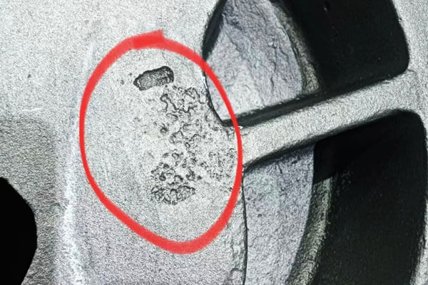
Typical Surface Characteristics
Wrinkle defects on lost foam ductile iron valve flanges commonly exhibit the following characteristics:
- Irregular surface patterns: Continuous, winding, or network-like lines distributed across the flange face.
- Slightly depressed areas: The affected regions may form shallow grooves or uneven surface folds rather than sharp, open cracks.
- Carbonaceous traces: Black or brown residue may be visible along the wrinkle patterns.
- Localized distribution: Defects frequently appear on broad flange sealing faces, thick sections, and local thermal hot spots.
- Removable surface residue: In many cases, grinding removes the carbon-rich surface layer and reveals relatively sound ductile iron underneath.
Because valve flanges provide sealing surfaces for bolted connections, even relatively shallow wrinkles can create machining and inspection problems.
If the defect remains after machining, it may compromise the surface condition required for reliable sealing.
A practical inspection method is to grind a representative section of the affected area.
If grinding removes the pattern and leaves sound metal, you have a wrinkle. If grinding reveals a deep oxidized fracture, you have a hot tear. Do not proceed until you have made this distinction.
2. Formation Mechanism: How EPS Decomposition Produces Wrinkle Defects
Understanding EPS decomposition is essential to controlling wrinkles in lost foam casting.
During pouring, molten ductile iron comes into contact with the EPS foam pattern.
The heat causes the foam to decompose, producing gaseous hydrocarbons, liquid polymer residues, and carbon-rich decomposition products.
These products must pass through or be absorbed by the refractory coating before escaping into the surrounding dry sand and vacuum system.
The coating therefore has two important functions: it must resist the molten metal and maintain sufficient permeability for the removal of gaseous and liquid pattern residues. Both properties are critical to stable lost foam filling.
The Role of the Metal-Coating Interface
As molten iron advances into the mold cavity, it continuously heats and decomposes the foam pattern.
Ideally, the gaseous and liquid decomposition products move through the coating and are evacuated by the negative-pressure system.
However, when the coating has insufficient permeability or the evacuation capacity is inadequate, the decomposition products accumulate near the advancing metal front.
The resulting sequence is typically:
- Molten iron heats and decomposes the EPS pattern.
- Gaseous and liquid decomposition products form at the metal-foam interface.
- The products encounter resistance when passing through the refractory coating.
- Liquid polymer residue and carbon-rich material accumulate locally.
- The advancing metal front moves over or traps the retained residue.
- The retained material produces surface wrinkles, carbonaceous folds, or related surface defects after solidification.
Incomplete pyrolysis and retained carbonaceous residue are established causes of laps and folds in lost foam iron castings.
Why Thick Valve Flanges Are Particularly Vulnerable
The flange section is often thicker than the adjoining valve body wall. This creates a local thermal hot spot with a slower cooling rate and a longer solidification period.
Several conditions can combine in this region:
- The broad flange face provides a relatively large area for coating and pattern interaction.
- Local coating accumulation can increase the distance that decomposition products must travel.
- Thick sections retain heat longer, extending the period during which liquid residue can remain at the metal-coating interface.
- The flange’s position within the mold may create a relatively long or restricted gas-evacuation path.
If the coating and vacuum system cannot remove the decomposition products at the rate they are generated, carbon-rich material may remain trapped against the metal surface.
The result is often a winding wrinkle pattern concentrated on the flange face.
The critical issue is not simply the amount of EPS decomposition gas. It is whether the complete evacuation path—from the metal front through the coating and dry sand to the vacuum outlet—can handle the generated products during filling.
3. Main Causes of Wrinkle Defects in Lost Foam Ductile Iron Valve Flanges
Wrinkle formation is usually the result of several interacting process conditions.
For valve flanges produced with water-based coatings, the investigation should begin with coating drying and permeability before moving to pattern quality, pouring, vacuum, and sand compaction.
3.1 Water-Based Refractory Coating: Inadequate Drying and Low Permeability
Water-based coating problems are among the most important causes to investigate, particularly when wrinkles occur repeatedly on thick flange surfaces.
Incomplete coating drying
Water-based coatings rely on the removal of free moisture before pouring.
A coating that appears dry on the outside may still retain moisture in its internal layer, especially when the applied coating is thick or uneven.
When molten iron enters the mold, residual moisture rapidly vaporizes. The resulting steam increases local gas-generation pressure and can interfere with the movement of EPS decomposition products through the coating.
If the gas-evacuation capacity is insufficient, the metal-coating interface becomes more likely to retain liquid and carbonaceous residues.
This problem is particularly common when production relies on surface appearance rather than confirming that the entire coating layer has dried.
For thick valve flanges, the risk increases when:
- The coating accumulates on the horizontal flange face.
- The coating layer is thicker than on the surrounding pattern.
- Drying time is insufficient for the actual coating thickness.
- Air circulation is poor around recessed or shielded surfaces.
- The production schedule moves patterns to molding before they are fully dry.
Insufficient coating permeability
Even when the coating is completely dry, its permeability may still be inadequate.
An excessively fine refractory powder distribution can reduce the size and connectivity of the pores within the dried coating.
Excessive binder addition may also close effective gas passages after drying and heating.
In some foundries, additional fine refractory powder is added to improve resistance to metal penetration and sand burn-on.
However, if the formulation becomes too dense, the resulting coating may lose the permeability required for removing liquid and gaseous EPS residues.
The coating must therefore balance three properties:
- Refractoriness against molten ductile iron.
- Sufficient strength to protect the foam pattern and resist metal penetration.
- Adequate permeability for decomposition-product evacuation.
Uneven coating thickness on the flange face
During dipping, brushing, or spraying, coating may flow toward the horizontal flange surface and accumulate around the outer edge or recessed areas.
A locally thick coating creates greater resistance to gas and liquid transport than a uniformly applied layer.
As a result, the flange face may become a preferential location for residue accumulation even when the average coating thickness appears acceptable.
Pay particular attention to the back of the flange, bolt-hole surroundings, corners, and transitions between the flange and valve body.
3.2 EPS Foam Pattern Quality
The foam pattern determines the amount and distribution of material that must be decomposed during pouring. Poor pattern quality can increase the burden on the coating and vacuum system.
Excessive EPS pattern density
Higher foam density means more polystyrene material per unit volume. During decomposition, this increases the quantity of polymer products that must be removed from the mold.
In the production conditions described here, an EPS density above 22 kg/m³ should be treated as a warning condition for wrinkle risk, particularly for thick flange patterns with limited gas-evacuation capacity.
This is a process-specific control reference, not a universal density limit for all lost foam castings.
The appropriate density should also satisfy pattern strength, dimensional stability, and handling requirements.
Poor bead fusion
Inadequate fusion between EPS beads can leave internal gaps and an uneven pattern structure.
Such defects may cause nonuniform heating and decomposition, creating irregular gas and liquid-residue release during mold filling.
Poor fusion can also affect the consistency of the coating surface and pattern integrity.
As a result, the coating may not provide uniform coverage, and local decomposition products may encounter different escape conditions.
Pattern density and bead fusion should therefore be controlled together rather than assessed independently.
3.3 Pouring Temperature and Filling Conditions
Pouring temperature and filling behavior strongly influence how quickly the EPS pattern decomposes and how effectively the advancing metal front replaces it.
Pouring Temperature Too Low
Ductile iron lost foam requires a higher pouring temperature than gray iron, because the foam decomposition absorbs heat and because the ductile iron itself has a narrower fluidity window.
In my experience, this often means pouring in the neighborhood of 1,400–1,480°C depending on section thickness, with heavy sections taken toward the upper end.
That is general shop guidance rather than a universal rule—the point is that the temperature must be sufficient for complete pyrolysis.
When the iron temperature is insufficient, the EPS does not decompose completely.
A large amount of viscous liquid residual carbon remains, and it cannot be gasified into small molecules that the vacuum can extract. The residual carbon stays at the interface and forms the wrinkle.
The thick flange hot spot cools slowly, so it might seem that temperature is less critical there.
In practice, the opposite is true: if the incoming metal temperature is inadequate, the problem is amplified precisely because the pyrolysis is incomplete and the residence time is long.
Filling Speed Too Fast
When the iron spreads rapidly across the flange face, it can seal off the coating exhaust path in that region almost instantly.
The foam beneath and behind that sealed area continues to decompose, but its products are now trapped between the metal and the coating with no route out.
Fast filling is often introduced to solve a cold shut or a misrun. It solves that problem and creates this one.
The fill rate has to be matched to the exhaust capacity of the coating, not just to the filling requirement of the cavity.
3.4 Vacuum System and Gas Evacuation
The vacuum system provides the pressure difference needed to move decomposition products through the coating and surrounding dry sand.
Insufficient or unstable negative pressure
If the negative pressure is too low, the system may not provide enough driving force to remove gas and liquid residues from the mold.
Pressure instability during pouring is equally important. A vacuum drop during the filling stage can interrupt gas evacuation just when the EPS decomposition rate is high.
Thick flange regions are particularly vulnerable when they are located far from the nearest effective evacuation path.
Even when the vacuum pump is operating normally, long or restricted flow paths may lead to local evacuation deficiencies.
Inadequate venting behind the flange
If the back of the flange has no dedicated venting path, this region may become a gas-evacuation dead zone.
The gas must then travel through a longer route before reaching the vacuum outlet. If the coating and sand permeability are also low, decomposition products can accumulate near the flange face.
Where the casting design allows, dedicated venting channels or vent ribs should be considered behind the flange and around other difficult-to-evacuate regions.
3.5 Excessive Dry-Sand Compaction
The sand is the last stage of the exhaust path. If it is over-compacted, the path closes.
Over-vibration around the flange face compacts the dry sand, reducing the pore space in the sand layer.
The coating may be perfect and the vacuum may be strong, but the gas still has to travel through the sand to reach the vacuum.
If the sand pores are compressed, the resistance rises, and the extraction at that location becomes insufficient.
The flange face is a large flat area, and it is exactly where operators tend to vibrate thoroughly to ensure good sand support. The intention is good. The result is a blocked exhaust path.
The rule I give is: compact enough to support the pattern, not so much that you close the sand.
4. Differential Diagnosis: Wrinkle vs. Hot Tear vs. Other Surface Defects
Getting the diagnosis right is more than half the work. The table below is the one I use at the bench.
| Defect | Appearance | Grinding Behavior | Root Cause |
| Wrinkle | Network, meandering, depressed, carbon traces | Carbon removed, matrix intact | EPS pyrolysis products trapped at interface |
| Hot tear | Linear, open, sharp-edged | Crack remains, oxidized | Restraint during solidification contraction |
| Burn-on / penetration | Rough, sandy, metal-shell fusion | Difficult to remove, shell bonded | Coating refractory failure, high pouring temperature |
| Gas porosity | Round holes, subsurface | Cavity remains | Gas entrapment or moisture |
| Cold shut | Linear seam, poor fusion | Seam remains | Low pouring temperature, slow fill |
The three-step self-check:
- Grind the patterned area. If the carbon pattern is removable and the ductile iron matrix below is sound, it is a wrinkle.
- If grinding reveals metal cracking, deep gaps, and an oxidized fracture surface, it is a hot tear—a different defect with a different cause.
- If the surface is rough and sandy, and grinding reveals shell material fused to the metal, it is burn-on or penetration, not a wrinkle.
Do not skip this step. The corrective actions for the three defects overlap only partially.
5. Water-Based vs. Alcohol-Based Coatings: Different Wrinkle Risks
Water-based and alcohol-based refractory coatings have different drying and high-temperature behaviors.
Therefore, their dominant causes of wrinkle defects are not the same. When switching between coating systems, foundries should adjust their process controls accordingly rather than applying the same corrective measures.
Water-based coatings:
The primary risk is incomplete drying and residual moisture inside the coating layer. Even when the surface appears dry, moisture may remain in the inner layer.
During pouring, this moisture vaporizes and can obstruct the coating’s micropores, significantly reducing effective permeability.
As a result, EPS decomposition products cannot escape efficiently and may accumulate at the metal-coating interface, forming carbonaceous wrinkles.
Alcohol-based coatings:
The main risk is excessive sintering after ignition. If the coating receives excessive heat, its refractory particles may become over-sintered, forming a dense, glassy layer.
This reduces pore connectivity and restricts the escape of EPS decomposition products.
Although the final result is similar to that of water-based coating defects, the underlying cause is thermal over-densification rather than residual moisture.
The corrective measures must therefore match the coating system. For water-based coatings, prioritize complete drying and moisture verification.
For alcohol-based coatings, focus on controlling ignition and sintering conditions, together with optimizing the coating formulation.
6. Practical Solutions: How to Eliminate Wrinkle Defects
For water-based coating systems, the most effective corrective strategy is to address the coating condition first, then verify pattern quality, pouring stability, vacuum performance, and dry-sand permeability.
Changing several parameters simultaneously makes it difficult to identify the actual cause.
A controlled adjustment sequence is more reliable and helps prevent the same defect from recurring in subsequent production batches.
Priority 1: Ensure Complete Drying of the Water-Based Coating
Coating drying should be the first corrective action when wrinkle defects appear repeatedly on valve flange faces.
The objective is to remove residual moisture from the entire coating layer, not merely produce a dry-looking surface.
Recommended measures include:
- Establish controlled drying temperature and holding time according to coating thickness, pattern geometry, and coating supplier requirements.
- Ensure sufficient hot-air circulation around the flange face, back surface, bolt holes, and recessed areas.
- Avoid moving patterns into the molding operation before the coating has dried completely.
- Check residual moisture periodically, especially on thick flange sections and other areas where coating tends to accumulate.
- Prevent excessive coating buildup during dipping or brushing.
- Maintain consistent drying conditions between production batches.
A common mistake is to use the same drying time for every pattern, regardless of coating thickness and geometry.
Thick flange sections, recessed areas, and locally accumulated coatings may require more time to dry thoroughly.
Practical recommendation: Establish a specific drying inspection point for the flange face. Confirm that the coating is dry through its thickness before the pattern enters the molding line.
Priority 2: Optimize Coating Formulation and Permeability
After confirming complete drying, evaluate whether the coating can evacuate the volume of decomposition products generated by the EPS pattern.
The main objective is to maintain sufficient gas permeability without sacrificing refractory protection.
Recommended adjustments include:
- Optimize refractory aggregate particle-size distribution.
- Introduce an appropriate proportion of coarser refractory particles to maintain interconnected pores.
- Control binder addition to avoid excessive pore closure after drying and heating.
- Maintain stable slurry viscosity and density.
- Avoid excessive fine-powder loading.
- Test coating permeability and coating thickness under controlled production conditions.
The balance between refractory protection and permeability is particularly important for ductile iron because the foam generates a substantial volume of decomposition products during high-temperature filling.
A coating that is too porous may increase the risk of metal penetration, burn-on, or sand-related surface defects. A coating that is too dense may restrict gas evacuation and promote wrinkles.
The correct formulation must provide both adequate refractoriness and sufficient permeability.
Priority 3: Improve EPS Pattern Density and Bead Fusion
The EPS pattern should generate a manageable volume of decomposition products and maintain a uniform surface structure.
The following controls are recommended:
- Keep EPS density within the qualified range for the casting.
- Treat density above 22 kg/m³ as a warning condition under the production conditions discussed here.
- Check bead fusion quality during pattern inspection.
- Reject patterns with obvious internal gaps, poor fusion, or local deformation.
- Maintain consistent foam molding conditions.
- Inspect adhesive joints between pattern sections for excessive adhesive accumulation or incomplete bonding.
For thick valve flanges, pay particular attention to the pattern density and fusion quality around the flange body and transitions.
A small variation in pattern quality can become more significant when the coating and vacuum system are already operating close to their evacuation limits.
Priority 4: Stabilize Pouring Temperature and Filling Speed
Pouring parameters should be reviewed after coating and foam-pattern conditions have been verified.
Pouring temperature:
Confirm that the actual iron temperature at pouring meets the qualified process requirement for the ductile iron grade and casting structure.
Avoid excessively low temperatures that reduce fluidity and hinder pattern replacement.
At the same time, do not rely on excessive superheat to compensate for poor coating permeability or inadequate vacuum.
Pouring speed:
Maintain a continuous and stable metal stream. Avoid abrupt acceleration that causes turbulent filling or rapidly seals off local gas-evacuation paths.
Equally, avoid unnecessarily slow pouring that allows the metal front to cool and lose filling capacity.
Gating design:
Review the ingate position and filling sequence around the flange.
The gating system should promote controlled metal-front progression and minimize turbulence, premature metal-front convergence, and local accumulation of decomposition products.
For recurring flange-face wrinkles, a useful approach is to compare the filling behavior and defect distribution before and after controlled gating or pouring adjustments.
Priority 5: Maintain Stable Vacuum Throughout Pouring
The vacuum system must provide sufficient and continuous evacuation capacity during the entire filling operation.
Recommended measures include:
- Monitor negative pressure throughout pouring rather than checking only the initial vacuum reading.
- Inspect vacuum pipelines, seals, filters, and connections for leakage or blockage.
- Check whether vacuum pressure drops during the initial or middle stages of filling.
- Review the location and number of vacuum connections.
- Add vent ribs or dedicated venting channels behind the flange where the existing arrangement creates a gas-evacuation dead zone.
- Verify that the venting system can handle the decomposition-product volume generated by the complete pattern.
The required negative-pressure setting should be established through production trials.
Simply increasing vacuum is not always the correct solution, because the result also depends on coating permeability, dry-sand condition, flask configuration, and pattern geometry.
For thick flange regions located far from the vacuum outlet, improving the venting route may be more effective than making a general adjustment to the vacuum setting.
Priority 6: Control Dry-Sand Compaction Around the Flange
The dry sand surrounding the coating must remain sufficiently permeable for decomposition products to travel toward the vacuum system.
For flange regions, the following measures are recommended:
- Avoid excessive vibration around broad flange faces.
- Maintain uniform sand filling around the pattern.
- Prevent local overcompaction near venting channels.
- Check whether the vibration process creates significant differences in sand density between the flange and valve body.
- Maintain sufficient compaction to support the pattern and prevent mold deformation.
The aim is not to minimize vibration. Undercompaction can cause pattern movement, dimensional instability, or mold collapse.
Instead, vibration should provide adequate pattern support while preserving interconnected gas-flow passages within the sand.
7. Conclusion
Wrinkle defects in lost foam ductile iron valve flanges are primarily associated with the retention of EPS decomposition products at the metal-coating interface.
Thick flange sections are particularly vulnerable because their geometry, coating distribution, and longer thermal exposure can make gas and liquid-residue evacuation more difficult.
For foundries using water-based coatings, complete coating drying should be the first control priority.
Insufficient coating permeability, excessive EPS density, poor bead fusion, unsuitable pouring conditions, unstable vacuum, and excessive dry-sand compaction are additional factors that must be evaluated together.
At LangHe, effective defect prevention requires more than adjusting pouring temperature or increasing vacuum.
The entire process—from EPS pattern preparation and coating application to drying, mold compaction, vacuum evacuation, and metal filling—must operate as a coordinated system.
Fix the exhaust path, and the wrinkle disappears. That is the whole discipline of lost foam casting in one sentence.
FAQs
How do I tell a wrinkle from a hot tear?
Grind the defect. If the carbon pattern is removed and the matrix is sound, it is a wrinkle.
If the grinding reveals an open, deep, oxidized metal crack, it is a hot tear. The two defects have different causes and different corrective actions.
Why is the flange face the most common location for wrinkles?
The flange is a thick hot spot that solidifies slowly, giving pyrolysis products a long residence time.
The flange face is also a large flat area where coating tends to pool and thicken, increasing exhaust resistance. The exhaust path is also longest at the far end of the flange.
Why does pouring temperature matter for wrinkle defects?
Ductile iron lost foam requires a higher pouring temperature than gray iron.
If the temperature is insufficient, EPS decomposition is incomplete and a large amount of viscous liquid residual carbon remains, which cannot be gasified into small molecules for vacuum extraction.
Why does over-vibrating the sand cause wrinkles?
Over-vibration compacts the dry sand around the flange face, reducing the pore space in the sand layer.
The gas has to travel through the sand to reach the vacuum, and if the sand pores are compressed, the resistance rises and extraction becomes insufficient.