编辑翻译
经过 Transposh - translation plugin for wordpress
What Is Computer Aided Design

What Is Computer Aided Design?

内容表 展示

Computer Aided Design (卡德) has revolutionized the way products are conceived, developed, analyzed, 并制造.

From consumer electronics and medical devices to aircraft, 汽车, 和工业机械, nearly every modern engineered product begins as a digital CAD model.

More than simply replacing paper drawings, CAD has become the digital foundation of modern engineering.

A single CAD model can support visualization, structural simulation, manufacturing planning, cost estimation, quality inspection, and even product lifecycle management (PLM).

作为行业 4.0, 数字双胞胎, 人工智能 (人工智能), and additive manufacturing continue to evolve, CAD is becoming increasingly intelligent and interconnected across the entire manufacturing ecosystem.

1. What Is Computer Aided Design (卡德)?

Computer Aided Design (卡德) is the use of computer software to create, modify, analyze, optimize, and document the design of physical products or engineering systems.

Unlike traditional drafting, CAD enables designers to build precise digital models that accurately represent a product’s geometry, dimensions, 材料, 公差, and functional characteristics.

These digital models serve as the authoritative source of engineering data throughout the product development process.

Computer-Aided Design is used by professionals across numerous disciplines, 包括:

  • 机械工业
  • Industrial design
  • 建筑学
  • Civil engineering
  • Aerospace engineering
  • Automotive engineering
  • Electrical engineering
  • Medical device development
  • Consumer product design
计算机辅助设计
计算机辅助设计

Core Functions of Computer Aided Design

Modern CAD systems extend far beyond simple drafting. They provide an integrated platform supporting the entire engineering design process.

The primary capabilities include:

  • Two-dimensional drafting
  • Three-dimensional solid modeling
  • Surface modeling
  • Assembly design
  • Parametric modeling
  • Dimensioning and tolerancing
  • Engineering drawing generation
  • Motion simulation
  • 有限元分析 (fea) 一体化
  • Manufacturing data preparation
  • Product visualization
  • Design collaboration
  • Product lifecycle integration

2. The Evolution of Computer Aided Design

The history of Computer-Aided Design reflects the broader evolution of digital engineering.

Manual Drafting Era

Before computers became widely available, technical drawings were created entirely by hand.

Design revisions often required redrawing entire sheets, making product development slow and expensive.

Early Computer Graphics (1960s)

One of the earliest milestones was Sketchpad, developed by Ivan Sutherland in 1963.

Sketchpad introduced interactive computer graphics, geometric constraints, and object-based modeling, laying the foundation for modern CAD systems.

Commercial Computer-Aided Design Systems (1970s–1980s)

As computing power increased, commercial CAD software emerged for industries such as aerospace and automotive manufacturing.

These early systems dramatically improved drafting efficiency but remained expensive and accessible only to large enterprises.

Parametric Modeling Revolution (1990s)

The introduction of parametric solid modeling transformed product design.

Instead of editing individual drawing elements, designers could define relationships between features, allowing models to update automatically whenever dimensions or parameters changed.

This innovation significantly improved engineering productivity and design consistency.

Cloud and AI-Driven CAD (今天)

Modern Computer Aided Design platforms increasingly integrate:

  • Cloud collaboration
  • 人工智能
  • Generative design
  • 模拟
  • Digital twins
  • Manufacturing automation

Today’s CAD systems have evolved into comprehensive engineering platforms rather than standalone drawing tools.

3. How Computer Aided Design Works

计算机辅助设计 (卡德) is much more than a digital drawing tool.

It is an integrated engineering platform that transforms design concepts into intelligent digital models capable of supporting the entire product development process—from conceptual design and engineering analysis to manufacturing, 检查, and product lifecycle management.

From Design Concept to Digital Model

Every Computer-Aided Design project begins with a design objective.

Engineers first define the product’s functional requirements, 工作条件, 材料选择, 制造过程, 和性能目标.

These design inputs determine the overall geometry and structural configuration of the component.

The modeling process typically starts with a two-dimensional sketch created on a reference plane. Unlike traditional drawings, a CAD sketch is not simply a collection of lines.

反而, it is a fully constrained geometric framework where dimensions, 角度, 半径, tangency conditions, 对称, and positional relationships are mathematically defined.

Once the sketch is fully constrained, it serves as the foundation for generating three-dimensional geometry through operations such as extrusion, revolution, sweeping, lofting, or boundary surface creation.

These features gradually build the complete digital representation of the product while preserving precise dimensional relationships.

Because every feature remains associated with the underlying design parameters, modifications can be made quickly without rebuilding the entire model.

Parametric Modeling and Design Intent

One of the most powerful capabilities of modern CAD software is parametric modeling, which allows engineers to define products based on engineering relationships rather than fixed geometry.

In a parametric model, dimensions are treated as editable variables. Features are linked together through constraints that reflect the intended design logic.

When one dimension changes, all dependent features update automatically while maintaining the original design intent.

例如, increasing the diameter of a shaft can automatically adjust the size of mating holes, 轴承座, 键盘, and associated assemblies without requiring manual modification of each individual feature.

This approach offers several important advantages:

  • Rapid design iteration
  • Reduced modeling errors
  • Improved design consistency
  • Easier product customization
  • Efficient creation of product families

Parametric modeling is particularly valuable in industries where products exist in multiple sizes or configurations, allowing manufacturers to generate new variants by modifying only a small number of key parameters.

Feature-Based Solid Modeling

Rather than constructing complex shapes as a single object, modern Computer-Aided Design software builds models using a sequence of engineering features.

Each feature represents a manufacturing or functional operation, such as adding a boss, creating a hole, cutting a pocket, applying a fillet, or forming a rib.

These features are organized within a feature history tree that records the complete modeling process.

This history-based approach allows engineers to return to any stage of the design and modify earlier features without recreating the entire model.

Because subsequent features automatically regenerate, design revisions become significantly faster and more reliable.

Feature-based modeling also mirrors real manufacturing processes, making it easier for production engineers to understand how components will be fabricated.

Assembly Modeling and Motion Simulation

Most engineering products consist of multiple interconnected components rather than individual parts.

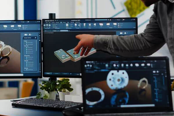
Computer-Aided Design software therefore provides comprehensive assembly modeling capabilities that enable designers to combine individual components into complete mechanical systems.

During assembly creation, engineers define geometric relationships such as concentricity, coincidence, 结盟, offsets, and rotational constraints.

These relationships ensure that components are positioned correctly and function together as intended.

Modern CAD platforms also support motion simulation, allowing engineers to evaluate how assemblies behave under operating conditions before physical prototypes are produced.

Motion analysis can identify:

  • Mechanical interference
  • Collision between moving parts
  • Range of motion limitations
  • Assembly sequence issues
  • Kinematic performance

By detecting these problems during the digital design stage, manufacturers can avoid costly modifications later in production.

Engineering Analysis and Design Verification

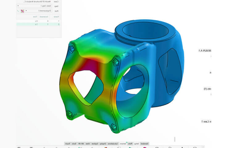
A CAD model is far more than a visual representation—it also serves as the foundation for engineering analysis.

Many modern CAD platforms integrate Computer-Aided Engineering (计算机辅助工程) tools that allow designers to evaluate product performance before manufacturing begins.

Instead of relying solely on physical testing, engineers can simulate real-world operating conditions within the digital environment.

Common analyses include structural stress, 形变, 振动, thermal distribution, 流体流动, 疲劳生活, and buckling behavior.

These simulations enable engineers to optimize designs by identifying weak areas, reducing unnecessary material, improving safety factors, and enhancing product reliability while minimizing the need for expensive prototype testing.

设计可制造性 (DFM)

Effective Computer-Aided Design modeling extends beyond product functionality—it also considers how the component will be manufactured.

Modern CAD systems support Design for Manufacturability (DFM) by helping engineers evaluate whether a design can be produced efficiently using processes such as CNC machining, 投资铸造, 注入成型, 钣金制造, 或添加剂制造.

例如, CAD software enables designers to assess draft angles for molded components, minimum wall thickness for castings, machining accessibility, hole depths, corner radii, and machining tool clearances.

By incorporating manufacturing considerations during the design stage, companies can significantly reduce production costs, minimize design revisions, and improve product quality.

4. Types of Computer-Aided Design Software

Computer-Aided Design software has evolved into a diverse ecosystem tailored to different engineering disciplines, 行业, and stages of product development.

While all CAD systems share the common objective of creating accurate digital models, they differ considerably in their modeling philosophy, computational capabilities, collaboration features, and integration with manufacturing and simulation tools.

Computer Aided Design

2D Drafting Computer Aided Design

Two-dimensional CAD software focuses on creating engineering drawings composed of lines, arcs, dimensions, symbols, and annotations.

Although modern engineering increasingly relies on three-dimensional modeling, 2D drafting remains indispensable for manufacturing documentation, plant layouts, piping diagrams, electrical schematics, and legacy drawing revisions.

Compared with manual drafting, 2D CAD significantly improves drawing accuracy, revision speed, and document management.

Layers, reusable blocks, dimension styles, and automated scaling greatly simplify the preparation of standardized technical drawings.

典型的应用包括:

  • Manufacturing drawings
  • Architectural floor plans
  • Structural layouts
  • Electrical wiring diagrams
  • Hydraulic and pneumatic schematics
  • Process flow diagrams (PFD)
  • Piping and Instrumentation Diagrams (p&ID)

The most widely recognized software in this category is AutoCAD, which has remained an industry standard for decades.

3D Parametric Computer Aided Design

Parametric modeling represents the dominant approach in modern mechanical engineering.

Unlike static geometric modeling, parametric CAD records every modeling operation and maintains relationships between features, dimensions, and design constraints.

Design modifications propagate automatically throughout the model.

例如, increasing the thickness of a mounting plate automatically updates hole depths, fastener lengths, assembly clearances, mass properties, and associated engineering drawings.

This capability dramatically reduces redesign time and minimizes inconsistencies during product revisions.

Because engineering intent is embedded within the model, parametric CAD is particularly suitable for products that undergo frequent design optimization or require multiple configuration variants.

Representative software includes:

软件 典型行业 关键优势
SolidWorks Mechanical equipment, 机械 User-friendly parametric modeling
Creo 航天, 汽车 Advanced engineering capabilities
Autodesk Inventor 工业机械 Integrated mechanical design
Solid Edge 制造业 Synchronous and parametric modeling
CATIA 航天, 汽车 Large assembly management and complex surfaces
Siemens NX High-end manufacturing Integrated CAD, 凸轮, and CAE platform

Direct Modeling Computer Aided Design

Direct modeling eliminates the dependency on feature history. Instead of editing parameters recorded during model creation, engineers modify geometry directly by pushing, pulling, offsetting, or deleting faces.

This modeling approach offers exceptional flexibility when working with imported models lacking editable feature trees.

It is particularly valuable during conceptual design, rapid engineering modifications, reverse engineering, and collaborative projects involving multiple CAD platforms.

Although direct modeling provides greater freedom, it generally sacrifices some of the automation and design intent preservation offered by parametric systems.

最后, many modern CAD platforms combine both methodologies, allowing engineers to choose the most appropriate workflow for a given task.

Surface Modeling Computer Aided Design

Surface modeling specializes in generating highly complex freeform geometries that cannot be efficiently represented using conventional solid features.

Instead of describing an object’s volume, surface modeling defines its external boundaries using mathematically continuous surfaces such as NURBS (Non-Uniform Rational B-Splines).

Designers manipulate curvature, 连续性, and control points to achieve exceptionally smooth transitions between adjacent surfaces.

This technology is widely used where aerodynamic efficiency or aesthetic appearance is critical.

典型的应用包括:

  • Automotive exterior panels
  • Aircraft fuselages
  • 消费电子产品
  • 医疗植入物
  • Industrial design
  • 家用电器

Because even minor discontinuities may affect both appearance and performance, advanced surface modeling tools provide precise control over curvature continuity (G0, G1, G2, and higher-order continuity).

Freeform and Industrial Design Computer Aided Design

Industrial designers often require greater artistic freedom than conventional engineering CAD systems provide.

Freeform modeling software bridges the gap between artistic creativity and engineering precision.

Rather than relying solely on engineering dimensions, designers sculpt digital geometry using subdivision surfaces, control cages, and organic modeling techniques.

The resulting forms can later be converted into manufacturable engineering models.

These systems are commonly employed during the conceptual development of products where ergonomics and visual appeal are primary considerations, such as consumer electronics, 家具, 体育用品, and automotive interiors.

Building Information Modeling (BIM)

Although technically distinct from traditional mechanical CAD, Building Information Modeling represents the CAD standard within architecture, 工程, 和施工.

Unlike ordinary geometric models, BIM objects contain extensive engineering information including material specifications, structural properties, fire ratings, maintenance schedules, construction sequencing, and lifecycle costs.

As the building model evolves, all associated floor plans, elevations, 部分, schedules, and quantity takeoffs update automatically, greatly improving coordination among architects, structural engineers, and construction contractors.

Leading BIM platforms include Autodesk Revit, ArchiCAD, and Bentley OpenBuildings.

Electrical and Electronic Computer Aided Design (ECAD)

Electronic product development relies on specialized CAD software optimized for electrical and electronic design rather than mechanical geometry.

ECAD systems support:

  • Schematic capture
  • 印刷电路板 (PCB) layout
  • Signal integrity analysis
  • Component libraries
  • Routing optimization
  • Manufacturing documentation

Modern electronic products increasingly require collaboration between ECAD and mechanical CAD systems to ensure enclosure compatibility, connector alignment, 热管理, and electromagnetic shielding.

Cloud-Based Computer-Aided Design

Cloud computing has transformed CAD from a workstation-dependent application into a collaborative engineering platform accessible through standard web browsers.

Instead of storing design files locally, cloud-based systems maintain centralized databases that support real-time collaboration among geographically distributed engineering teams.

Engineers can simultaneously review assemblies, implement design changes, track revisions, and manage product data without exchanging multiple file versions.

Automatic version control reduces the risk of conflicting modifications while simplifying project management.

Cloud CAD is particularly attractive for multinational organizations, startups, and distributed manufacturing networks because it lowers hardware requirements and facilitates secure collaboration across different locations.

5. Computer Aided Design File Formats

Selecting the correct file format is critical for collaboration and manufacturing.

File Format 典型用途
步 (.stp, .步) Universal 3D data exchange for manufacturing
IGES (.igs) Surface geometry exchange
Parasolid (.x_t, .x_b) Solid modeling kernel exchange
STL 3D printing and rapid prototyping
DWG 2D drafting
DXF CAD data exchange
SLDPRT SOLIDWORKS part file
SLDASM SOLIDWORKS assembly
CATPart CATIA model
IPT Autodesk Inventor part

Among these formats, is generally regarded as the preferred choice for CNC machining, 投资铸造, and precision manufacturing because it preserves accurate solid geometry while remaining software-independent.

6. Where Is Computer Aided Design Used in Modern Manufacturing?

计算机辅助设计 (卡德) has become the digital foundation of modern manufacturing.

Regardless of whether a product is produced by machining, 铸件, 成型, 增材制造, or sheet metal fabrication, nearly every manufacturing process begins with a CAD model.

It serves as the primary source of engineering data, providing the geometry, dimensions, 公差, material specifications, and manufacturing information required throughout the entire production lifecycle.

计算机辅助设计
计算机辅助设计

Product Design and Engineering Development

The earliest application of CAD is product design itself. Engineers use CAD software to transform ideas into fully defined three-dimensional models that accurately represent a product’s geometry and functional characteristics.

During the design stage, components are created using parametric features that can be modified efficiently as product requirements evolve.

Designers evaluate dimensions, wall thicknesses, clearances, assembly relationships, and material distribution long before any physical prototype is manufactured.

This digital approach enables rapid design iteration while significantly reducing development time and engineering costs.

Because every modification is reflected throughout the model automatically, engineering changes can be implemented with far greater efficiency than traditional drafting methods.

For companies developing new products, CAD provides a collaborative environment where industrial designers, mechanical engineers, electrical engineers, and manufacturing specialists can simultaneously contribute to product optimization.

数控加工

Computer Aided Design plays a central role in 数控加工 because every machining operation begins with an accurate digital model.

Once the Computer-Aided Design model is completed, it is transferred to CAM software, where machining strategies and toolpaths are generated automatically.

The software determines cutter movement, 主轴速度, 饲料率, cutting depth, and machining sequence based on the component geometry.

The accuracy of the CAD model directly influences machining quality.

Features such as holes, 口袋, 鱼片, Chamfers, threaded sections, and complex curved surfaces are interpreted directly from the model, minimizing programming errors and improving machining efficiency.

CAD also allows engineers to evaluate manufacturability before machining begins.

Features that may increase machining difficulty, such as deep cavities, sharp internal corners, or inaccessible cutting areas, can be identified and optimized during the design stage, reducing production costs and shortening lead times.

Precision Casting and Investment Casting

熔模铸造 is one of the manufacturing processes that benefits most from Computer Aided Design technology.

Complex stainless steel, 铝, 钛, and superalloy components are first modeled digitally before patterns and tooling are produced.

Because investment casting can accurately reproduce intricate geometries, CAD allows engineers to fully utilize the process’s design flexibility by incorporating thin walls, 内部段落, complex curves, and integrated structures into a single casting.

In addition to defining component geometry, CAD supports the design of gating systems, 跑步者, 立管, and feeding solutions that influence metal flow and solidification behavior.

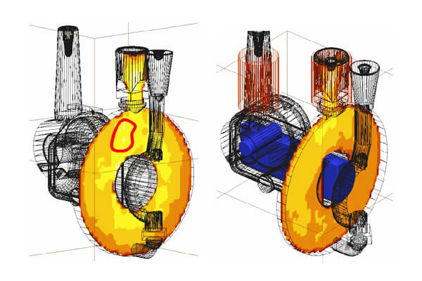
The digital model also serves as the basis for casting simulation software, enabling engineers to predict filling patterns, 收缩, 孔隙率, and other potential defects before production begins.

This integration significantly reduces tooling modifications and improves first-pass casting quality.

Sand Casting and Lost Foam Casting

Computer-Aided Design has also transformed conventional casting technologies such as sand casting and lost foam casting.

为了 沙子铸造, digital models are used to design patterns, 内核, 芯盒, and molding equipment while ensuring appropriate machining allowances, 草稿角, and shrinkage compensation.

In lost foam casting, CAD enables engineers to create highly accurate foam patterns that replicate the final component geometry.

Complex assemblies can often be integrated into a single foam pattern, reducing assembly operations and improving casting consistency.

Simulation tools linked to CAD models further assist in optimizing mold filling, 气体排出, 和凝固行为, helping foundries minimize casting defects while improving production efficiency.

Injection Molding and Plastic Product Development

In plastic 注入成型 制造业, Computer Aided Design serves as the foundation for both product design and mold development.

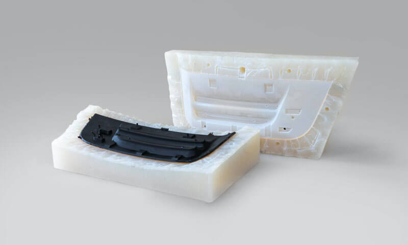
Engineers use CAD models to optimize wall thickness, rib placement, 老板, snap-fit features, 草稿角, and parting lines before tooling is manufactured.

Since mold construction represents a significant investment, identifying design issues early can prevent expensive tooling modifications later in the project.

Modern CAD systems also integrate mold flow simulation, allowing designers to analyze polymer filling behavior, cooling efficiency, weld lines, air traps, 水槽标记, and warpage.

By validating designs digitally, manufacturers can reduce trial-and-error during mold commissioning while improving final product quality.

钣金加工

钣金 manufacturing requires careful consideration of material behavior during 弯曲 and forming operations.

CAD software enables engineers to design three-dimensional sheet metal components while automatically generating accurate flat patterns for laser cutting or punching.

The software accounts for bend allowance, bend deduction, material thickness, and forming radius, ensuring that the finished component matches the intended design after bending.

This capability greatly reduces production errors and minimizes material waste, particularly in industries such as automotive manufacturing, 电气外壳, HVAC系统, 和工业设备.

Additive Manufacturing and 3D Printing

The rapid growth of additive manufacturing has further expanded the importance of Computer Aided Design.

Unlike subtractive manufacturing processes that remove material, 3D打印 builds components layer by layer directly from digital models.

Every printed component begins as a CAD file, which defines both the external geometry and increasingly sophisticated internal structures.

Modern CAD software supports advanced design approaches that are uniquely suited to additive manufacturing, including lattice structures, topology optimization, 共形冷却通道,

and lightweight cellular geometries that would be impossible to produce using traditional manufacturing methods.

As additive manufacturing continues to mature, CAD is becoming an increasingly powerful tool for designing components specifically optimized for layer-based production.

Assembly Design and System Integration

Modern products rarely consist of a single component. 反而, they are assembled from dozens, hundreds, or even thousands of individual parts that must function together precisely.

CAD assembly modeling allows engineers to evaluate component fit, movement, 干涉, fastening methods, and maintenance accessibility before manufacturing begins.

Virtual assembly environments help identify dimensional conflicts, collision risks, and installation issues during product development, significantly reducing costly assembly modifications during production.

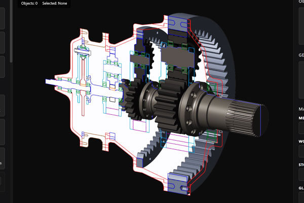
Motion simulation capabilities further allow engineers to evaluate mechanisms, gear systems, 联系, 铰链, and rotating assemblies under realistic operating conditions.

Smart Manufacturing and Digital Twins

作为行业 4.0 technologies become increasingly widespread, CAD is evolving into the central data source for intelligent manufacturing systems.

A modern CAD model no longer serves only as a design document—it forms the foundation of digital twins that connect virtual products with real-world operational data.

Throughout a product’s lifecycle, CAD models may be linked with manufacturing execution systems (Mes), enterprise resource planning (ERP), IoT sensors, and PLM platforms to create a continuously updated digital representation of the physical product.

This integration enables predictive maintenance, real-time performance monitoring, 过程优化, and lifecycle management, allowing manufacturers to make better decisions based on accurate engineering data.

7. Benefits of Computer-Aided Design

计算机辅助设计 (卡德) has transformed modern product development by improving design accuracy, engineering efficiency, and manufacturing integration.

Compared with traditional manual drafting, CAD enables engineers to create precise digital models that support every stage of a product’s lifecycle, from concept design to production and quality control.

Higher Accuracy and Design Quality

Computer Aided Design uses mathematical models to define geometry, dimensions, and tolerances with high precision.

Unlike manual drawings, digital models maintain consistency throughout the design process, reducing human error and improving product quality.

Faster Product Development

Design changes can be made quickly using parametric modeling, allowing engineers to update dimensions and features without rebuilding the entire model. This shortens development cycles and enables faster design iterations.

Better Visualization and Communication

Three-dimensional CAD models provide realistic visualization of products, making it easier to review designs, identify potential issues, and communicate ideas among designers, 工程师, 制造商, and customers.

Improved Design for Manufacturability

CAD helps engineers optimize products for manufacturing by evaluating factors such as wall thickness, 草稿角, machining accessibility, and assembly requirements during the design stage.

This reduces production costs and minimizes design changes later.

Integration with Simulation and Manufacturing

Modern CAD software integrates seamlessly with Computer-Aided Engineering (计算机辅助工程) and Computer-Aided Manufacturing (凸轮).

Engineers can perform structural, 热的, and motion simulations directly on CAD models before generating CNC toolpaths, 模具, or 3D printing files, improving both product performance and manufacturing efficiency.

Enhanced Collaboration

Cloud-based CAD platforms allow multiple teams to work on the same digital model while maintaining version control.

This improves collaboration across design, 工程, 制造业, and quality departments.

Better Quality Control

Computer-Aided Design models serve as reference data for inspection equipment such as Coordinate Measuring Machines (CMM) and 3D scanners.

Comparing finished parts with the original CAD model helps ensure dimensional accuracy and consistent product quality.

Lower Overall Development Costs

Although CAD requires investment in software and training, it reduces engineering time, minimizes physical prototyping, lowers manufacturing errors, and shortens time-to-market.

These advantages significantly reduce the total lifecycle cost of product development.

8. What Are the Most Popular Computer Aided Design Software and Tools?

A wide range of CAD software is available today, each designed to meet the needs of different industries, 设计复杂性, and manufacturing workflows.

CAD Software Developer 主要应用 关键功能 最好的
AutoCAD Autodesk 2D drafting, basic 3D modeling Industry-standard drafting, DWG support, extensive documentation tools Architects, civil engineers, general drafting
SolidWorks Dassault Systèmes Mechanical design, 产品开发 Parametric modeling, 组件, 模拟, 金属板, weldments Mechanical engineering and manufacturing
Autodesk Inventor Autodesk 机械工业 Parametric design, assembly modeling, 模拟, 工具设计 Industrial machinery and manufacturing
融合 360 Autodesk Product design, 数控加工, 3D打印 Cloud collaboration, CAD/CAM/CAE integration, generative design Startups, 中小型企业, 原型
CATIA Dassault Systèmes 航天, 汽车, 工业设备 Advanced surface modeling, large assemblies, systems engineering 航空航天和汽车工业
Siemens NX Siemens Digital Industries Software High-end product engineering Integrated CAD, 凸轮, 计算机辅助工程, digital twin, 高级模拟 航天, 汽车, high-end manufacturing
PTC Creo
PTC Mechanical product design Parametric and direct modeling, 模拟, 增材制造 Complex mechanical products
Solid Edge Siemens Digital Industries Software 机械工业 Synchronous technology, 金属板, 模拟 Industrial equipment and machinery
Onshape PTC Cloud-native CAD Browser-based modeling, real-time collaboration, version management Distributed engineering teams
Rhino (Rhinoceros 3D) Robert McNeel & Associates Industrial design, 建筑学, 珠宝 NURBS surface modeling, freeform design, plugin ecosystem Product designers and industrial designers
SketchUp Trimble Architectural and conceptual design Easy-to-use 3D modeling, visualization Architects, interior designers
FreeCAD FreeCAD Community General mechanical design Open-source parametric modeling, customizable workbench Students, hobbyists, small projects

9. 卡德, 凸轮, 计算机辅助工程, and PLM: 有什么区别?

虽然 卡德, 凸轮, 计算机辅助工程, 和 PLM are often mentioned together, they serve different purposes within the product development and manufacturing process.

Rather than competing technologies, they are complementary systems that work together to create a fully digital engineering workflow.

Computer Aided Design focuses on creating the digital model of a product, CAM converts that model into manufacturing instructions,

CAE evaluates the product’s performance through engineering simulations, and PLM manages all product-related data throughout its entire lifecycle.

一起, these technologies improve collaboration, reduce development time, and ensure consistency from concept to production and after-sales support.

The following table summarizes their primary differences.

技术 姓名 主要目的 Typical Functions Main Users
卡德 计算机辅助设计 Create and modify digital product models 2D drafting, 3D modeling, 组件, engineering drawings, design documentation Product designers, mechanical engineers, architects
凸轮 计算机辅助制造 Convert CAD models into manufacturing instructions CNC programming, toolpath generation, machining simulation, production planning Manufacturing engineers, CNC programmers, 机械师
计算机辅助工程
计算机辅助工程 Analyze and validate product performance 有限元分析 (fea), 计算流体动力学 (参见), thermal analysis, motion simulation, fatigue analysis Design engineers, simulation engineers, r&D teams
PLM Product Lifecycle Management Manage product data and processes throughout the lifecycle Document management, version control, engineering change management, BOM management, 合作, 法规合规性 Engineering managers, product managers, manufacturing teams

10. Emerging Trends in Computer Aided Design

Computer-Aided Design is evolving rapidly as digital technologies reshape the manufacturing industry.

Modern CAD software is no longer limited to creating 2D drawings or 3D models—it has become an intelligent engineering platform that connects design, 模拟, 制造业, and product lifecycle management.

Emerging technologies such as artificial intelligence (人工智能), 云计算, 数字双胞胎, and additive manufacturing are redefining how engineers develop products and collaborate across the entire value chain.

Artificial Intelligence and Generative Design

Artificial intelligence is becoming one of the most transformative innovations in CAD.

Rather than manually creating every design iteration, engineers can now use AI-powered generative design tools to automatically generate multiple optimized solutions based on specified constraints, such as material selection, 重量, 力量, 制造过程, 和成本.

By evaluating thousands of potential design alternatives, AI helps engineers identify lightweight, high-performance structures that may not be achievable through conventional design methods.

This approach accelerates product development while improving performance and material efficiency, particularly in industries such as aerospace, 汽车, 和医疗设备.

Cloud-Based CAD and Real-Time Collaboration

Cloud computing has significantly changed the way engineering teams work together.

Unlike traditional desktop software, cloud-based Computer-Aided Design platforms allow designers, 工程师, suppliers, and customers to access the same project from different locations through a web browser.

Real-time collaboration reduces version conflicts, simplifies design reviews, and enables faster decision-making throughout the product development process.

As remote work and global engineering teams become increasingly common, cloud-native CAD solutions are expected to play a larger role in modern manufacturing.

Advanced Simulation and Virtual Prototyping

Modern CAD platforms are incorporating increasingly sophisticated simulation capabilities, allowing engineers to evaluate product performance long before physical prototypes are built.

Integrated structural, 热的, 流体流动, motion, and fatigue analyses enable designers to identify potential weaknesses, optimize designs, and reduce development risks early in the engineering process.

As simulation accuracy continues to improve, virtual prototyping is replacing many traditional trial-and-error development methods, reducing both cost and time-to-market.

Integration with Smart Manufacturing

Computer-Aided Design is becoming increasingly connected with digital manufacturing systems, including Computer-Aided Manufacturing (凸轮), Product Lifecycle Management (PLM),

制造执行系统 (Mes), Enterprise Resource Planning (ERP), and Industrial Internet of Things (IIOT) 平台.

This seamless integration enables engineering data to flow automatically from product design to production planning, 加工, 检查, and quality management.

As factories continue to embrace Industry 4.0, CAD models will serve as the core digital assets supporting intelligent and highly automated manufacturing environments.

11. 结论

Computer Aided Design is far more than digital drafting—it is the foundation of modern product development.

By enabling engineers to create accurate digital models, optimize designs, simulate performance, and seamlessly integrate with manufacturing processes, CAD has transformed the way products are designed and produced.

Its influence extends across every stage of the engineering lifecycle, from initial concept and detailed design to manufacturing, 检查, 维护, and lifecycle management.

As technologies such as artificial intelligence, 云计算, 数字双胞胎, and additive manufacturing continue to advance,

Computer Aided Design will play an even more strategic role in shaping the future of engineering and smart manufacturing.

Whether developing a simple mechanical component or a highly complex aerospace assembly,

organizations that leverage modern CAD technologies are better positioned to accelerate innovation, 提高产品质量, 降低成本, and remain competitive in an increasingly digital industrial landscape.


常见问题解答

What is the difference between CAD and CAM?

卡德 (Computer Aided Design) focuses on creating and defining product geometry and design information.

凸轮 (计算机辅助制造) uses the finished CAD model to generate toolpaths and control instructions for CNC machines and other production equipment.

CAD defines what to make; CAM defines how to make it. Together they form the design-manufacturing digital thread.

What is the difference between 2D CAD and 3D CAD?

2D Computer-Aided Design creates flat technical drawings similar to traditional paper blueprints, with no volumetric information.

3D Computer-Aided Design builds a full volumetric digital model of the product, which can be used for assembly checking, 模拟, rendering and direct manufacturing output. 3D CAD is the standard for modern product development.

发表评论

您的邮箱地址不会被公开。 必填项已用 * 标注

滚动至顶部

获取即时报价

请填写您的信息,我们会及时与您联系.