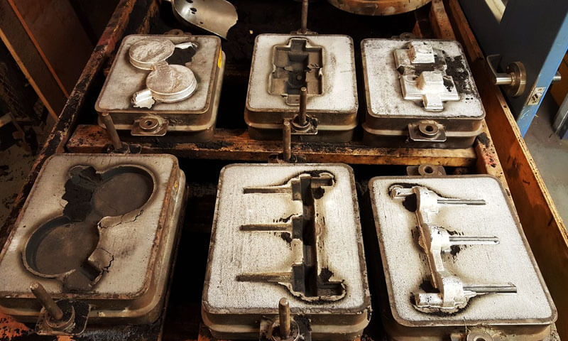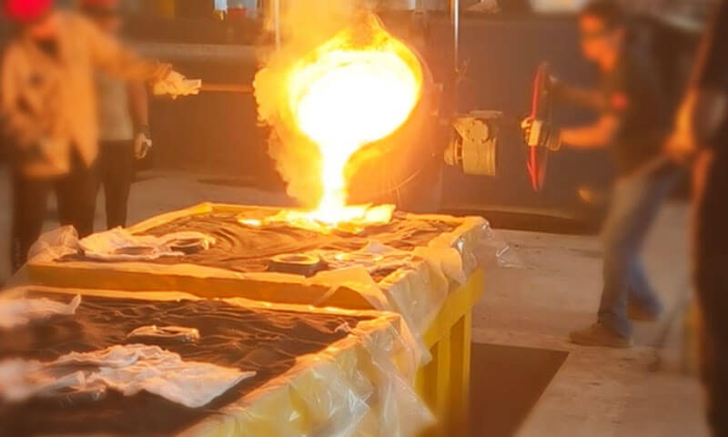
The lost foam shell process is an interesting hybrid. It combines the pattern elimination mechanism of lost foam casting with the refractory shell of investment casting.
Teoretski, this gives you the geometric freedom of lost foam plus the high-temperature refractory performance of a ceramic shell—which should mean excellent surface quality on stainless steel parts.
U praksi, burn-on remains one of the most persistent defects I deal with on stainless steel lost foam shell work. And the reason is not hard to understand.
Nehrđajući čelik has more alloying elements, pours at a higher temperature, flows more aggressively, and oxidizes more readily than carbon steel or cast iron. Every one of those characteristics makes the shell more vulnerable.
Burn-on comes in three forms—mechanical, kemijski, and thermal—and in real production they rarely appear alone. A single casting may show all three at different locations.
This article breaks the problem down across six dimensions: the shell refractory system, the shell-building process, the foam pattern, sustav zatvaranja, the molten steel, and the pouring process.
1. Understanding Sand Burn-On in Stainless Steel Lost Foam Shell Casting
Before adjusting process parameters, it is important to distinguish the different forms of sand burn-on.
Although they may appear similar after shakeout, their formation mechanisms and corrective measures are different.
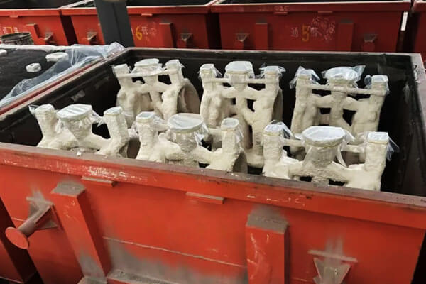
Mechanical Penetration
Mechanical penetration occurs when molten steel enters the pores, gaps, or cracks of the ceramic shell and solidifies around the refractory particles.
It is primarily associated with insufficient shell density, excessive permeability, inadequate coating strength, or unfavorable pressure conditions during pouring.
Tipične karakteristike uključuju:
- Refractory particles firmly embedded in the casting surface.
- Hrapav, irregular surface areas with a granular appearance.
- Localized penetration around thin shell sections, pukotine, or weak coating areas.
- Difficult cleaning when molten steel penetrates deeply into the shell structure.
Mechanical penetration is often aggravated by excessive vacuum pressure, coarse refractory particles, insufficient facecoat thickness, and high molten-metal velocity.
Chemical Burn-On
Chemical burn-on results from reactions between molten steel and the refractory materials at the mold-metal interface. Stainless steel contains significant amounts of chromium, nikla, i drugi legirajući elementi.
Pri visokim temperaturama, oxidation and interfacial reactions can produce complex oxides and low-melting reaction products that bond strongly to the casting surface.
Tipične karakteristike uključuju:
- Gusta, strongly bonded refractory layer.
- Glassy or partially fused material adhering to the casting.
- Discoloration or a chemically reacted surface beneath the adhering sand.
- High cleaning difficulty, often requiring aggressive grinding or specialized surface treatment.
Chemical burn-on is particularly difficult to remove because the refractory material is no longer simply attached mechanically; it has reacted with the molten steel or its oxide products.
Thermal Adhesion
Thermal adhesion develops when the ceramic shell surface softens, sinters, or loses structural stability under prolonged exposure to high temperatures.
The refractory particles may partially fuse together and adhere to the casting surface.
This mechanism is associated with inadequate refractory selection, excessive pouring temperature, prolonged metal-shell contact, and local hot spots.
U praktičnoj proizvodnji, thermal adhesion often occurs together with chemical burn-on, especially around thick sections and hot spots where solidification is delayed.
2. Refractory Shell System: The First Line of Defense Against Burn-On
The refractory shell is the primary barrier between molten stainless steel and the surrounding mold materials.
Its high-temperature strength, kemijska stabilnost, particle distribution, and permeability directly affect the risk of burn-on.
For stainless steel lost foam shell casting, refractory selection should be based not only on nominal refractoriness but also on chemical compatibility with the alloy, resistance to metal penetration, and stability under the actual pouring conditions.
Select Facecoat Refractories with Sufficient Refractoriness
The facecoat directly contacts molten steel, so its performance largely determines the casting surface quality.
For common 304 i 316 odljevi od nehrđajućeg čelika, pouring temperatures generally range from 1,580–1,650°C, while some high-alloy stainless steels require even higher temperatures.
Pod tim uvjetima, ordinary quartz-based facecoat materials are generally unsuitable.
Quartz undergoes crystalline transformations at elevated temperatures and can soften or react under severe casting conditions.
When molten stainless steel directly contacts a quartz-rich facecoat, the shell surface may lose stability, allowing metal penetration and interfacial reactions.
More suitable facecoat materials include:
- High-purity zircon flour: Offers good refractoriness and resistance to molten-metal penetration. It is widely used for demanding steel casting applications.
- Electrofused mullite: Provides good high-temperature stability and can be used in facecoat formulations where its chemical compatibility and thermal properties are appropriate.
- Specialized refractory blends: Zircon-mullite or other engineered systems can be selected according to the stainless steel grade, geometrija lijevanja, and pouring temperature.
The key is to select a refractory system that maintains its structure and resists chemical attack throughout the actual metal-shell contact period.
Simply increasing the nominal refractory content does not guarantee better performance if the material contains excessive impurities or has an unsuitable particle-size distribution.
Control Refractory Purity
The purity of zircon flour, mullite powder, and other facecoat materials is critical.
Impurities such as iron oxide, alkali metal oxides, and calcium- or magnesium-bearing compounds can lower the effective softening temperature of the refractory system.
Pri visokim temperaturama, these impurities may participate in interfacial reactions with oxides and alloying elements in the molten steel.
Depending on the local chemical conditions, they can form lower-melting silicate phases or glassy reaction products.
These products weaken the shell surface and make refractory adhesion more difficult to remove.
Iz tog razloga, foundries should establish incoming-material specifications for:
- Chemical composition and impurity levels.
- Refractory particle-size distribution.
- Moisture content and storage condition.
- Batch consistency and compatibility with the selected binder.
A high-purity refractory is particularly important for complex stainless steel castings with thick sections, where the shell remains exposed to high temperatures for an extended period.
Match the Binder System to the Refractory
The binder determines how effectively refractory particles bond together and how densely the facecoat develops.
For stainless steel lost foam shell casting, silica sol is generally preferable to sodium silicate for demanding facecoat applications.
Sodium silicate introduces alkali components that can reduce the high-temperature stability of the shell and promote the formation of low-melting phases.
Međutim, silica sol must also be properly controlled. Its modulus, sadržaj čvrstih tvari, stabilnost, and compatibility with the refractory powder all affect slurry performance.
An unsuitable silica sol or an imbalanced powder-to-liquid ratio can produce a weak, porozni, or poorly bonded coating.
U proizvodnji, monitor:
- Silica sol modulus and solids content.
- Slurry viscosity and density.
- Powder-to-liquid ratio.
- Slurry stability and sedimentation.
- Coating thickness and drying behavior.
Gusta, uniform facecoat provides better resistance to molten-metal penetration than a coating that contains local thin areas, agglomerates, or interconnected pores.
Design the Backup Shell as a Complete Structure
Although the facecoat provides the primary metal-contact barrier, the backup layers determine the overall strength and dimensional stability of the shell.
If the backup refractory particles are excessively coarse, large interconnected gaps may form between particles or between shell layers.
Molten steel can penetrate these weak regions, particularly when the shell is exposed to high metallostatic pressure.
Thermal expansion mismatch between the facecoat and backup layers can also generate stress during drying, pucajući, i nalijevanje.
If the shell develops cracks, molten steel may enter through them and form linear or sheet-like burn-on.
The shell system should therefore be designed as a compatible multilayer structure. Refractory particle size, debljina sloja, sadržaj veziva, and thermal expansion behavior must be considered together rather than optimized independently.
3. Shell-Making Process: Controlling Coating Density, Sušenje, and Firing
Even high-quality refractory materials cannot prevent burn-on if the shell-making process produces an uneven or insufficiently strong coating.
U proizvodnji, many shell-related defects originate from inconsistent slurry preparation, poor dipping technique, inadequate drying, or improper firing.
Maintain Uniform Facecoat Application
The first coating layer has the greatest influence on surface reproduction and resistance to metal penetration. Its thickness and continuity must be controlled carefully.
Common application problems include:
- Uneven slurry mixing: Refractory powder settles during production, causing local variations in solids content and coating thickness.
- Insufficient coating coverage: Thin areas expose the underlying pattern or leave the facecoat unable to withstand molten-metal contact.
- Air bubbles and coating defects: Trapped bubbles, rupice, and surface depressions create weak points that can become penetration channels.
- Excessive coating buildup: Thick accumulations may dry unevenly, develop internal stresses, or crack during subsequent processing.
Keep the slurry under controlled agitation and monitor its viscosity throughout the coating operation.
During dipping, ensure that the pattern is fully wetted and that excess slurry drains evenly. Air bubbles should be removed before the coating dries.
The objective is not simply to apply more refractory material, but to produce a continuous, kompaktan, and uniformly bonded facecoat.
Ensure Complete Drying Between Shell Layers
Each shell layer must dry sufficiently before the next layer is applied. Visoka vlažnost zraka, inadequate ventilation, and low drying temperatures can leave moisture or residual volatile components inside the coating.
Tijekom izlijevanja, trapped moisture rapidly vaporizes. The resulting gas pressure can cause:
- Facecoat blistering and local lifting.
- Interlayer separation.
- Pucanje školjki.
- Gas channels that allow molten steel to penetrate the refractory structure.
Drying conditions should be adjusted according to the binder system, debljina ljuske, and workshop environment.
Do not determine drying completion solely by the appearance of the outer surface. A coating may feel dry externally while retaining moisture internally.
Stable temperature, vlažnost, and air circulation are essential for repeatable shell quality.
Provide Adequate Shell Thickness and Layer Strength
Stainless steel has a high density, and the metallostatic pressure increases with the height of the molten-metal column.
A shell that is too thin or has insufficient structural strength may deform or crack during pouring.
The total number of facecoat, transition, and backup layers should be determined by casting size, metal head, shell geometry, i uvjeti ulijevanja.
Insufficient shell thickness can allow the shell structure to open under thermal and mechanical loading, increasing the risk of metal penetration.
Međutim, excessive shell thickness is not automatically beneficial. It can increase drying time, toplinski stres, and the risk of uneven shrinkage. The target is sufficient and uniform shell strength, not maximum thickness.
Control Foam Gasification and Shell Firing
Lost foam shell casting differs from conventional investment casting because the foam pattern is gasified rather than removed by traditional steam or hot-water dewaxing.
Firing must therefore provide adequate conditions for removing foam decomposition residues and stabilizing the ceramic shell.
If the firing temperature is too low or the holding time is insufficient, residual carbonaceous material and decomposition products may remain inside the shell.
Tijekom izlijevanja, these residues can generate additional gas and locally affect the shell-metal interface.
Carbonaceous residues may also participate in reactions with the molten steel and its oxide films, depending on the local temperature and oxygen potential.
Rapid heating can create thermal gradients and thermal shock, causing cracks in the shell.
The firing schedule should therefore balance complete residue removal with controlled heating and cooling.
Nakon pucanja, protect the shell from moisture absorption and contamination during cooling, skladištenje, i prijenos.
A fired shell that has absorbed moisture before pouring may no longer provide the same resistance to metal penetration and thermal loading.
4. Foam Pattern Quality and Coating Wettability
The foam pattern determines the geometry of the cavity and provides the surface onto which the ceramic coating is applied.
Poor pattern quality can therefore create facecoat defects before the shell enters the drying and firing stages.
Select Fine and Consistent Foam Beads
EPS bead size and molding quality affect the surface texture and porosity of the foam pattern.
Oversized beads or poorly fused bead structures can leave coarse surface pores and open gaps.
During coating, slurry may penetrate deeply into these openings, reducing the effective facecoat thickness on the pattern surface.
After gasification, the affected shell areas may contain insufficient refractory coverage, allowing molten steel to contact weaker underlying layers.
Use foam beads with a suitable and consistent particle size, and maintain stable pattern molding conditions.
The pattern should have a uniform surface without excessive open pores, bead separation, or local defects.
Remove Oil and Release-Agent Residues
Oil contamination and residual release agents can significantly reduce coating wettability.
When the slurry cannot spread uniformly over the foam surface, it may retract and form local shrinkage holes, bare areas, or peeling regions.
These discontinuities expose the underlying shell structure and create direct paths for molten-metal penetration.
Before coating, inspect the foam pattern for oil, prah, release-agent residues, i ostali onečišćenja. Pattern cleaning and handling procedures should prevent recontamination after preparation.
Improve Surface Geometry at Sharp Corners
Oštri uglovi, tanka rebra, and narrow transitions are difficult areas for uniform coating application.
Slurry may drain away from these locations, leaving a thinner refractory layer than on broad surfaces.
These regions can also experience severe thermal loading during filling, particularly when molten steel impinges directly on them or remains in contact with the shell for an extended period.
Where casting design permits, use appropriate corner radii and smooth transitions. During coating, pay particular attention to thin ribs, unutarnji kutovi, and other geometrically difficult areas.
Local coating reinforcement may be necessary where the shell is exposed to concentrated thermal or mechanical loading.
5. Molten Steel Chemistry and Melting: Controlling Chemical Burn-On
Molten steel chemistry is a major factor in chemical burn-on, and it is often overlooked when foundries focus primarily on refractory materials and shell preparation.
U usporedbi s ugljičnim čelikom, stainless steel contains higher levels of alloying elements, particularly chromium and nickel, which influence oxidation behavior and metal-refractory interactions at high temperatures.
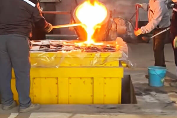
Deoxidation and Oxygen Control
Poor deoxidation can leave excessive dissolved oxygen in the molten steel, increasing oxidation reactions during pouring.
These reactions generate metal oxides that can interact with the ceramic facecoat, weakening its surface and promoting interfacial adhesion.
Kromov oksid (Cr₂o₃) is one of the important oxidation products in stainless steel casting.
Although Cr₂O₃ itself has a high melting point, it can react with other oxides, including silica-bearing impurities in the refractory system, to form complex reaction products.
Depending on their composition, these products may have lower melting temperatures and form a strongly bonded layer between the casting and shell.
Da bi se ovaj rizik smanjio, foundries should maintain effective deoxidation practices, minimize secondary oxidation during transfer and pouring, and remove slag and oxide inclusions thoroughly before casting.
Effects of Alloying Elements
The alloy composition influences the chemical reactions occurring at the steel-shell interface.
- Krom: Chromium has a strong affinity for oxygen and readily forms chromium-rich oxides at high temperatures.
These oxides may interact with SiO₂ in the refractory system, contributing to complex silicate reaction products and chemical adhesion. - Sulfur and phosphorus: Excessive sulfur and phosphorus can complicate melt quality and interfacial behavior.
Sulfur may contribute to sulfide formation, while both elements should be controlled within the specified limits for the stainless steel grade.
Their effects should be evaluated alongside the actual oxide and inclusion chemistry rather than treated as the sole causes of burn-on.
Strict chemical composition control, combined with effective slag removal and melt cleanliness management, helps reduce the risk of refractory-metal reactions.
Avoid Excessive Pouring Temperature
Pouring temperature is another critical factor. When molten steel exceeds the upper process limit, excessive superheat increases the thermal load on the ceramic shell and extends the period of high-temperature interaction between the metal and refractory.
The resulting conditions can accelerate facecoat erosion, promote chemical reactions, and increase molten-metal penetration into shell pores or weak areas.
Even a properly prepared shell may suffer severe burn-on if it remains in contact with excessively hot steel for too long.
For common 304 i 316 odljevi od nehrđajućeg čelika, the typical pouring temperature range is 1,580–1,650°C, although the actual target should be determined by alloy grade, geometrija lijevanja, debljina presjeka, and filling requirements.
Foundries should avoid using excessive superheat to compensate for inadequate gating or poor shell preparation.
6. Gating System and Vacuum Control: Preventing Metal Penetration and Shell Erosion
Lost foam shell casting often uses a vacuum system to support pattern gasification and mold filling.
This makes pressure management an important process variable in addition to conventional gating design.
Vacuum does not automatically improve casting quality. Its effect depends on shell permeability, mold configuration, metal head, proizvodnja plina, and the timing and distribution of pressure application.
Avoid Excessive or Uneven Vacuum Pressure
Excessive vacuum may increase the pressure difference across the shell and promote molten-metal penetration into connected pores or weak areas, particularly when the shell has inadequate density or cracks.
Uneven vacuum distribution can also produce localized differences in pressure conditions, making defects more likely in certain casting regions.
The appropriate vacuum level should be established through production trials rather than applying the maximum available suction.
Pay particular attention to:
- Vacuum pressure and its stability during pouring.
- Pressure distribution around thick and thin casting sections.
- Shell permeability and structural integrity.
- The relationship between vacuum level and molten-metal head.
Where burn-on repeatedly occurs in thick sections or hot spots, compare local defect distribution with the vacuum system’s pressure distribution before changing the refractory formulation.
Control the Timing and Stages of Vacuum Application
Vacuum application should be coordinated with shell condition and the pouring sequence.
Applying vacuum before the shell has reached the required condition may disturb the coating or increase the risk of shell damage.
Maintaining an unnecessarily high vacuum throughout pouring and early solidification may also increase metal penetration under certain process configurations.
A staged vacuum schedule can be evaluated:
- Establish the required vacuum condition before pouring, according to the equipment and shell system.
- Maintain a controlled level during initial filling to support stable gas evacuation.
- Reassess the vacuum level as the metal fills and begins to solidify, reducing it where the process design permits and trials show a benefit.
The exact timing and pressure values are equipment- and process-specific. They should be validated using pressure records, casting inspection, and repeatable production trials.
Optimize Gating to Reduce Direct Shell Impingement
A poorly designed gating system can cause localized shell erosion even when the refractory materials and shell-making process are satisfactory.
If an ingate directs high-velocity molten steel straight toward the shell wall, the impact can remove or damage the facecoat.
Refractory particles may then become entrained in the metal, while the exposed shell structure becomes more vulnerable to penetration and burn-on.
A well-designed gating system should:
- Avoid direct impingement of the incoming metal on vulnerable shell surfaces.
- Provide smooth and controlled filling.
- Minimize turbulence and oxide-film entrainment.
- Distribute molten steel without creating concentrated thermal loads.
- Reduce prolonged exposure of local shell areas to high-temperature metal.
The gate position and cross-sectional area should be selected according to casting geometry, vrijeme punjenja, and alloy characteristics.
Simply increasing pouring speed to shorten filling time may worsen shell erosion and oxide entrainment.
Manage Hot Spots and Feeding Design
Thick sections and poorly designed hot spots remain vulnerable to burn-on because they cool more slowly than surrounding areas.
Molten steel stays in contact with the shell for longer, increasing the duration of thermal and chemical exposure.
If burn-on repeatedly appears around thick sections and is accompanied by shrinkage porosity, review both the feeding system and local thermal conditions.
Possible improvements include:
- Adjusting riser position and size.
- Reducing unnecessary local metal accumulation.
- Improving section transitions where casting design permits.
- Applying a locally reinforced, erosion-resistant facecoat in areas exposed to severe thermal loading.
Increasing local coating thickness can help in selected areas, but it should not replace correction of an unsuitable gating or feeding design.
7. Other Production Factors That Can Contribute to Burn-On
Not all burn-on defects originate during shell preparation or pouring. Skladištenje, coating management, and external filling materials can also affect the final casting surface.
Protect Fired Shells During Storage and Transfer
Fired ceramic shells should be stored in a clean, dry environment. Prah, loose refractory particles, and workshop contaminants deposited on the facecoat may become attached to the casting during pouring.
Moisture absorption is another concern. A shell that has been properly fired but then exposed to humid conditions may lose some of its process stability.
Establish suitable storage and transfer procedures, and inspect shells before pouring.
Monitor Facecoat Slurry Aging
Facecoat slurry can deteriorate during extended storage or repeated use. Refractory powder may settle, binder stability may change, and agglomerates may develop.
These changes affect viscosity, Ujednačenost premaza, and bonding strength.
An aged or unstable slurry can produce weak coating areas that are more susceptible to cracking, piling, and metal penetration.
Use defined slurry control procedures, including regular mixing, viscosity checks, and replacement or reconditioning according to established production limits.
Do not rely on visual appearance alone to determine whether a slurry remains suitable for use.
Control External Filling Sand
The sand surrounding the ceramic shell provides support during pouring. Its quality becomes particularly important if the shell cracks or loses integrity.
Excessive fines, low-refractoriness particles, or contaminated filling sand can create additional inclusions when they enter the cavity through a damaged shell.
Use clean, suitable filling sand and maintain stable filling and compaction procedures to avoid unnecessary mechanical loading on the shell.
8. Practical Prevention Strategy: Building a Stable Burn-On Control System
The following is the consolidated prevention framework I use on stainless steel lost foam shell projects.
Refractory System
Koristiti high-purity zircon flour or electrofused mullite combined with high-modulus silica sol for the facecoat.
Avoid quartz-based facecoats for stainless steel casting. Control refractory impurities and regularly check the slurry powder-to-liquid ratio, viskoznost, i stabilnost.
Građevina
Establish strict interlayer drying procedures. Each coating layer must dry completely before the next layer is applied.
Maintain stable temperature and humidity in the shell-making area, and ensure sufficient firing to remove foam decomposition residues.
Protect fired shells from moisture absorption during cooling, skladištenje, i prijevoz.
Foam Pattern Quality
Use fine and consistent foam beads to obtain a uniform pattern surface. Thoroughly remove release-agent residues and ensure that the refractory coating wets and covers the pattern continuously.
Where casting geometry permits, use suitable radii at sharp corners and transitions to improve coating coverage.
Tope i izlijevanje
Apply effective deoxidation practices and control oxygen levels in the molten steel.
Maintain pouring temperature within the appropriate range for the alloy and casting geometry, avoiding excessive superheat. Keep sulfur and phosphorus within the specified composition limits.
Vacuum and Gating Control
Adopt a staged vacuum-control strategy. Maintain moderate vacuum during initial pouring and reduce it after the steel begins to form a solidified skin, where process trials confirm this is beneficial.
Position ingates to avoid direct impingement on shell walls, and control the filling rate to minimize turbulence and refractory erosion.
Hot-Spot Protection
Pay particular attention to thick sections and local hot spots, where prolonged high-temperature contact increases the risk of shell erosion and burn-on.
Gdje je potrebno, increase facecoat thickness locally or use an erosion-resistant refractory formulation suited to the actual casting conditions.
9. Zaključak
Sand burn-on in stainless steel lost foam shell casting is the result of interactions between refractory stability, kvaliteta ljuske, molten steel chemistry, i uvjeti ulijevanja.
Mechanical penetration is commonly associated with shell porosity, weak coating areas, and unfavorable pressure conditions.
Chemical burn-on is more closely related to interfacial reactions between molten steel, oksidi, and refractory impurities, while thermal adhesion is associated with shell softening, sintering, and prolonged high-temperature exposure.
U stvarnoj proizvodnji, these mechanisms frequently overlap.
For foundries producing complex 304, 316, and high-alloy stainless steel components, process stability is more important than isolated parameter adjustments.
The objective is to prevent molten steel from penetrating, reacting with, or excessively heating the ceramic shell in the first place.
By controlling the complete casting process and validating improvements through production trials, manufacturers can reduce burn-on, simplify cleaning, poboljšati kvalitetu površine, and achieve more consistent stainless steel castings.
Česta pitanja
Why is quartz unsuitable for a stainless steel facecoat?
Quartz transforms crystallographically and begins to soften and melt above 1,470°C.
Stainless steel is poured at 1,580–1,650°C, so the quartz facecoat is directly wetted by liquid steel and chemical burn-on results. Use zircon or fused mullite instead.
Why does incomplete interlayer drying cause burn-on?
Residual moisture vaporizes violently at pouring, blistering and cracking the shell and creating gas channels.
Liquid steel penetrates those channels, producing burn-on and often gas porosity at the same time.
How does foam pattern quality affect burn-on?
Oversized foam beads create large surface pores that absorb slurry and thin the facecoat, leaving bare areas after gasification.
Residual release agent causes poor wetting and bare patches. Sharp corners receive thin coating and stay hot longer.
Why does steel oxygen content matter for burn-on?
High free oxygen reduces the refractory at pouring temperature, softening the shell surface.
It also forms Cr₂O₃ and other low-melting oxides that react with the shell to form a tenacious glassy phase.