Tietokoneavusteinen suunnittelu (Cad) on mullistanut tuotteiden suunnittelun, kehitetty, analysoitu, ja valmistettu.
Viihdeelektroniikasta ja lääketieteellisistä laitteista lentokoneisiin, autot, ja teollisuuskoneet, Lähes jokainen moderni tuote alkaa digitaalisesta CAD-mallista.
Enemmän kuin pelkkä paperipiirustusten korvaaminen, CAD:sta on tullut nykyaikaisen suunnittelun digitaalinen perusta.
Yksi CAD-malli voi tukea visualisointia, rakenteellinen simulointi, valmistuksen suunnittelu, kustannusarvio, laaduntarkastus, ja jopa tuotteen elinkaaren hallinta (PLM).
Kuten Teollisuus 4.0, digitaaliset kaksoset, tekoäly (AI), ja lisäaineiden valmistus kehittyy edelleen, CAD:sta on tulossa yhä älykkäämpi ja yhdistetympi koko valmistusekosysteemissä.
1. Mitä on tietokoneavusteinen suunnittelu (Cad)?
Tietokoneavusteinen suunnittelu (Cad) on tietokoneohjelmiston käyttö luomiseen, muuttaa, analysoida, optimoida, ja dokumentoida fyysisten tuotteiden tai teknisten järjestelmien suunnittelu.
Toisin kuin perinteinen piirustus, CAD:n avulla suunnittelijat voivat rakentaa tarkkoja digitaalisia malleja, jotka edustavat tarkasti tuotteen geometriaa, mitat, materiaalit, toleranssit, ja toiminnalliset ominaisuudet.
Nämä digitaaliset mallit toimivat luotettavana suunnittelutiedon lähteenä koko tuotekehitysprosessin ajan.
Tietokoneavusteista suunnittelua käyttävät useiden alojen ammattilaiset, mukaan lukien:
- Konetekniikka
- Teollinen muotoilu
- Arkkitehtuuri
- Maa- ja vesirakentaminen
- Ilmailu- ja avaruustekniikka
- Autotekniikka
- Sähkötekniikka
- Lääketieteellisten laitteiden kehitys
- Kuluttajatuotteiden suunnittelu
Tietokoneavusteisen suunnittelun ydintoiminnot
Nykyaikaiset CAD-järjestelmät ulottuvat paljon yksinkertaista piirtämistä pidemmälle. Ne tarjoavat integroidun alustan, joka tukee koko suunnitteluprosessia.
Ensisijaisia ominaisuuksia ovat mm:
- Kaksiulotteinen piirustus
- Kolmiulotteinen solid-mallinnus
- Pintamallinnus
- Kokoonpanosuunnittelu
- Parametrinen mallinnus
- Mitoitus ja toleranssi
- Teknisten piirustusten sukupolvi
- Liikesimulaatio
- Äärellisen elementin analyysi (Fea) integraatio
- Valmistustietojen valmistelu
- Tuotteen visualisointi
- Suunnitteluyhteistyö
- Tuotteen elinkaaren integrointi
2. Tietokoneavusteisen suunnittelun kehitys
Tietokoneavusteisen suunnittelun historia heijastaa digitaalisen suunnittelun laajempaa kehitystä.
Manuaalisen piirtämisen aikakausi
Ennen kuin tietokoneet tulivat laajalti saataville, tekniset piirustukset tehtiin kokonaan käsin.
Suunnittelutarkistukset vaativat usein kokonaisten arkkien uudelleenpiirtämistä, tekee tuotekehityksestä hidasta ja kallista.
Varhainen tietokonegrafiikka (1960s)
Yksi varhaisimmista virstanpylväistä oli Luonnoslehtiö, kehitti Ivan Sutherland vuonna 1963.
Sketchpad esitteli interaktiivisen tietokonegrafiikan, geometriset rajoitukset, ja oliopohjainen mallinnus, luo perustan nykyaikaisille CAD-järjestelmille.
Kaupalliset tietokoneavusteiset suunnittelujärjestelmät (1970s–1980-luku)
Kun laskentateho kasvoi, kaupallisia CAD-ohjelmistoja syntyi sellaisille aloille kuin ilmailu- ja autoteollisuus.
Nämä varhaiset järjestelmät paransivat dramaattisesti luonnoksen tehokkuutta, mutta pysyivät kalliina ja vain suurten yritysten saatavilla.
Parametrisen mallinnuksen vallankumous (1990s)
Parametrisen solid-mallinnuksen käyttöönotto muutti tuotesuunnittelun.
Yksittäisten piirustuselementtien muokkaamisen sijaan, suunnittelijat voivat määritellä ominaisuuksien välisiä suhteita, mahdollistaa mallien päivittämisen automaattisesti aina, kun mitat tai parametrit muuttuvat.
Tämä innovaatio paransi merkittävästi suunnittelun tuottavuutta ja suunnittelun johdonmukaisuutta.
Pilvi- ja tekoälypohjainen CAD (Tänään)
Nykyaikaiset tietokoneavusteisen suunnittelun alustat integroituvat yhä enemmän:
- Pilviyhteistyö
- Tekoäly
- Generatiivinen suunnittelu
- Simulointi
- Digitaaliset kaksoset
- Valmistusautomaatio
Nykypäivän CAD-järjestelmät ovat kehittyneet kattaviksi suunnittelualustoiksi itsenäisten piirustustyökalujen sijaan.
3. Miten tietokoneavusteinen suunnittelu toimii
Tietokoneavusteinen suunnittelu (Cad) on paljon enemmän kuin digitaalinen piirustustyökalu.
Se on integroitu suunnittelualusta, joka muuntaa suunnittelukonseptit älykkäiksi digitaalisiksi malleiksi, jotka pystyvät tukemaan koko tuotekehitysprosessia – konseptisuunnittelusta ja suunnitteluanalyysistä valmistukseen., tarkastus, ja tuotteen elinkaaren hallinta.
Suunnittelukonseptista digitaaliseen malliin
Jokainen tietokoneavusteinen suunnitteluprojekti alkaa suunnittelutavoitteesta.
Insinöörit määrittelevät ensin tuotteen toiminnalliset vaatimukset, käyttöolosuhteet, materiaalivalinta, valmistusprosessi, ja suorituskykytavoitteet.
Nämä suunnittelusyötteet määrittävät komponentin yleisen geometrian ja rakenteellisen konfiguraation.
Mallinnusprosessi alkaa tyypillisesti kaksiulotteisella luonnoksella, joka on luotu referenssitasolle. Toisin kuin perinteiset piirustukset, CAD-luonnos ei ole pelkkä kokoelma viivoja.
Sen sijaan, se on täysin rajoitettu geometrinen kehys, jossa mitat, kulmat, säteet, kosketusolosuhteet, symmetria, ja sijaintisuhteet määritellään matemaattisesti.
Kun luonnos on täysin rajoitettu, se toimii perustana kolmiulotteisen geometrian luomiselle operaatioilla, kuten suulakepuristamalla, vallankumous, lakaistaan, lofting, tai rajapinnan luominen.
Nämä ominaisuudet rakentavat vähitellen täydellisen digitaalisen esityksen tuotteesta säilyttäen samalla tarkat mittasuhteet.
Koska jokainen ominaisuus liittyy taustalla oleviin suunnitteluparametreihin, muutokset voidaan tehdä nopeasti ilman koko mallin uudelleenrakentamista.
Parametrinen mallinnus ja suunnittelun tarkoitus
Yksi nykyaikaisen CAD-ohjelmiston tehokkaimmista ominaisuuksista on parametrinen mallinnus, jonka avulla insinöörit voivat määritellä tuotteita suunnittelusuhteiden perusteella kiinteän geometrian sijaan.
Parametrisessa mallissa, ulottuvuuksia käsitellään muokattavina muuttujina. Ominaisuudet on linkitetty toisiinsa rajoituksilla, jotka kuvastavat suunniteltua suunnittelulogiikkaa.
Kun yksi ulottuvuus muuttuu, kaikki riippuvat ominaisuudet päivittyvät automaattisesti säilyttäen samalla alkuperäisen suunnittelutarkoituksen.
Esimerkiksi, akselin halkaisijan lisääminen voi automaattisesti säätää liitosreikien kokoa, kantapaikat, keilat, ja niihin liittyvät kokoonpanot ilman, että jokaista yksittäistä ominaisuutta tarvitsee muuttaa manuaalisesti.
Tämä lähestymistapa tarjoaa useita tärkeitä etuja:
- Nopea suunnittelun iteraatio
- Vähemmän mallinnusvirheitä
- Parempi suunnittelun johdonmukaisuus
- Helpompi tuotteiden räätälöinti
- Tehokas tuoteperheiden luominen
Parametrinen mallinnus on erityisen arvokasta aloilla, joilla tuotteita on useita kokoja tai kokoonpanoja, Valmistajat voivat luoda uusia muunnelmia muuttamalla vain pientä määrää avainparametreja.
Ominaisuuspohjainen solid-mallinnus
Sen sijaan, että rakentaisit monimutkaisia muotoja yhdeksi objektiksi, moderni tietokoneavusteinen suunnitteluohjelmisto rakentaa malleja käyttämällä useita suunnitteluominaisuuksia.
Jokainen ominaisuus edustaa valmistusta tai toiminnallista toimintaa, kuten pomon lisääminen, reiän luominen, taskun leikkaaminen, fileen levittäminen, tai muodostaa kylkiluita.
Nämä ominaisuudet on järjestetty ominaisuushistoriapuuhun, joka tallentaa koko mallinnusprosessin.
Tämän historiaan perustuvan lähestymistavan avulla insinöörit voivat palata mihin tahansa suunnitteluvaiheeseen ja muokata aikaisempia ominaisuuksia luomatta koko mallia uudelleen.
Koska seuraavat ominaisuudet uusiutuvat automaattisesti, suunnitteluversioista tulee huomattavasti nopeampia ja luotettavampia.
Ominaisuuspohjainen mallinnus heijastaa myös todellisia valmistusprosesseja, tuotantoinsinöörien on helpompi ymmärtää, miten komponentit valmistetaan.
Kokoonpanomallinnus ja liikkeen simulointi
Useimmat suunnittelutuotteet koostuvat useista toisiinsa yhdistetyistä osista yksittäisten osien sijaan.
Tietokoneavusteinen suunnitteluohjelmisto tarjoaa siksi kattavat kokoonpanomallinnusominaisuudet, joiden avulla suunnittelijat voivat yhdistää yksittäisiä komponentteja kokonaisiksi mekaanisiksi järjestelmiksi..
Kokoonpanon luomisen aikana, insinöörit määrittelevät geometriset suhteet, kuten samankeskisyyden, sattuma, linjaus, kompensaatioita, ja kiertorajoitukset.
Nämä suhteet varmistavat, että komponentit on sijoitettu oikein ja toimivat yhdessä tarkoitetulla tavalla.
Nykyaikaiset CAD-alustat tukevat myös liikesimulaatiota, antaa insinööreille mahdollisuuden arvioida kokoonpanojen käyttäytymistä käyttöolosuhteissa ennen fyysisten prototyyppien tuotantoa.
Liikeanalyysi voi tunnistaa:
- Mekaaninen häiriö
- Törmäys liikkuvien osien välillä
- Liikealueen rajoitukset
- Kokoonpanon järjestysongelmat
- Kinemaattinen suorituskyky
Havaitsemalla nämä ongelmat digitaalisessa suunnitteluvaiheessa, valmistajat voivat välttää kalliita muutoksia myöhemmin tuotannossa.
Tekninen analyysi ja suunnittelun tarkastus
CAD-malli on paljon enemmän kuin visuaalinen esitys – se toimii myös teknisen analyysin perustana.
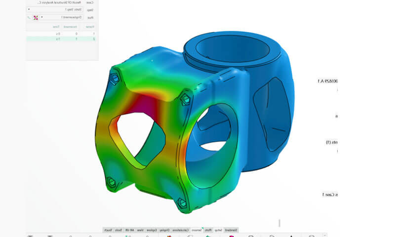
Monet nykyaikaiset CAD-alustat integroivat tietokoneavusteisen suunnittelun (CAE) työkaluja, joiden avulla suunnittelijat voivat arvioida tuotteen suorituskykyä ennen valmistuksen aloittamista.
Sen sijaan, että luottaisi vain fyysiseen testaukseen, insinöörit voivat simuloida todellisia toimintaolosuhteita digitaalisessa ympäristössä.
Yleisiin analyyseihin kuuluu rakenteellinen jännitys, muodonmuutos, värähtely, lämmön jakautuminen, nestevirtaus, väsymyselämä, ja nurjahduskäyttäytyminen.
Näiden simulaatioiden avulla insinöörit voivat optimoida suunnitelmat tunnistamalla heikkoja alueita, vähentää turhaa materiaalia, turvatekijöiden parantaminen, ja tuotteiden luotettavuuden parantaminen minimoimalla kalliiden prototyyppitestausten tarpeen.
Valmistettavuuden suunnittelu (Dfm)
Tehokas tietokoneavusteinen suunnittelumallinnus ulottuu tuotteen toiminnallisuutta pidemmälle – siinä otetaan huomioon myös, miten komponentti valmistetaan.
Nykyaikaiset CAD-järjestelmät tukevat Design for Manufacturability (Dfm) auttamalla insinöörejä arvioimaan, voidaanko suunnittelu tuottaa tehokkaasti käyttämällä prosesseja, kuten CNC-työstöä, investointi, ruiskuvalu, metallilevyjen valmistus, tai lisäaineiden valmistus.
Esimerkiksi, CAD-ohjelmiston avulla suunnittelijat voivat arvioida valettujen komponenttien vetokulmat, seinämän vähimmäispaksuus valukappaleille, koneistuksen saavutettavuus, reikien syvyydet, kulman säteet, ja työstötyökalujen välykset.
Ottamalla valmistusnäkökohdat huomioon suunnitteluvaiheessa, yritykset voivat vähentää tuotantokustannuksia merkittävästi, minimoida suunnittelumuutokset, ja parantaa tuotteiden laatua.
4. Tietokoneavusteisten suunnitteluohjelmistojen tyypit
Tietokoneavusteinen suunnitteluohjelmisto on kehittynyt monipuoliseksi ekosysteemiksi, joka on räätälöity eri tekniikan aloille, teollisuus, ja tuotekehityksen vaiheet.
Kaikilla CAD-järjestelmillä on yhteinen tavoite luoda tarkkoja digitaalisia malleja, ne eroavat huomattavasti mallinnusfilosofiastaan, laskentaominaisuudet, yhteistyöominaisuudet, ja integrointi valmistus- ja simulointityökaluihin.
2D Tietokoneavusteisen suunnittelun laatiminen
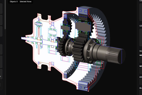
Kaksiulotteinen CAD-ohjelmisto keskittyy viivoista koostuvien suunnittelupiirustusten luomiseen, kaaria, mitat, symboleja, ja huomautuksia.
Vaikka nykyaikainen suunnittelu luottaa yhä enemmän kolmiulotteiseen mallinnukseen, 2D-piirustus on edelleen välttämätön valmistusdokumentaatiossa, kasvien asettelut, putkistokaaviot, sähkökaaviot, ja vanhat piirustusversiot.
Verrattuna manuaaliseen piirtämiseen, 2D CAD parantaa merkittävästi piirustuksen tarkkuutta, tarkistusnopeus, ja dokumenttien hallinta.
Kerrokset, uudelleenkäytettävät lohkot, mittatyylejä, ja automaattinen skaalaus yksinkertaistavat standardisoitujen teknisten piirustusten laatimista huomattavasti.
Tyypilliset sovellukset sisältävät:
- Valmistuspiirustukset
- Arkkitehtoniset pohjapiirrokset
- Rakenteelliset asettelut
- Sähkökytkentäkaaviot
- Hydrauliset ja pneumaattiset kaaviot
- Prosessin vuokaaviot (PFD)
- Putkisto- ja instrumentointikaaviot (P&ID)
Tämän kategorian tunnetuin ohjelmisto on AutoCAD, joka on pysynyt alan standardina vuosikymmeniä.
3D Parametrinen tietokoneavusteinen suunnittelu
Parametrinen mallinnus edustaa vallitsevaa lähestymistapaa nykyaikaisessa koneenrakennuksessa.
Toisin kuin staattinen geometrinen mallinnus, parametrinen CAD tallentaa jokaisen mallinnusoperaation ja ylläpitää suhteita ominaisuuksien välillä, mitat, ja suunnittelun rajoitukset.
Suunnittelumuutokset etenevät automaattisesti läpi mallin.
Esimerkiksi, asennuslevyn paksuuden lisääminen päivittää automaattisesti reikien syvyydet, kiinnikkeiden pituudet, kokoonpanovälit, massan ominaisuudet, ja niihin liittyvät tekniset piirustukset.
Tämä ominaisuus vähentää dramaattisesti uudelleensuunnitteluun kuluvaa aikaa ja minimoi epäjohdonmukaisuudet tuoteversioiden aikana.
Koska suunnittelutarkoitus on upotettu malliin, parametrinen CAD soveltuu erityisesti tuotteille, joiden suunnittelua optimoidaan usein tai jotka vaativat useita konfiguraatiovaihtoehtoja.
Edustava ohjelmisto sisältää:
| Ohjelmisto | Tyypillisiä toimialoja | Keskeiset vahvuudet |
| SolidWorks | Mekaaniset laitteet, koneet | Käyttäjäystävällinen parametrinen mallinnus |
| Usko | Ilmailu-, autoteollisuus | Kehittyneet suunnitteluominaisuudet |
| Autodesk Inventor | Teollisuuskoneet | Integroitu mekaaninen suunnittelu |
| Solid Edge | Valmistus | Synkroninen ja parametrinen mallinnus |
| CATIA | Ilmailu-, autoteollisuus | Laaja kokoonpanohallinta ja monimutkaiset pinnat |
| Siemens NX | Huippuluokan valmistus | Integroitu CAD, Nokka, ja CAE-alustalla |
Suora mallinnus tietokoneavusteinen suunnittelu
Suora mallinnus poistaa riippuvuuden ominaisuushistoriasta. Mallin luomisen aikana tallennettujen parametrien muokkaamisen sijaan, insinöörit muokkaavat geometriaa suoraan työntämällä, vetämällä, kompensointi, tai kasvojen poistaminen.
Tämä mallinnustapa tarjoaa poikkeuksellista joustavuutta työskennellessäsi tuotujen mallien kanssa, joista puuttuu muokattavia ominaisuuspuita.
Se on erityisen arvokasta konseptisuunnittelun aikana, nopeat tekniset muutokset, käänteinen suunnittelu, ja yhteistyöprojektit, joissa on mukana useita CAD-alustoja.
Vaikka suora mallinnus tarjoaa enemmän vapautta, se yleensä uhraa osan parametristen järjestelmien tarjoamasta automaatiosta ja suunnittelun säilyttämisestä.
Siten, monet nykyaikaiset CAD-alustat yhdistävät molemmat menetelmät, insinöörit voivat valita sopivimman työnkulun tiettyyn tehtävään.
Pintamallinnuksen tietokoneavusteinen suunnittelu
Pintamallinnus on erikoistunut luomaan erittäin monimutkaisia vapaamuotoisia geometrioita, joita ei voida esittää tehokkaasti perinteisillä solid-ominaisuuksilla.
Sen sijaan, että kuvailisit kohteen tilavuutta, pintamallinnus määrittelee sen ulkorajat matemaattisesti jatkuvilla pinnoilla, kuten NURBS (Epätasaiset Rational B-splines).
Suunnittelijat manipuloivat kaarevuutta, jatkuvuus, ja ohjauspisteet poikkeuksellisen tasaisten siirtymien saavuttamiseksi vierekkäisten pintojen välillä.
Tätä tekniikkaa käytetään laajalti, kun aerodynaaminen tehokkuus tai esteettinen ulkonäkö on kriittistä.
Tyypilliset sovellukset sisältävät:
- Autojen ulkopaneelit
- Lentokoneiden rungot
- Kulutuselektroniikka
- Lääketieteelliset implantit
- Teollinen muotoilu
- Kodinkoneet
Koska pienetkin epäjatkuvuudet voivat vaikuttaa sekä ulkonäköön että suorituskykyyn, Kehittyneet pinnan mallinnustyökalut tarjoavat tarkan kaarevuuden jatkuvuuden hallinnan (G0, G1, G2, ja korkeamman tason jatkuvuus).
Vapaamuotoinen ja teollinen suunnittelu tietokoneavusteinen suunnittelu
Teolliset muotoilijat vaativat usein enemmän taiteellista vapautta kuin perinteiset suunnittelu-CAD-järjestelmät tarjoavat.
Vapaamuotoinen mallinnusohjelmisto kattaa taiteellisen luovuuden ja teknisen tarkkuuden välisen kuilun.
Sen sijaan, että luottaisi vain teknisiin mittoihin, Suunnittelijat muotoilevat digitaalista geometriaa osapintojen avulla, ohjaushäkit, ja orgaaniset mallinnustekniikat.
Tuloksena saadut lomakkeet voidaan myöhemmin muuntaa valmistettaviksi suunnittelumalleiksi.
Näitä järjestelmiä käytetään yleisesti kehitettäessä tuotteita, joissa ergonomia ja ulkonäkö ovat ensisijaisia näkökohtia, kuten kulutuselektroniikka, huonekalut, urheilutavarat, ja autojen sisätilat.
Rakennuksen tietomallinnus (BIM)
Vaikka teknisesti eroaa perinteisestä mekaanisesta CAD:sta, Building Information Modeling edustaa CAD-standardia arkkitehtuurin sisällä, tekniikka, ja rakentaminen.
Toisin kuin tavalliset geometriset mallit, BIM-objektit sisältävät laajaa teknistä tietoa, mukaan lukien materiaalispesifikaatiot, rakenteellisia ominaisuuksia, paloluokitukset, huoltoaikataulut, rakentamisen järjestys, ja elinkaarikustannukset.
Rakennusmallin kehittyessä, kaikki siihen liittyvät pohjapiirrokset, nousut, osiot, aikataulut, ja nousujen määrä päivittyvät automaattisesti, parantaa huomattavasti arkkitehtien välistä koordinaatiota, rakennesuunnittelijat, ja rakennusurakoitsijat.
Johtavia BIM-alustoja ovat Autodesk Revit, ArchiCAD, ja Bentley OpenBuildings.
Sähköinen ja elektroninen tietokoneavusteinen suunnittelu (ECAD)
Elektroninen tuotekehitys perustuu erikoistuneisiin CAD-ohjelmistoihin, jotka on optimoitu sähkö- ja elektroniikkasuunnitteluun mekaanisen geometrian sijaan.
ECAD-järjestelmien tuki:
- Kaaviomainen sieppaus
- Painettu piirilevy (Pakkaus) layout
- Signaalin eheysanalyysi
- Komponenttikirjastot
- Reitityksen optimointi
- Valmistusdokumentaatio
Nykyaikaiset elektroniset tuotteet vaativat yhä enemmän yhteistyötä ECAD:n ja mekaanisten CAD-järjestelmien välillä koteloiden yhteensopivuuden varmistamiseksi, liittimen kohdistus, lämmönhallinta, ja sähkömagneettinen suojaus.
Pilvipohjainen tietokoneavusteinen suunnittelu
Pilvilaskenta on muuttanut CAD:n työasemariippuvasta sovelluksesta yhteiskäyttöiseksi suunnittelualustaksi, johon pääsee tavallisten verkkoselaimien kautta.
Suunnittelutiedostojen paikallisen tallentamisen sijaan, pilvipohjaiset järjestelmät ylläpitävät keskitettyjä tietokantoja, jotka tukevat reaaliaikaista yhteistyötä maantieteellisesti hajautettujen suunnittelutiimien välillä.
Insinöörit voivat tarkastella kokoonpanoja samanaikaisesti, toteuttaa suunnittelumuutoksia, seurata tarkistuksia, ja hallita tuotetietoja vaihtamatta useita tiedostoversioita.
Automaattinen versionhallinta vähentää ristiriitaisten muutosten riskiä ja yksinkertaistaa projektinhallintaa.
Cloud CAD on erityisen houkutteleva monikansallisille organisaatioille, startupeista, ja hajautettuja tuotantoverkkoja, koska se alentaa laitteistovaatimuksia ja helpottaa turvallista yhteistyötä eri paikoissa.
5. Tietokoneavusteiset suunnittelutiedostomuodot
Oikean tiedostomuodon valitseminen on kriittinen yhteistyön ja valmistuksen kannalta.
| Tiedostomuoto | Tyypillinen käyttö |
| Askel (.stp, .askel) | Universaali 3D-tiedonvaihto valmistusta varten |
| IGES (.igs) | Pintageometrian vaihto |
| Parasolid (.x_t, .x_b) | Solid mallinnusytimen vaihto |
| STL | 3D-tulostus ja nopea prototyyppien valmistus |
| DWG | 2D luonnostelu |
| DXF | CAD-tiedonvaihto |
| SLDPRT | SOLIDWORKS osatiedosto |
| SLDASM | SOLIDWORKS kokoonpano |
| CATPart | CATIA malli |
| IPT | Autodesk Inventor osa |
Näiden muotojen joukossa, Askel pidetään yleisesti suositumpana vaihtoehtona CNC-työstössä, investointi, ja tarkkuusvalmistus, koska se säilyttää tarkan kiinteän geometrian ja pysyy ohjelmistosta riippumattomana.
6. Missä tietokoneavusteista suunnittelua käytetään modernissa valmistuksessa??
Tietokoneavusteinen suunnittelu (Cad) on tullut nykyaikaisen tuotannon digitaalinen perusta.
Riippumatta siitä, onko tuote valmistettu koneistamalla, valu, muovaus, lisäaineiden valmistus, tai ohutlevyn valmistukseen, lähes jokainen valmistusprosessi alkaa CAD-mallilla.
Se toimii teknisen tiedon ensisijaisena lähteenä, tarjoaa geometrian, mitat, toleranssit, materiaalin tiedot, ja valmistustiedot, joita tarvitaan koko tuotannon elinkaaren ajan.
Tuotesuunnittelu ja suunnittelukehitys
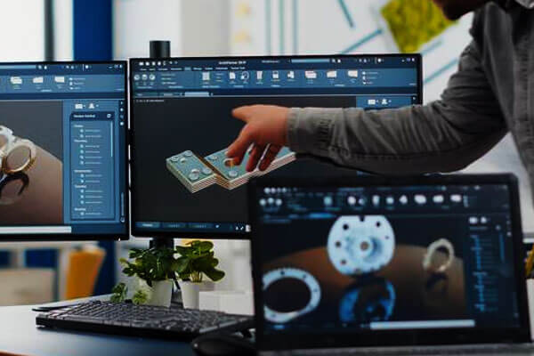
CAD:n varhaisin sovellus on itse tuotesuunnittelu. Insinöörit käyttävät CAD-ohjelmistoa ideoiden muuntamiseen täysin määritellyiksi kolmiulotteisiksi malleiksi, jotka edustavat tarkasti tuotteen geometriaa ja toiminnallisia ominaisuuksia..
Suunnitteluvaiheessa, komponentit luodaan parametrisillä ominaisuuksilla, joita voidaan muokata tehokkaasti tuotevaatimusten kehittyessä.
Suunnittelijat arvioivat mitat, seinämän paksuudet, selvitykset, kokoonpanosuhteet, ja materiaalin jakelu kauan ennen kuin mikään fyysinen prototyyppi on valmistettu.
Tämä digitaalinen lähestymistapa mahdollistaa nopean suunnittelun iteroinnin ja vähentää merkittävästi kehitysaikaa ja suunnittelukustannuksia.
Koska jokainen muutos heijastuu automaattisesti koko malliin, Tekniset muutokset voidaan toteuttaa paljon tehokkaammin kuin perinteiset piirustusmenetelmät.
Uusia tuotteita kehittäville yrityksille, CAD tarjoaa yhteistyöympäristön, jossa teolliset muotoilijat, koneinsinöörit, sähköinsinöörit, ja valmistusasiantuntijat voivat samanaikaisesti osallistua tuotteiden optimointiin.
CNC -koneistus
Tietokoneavusteisella suunnittelulla on keskeinen rooli CNC -koneistus koska jokainen koneistus alkaa tarkasta digitaalisesta mallista.
Kun tietokoneavusteisen suunnittelun malli on valmis, se siirretään CAM-ohjelmistoon, jossa koneistusstrategiat ja työstöradat luodaan automaattisesti.
Ohjelmisto määrittää leikkurin liikkeen, karanopeus, syöttönopeus, leikkaussyvyys, ja komponenttien geometriaan perustuva koneistusjärjestys.
CAD-mallin tarkkuus vaikuttaa suoraan koneistuksen laatuun.
Ominaisuudet, kuten reiät, taskut, fileet, Viisarat, kierteitetyt osat, ja monimutkaiset kaarevat pinnat tulkitaan suoraan mallista, ohjelmointivirheiden minimoiminen ja koneistuksen tehokkuuden parantaminen.
CAD:n avulla insinöörit voivat myös arvioida valmistettavuutta ennen koneistuksen aloittamista.
Ominaisuudet, jotka voivat lisätä koneistuksen vaikeutta, kuten syvät ontelot, terävät sisäkulmat, tai vaikeapääsyisille leikkausalueille, voidaan tunnistaa ja optimoida suunnitteluvaiheessa, alentaa tuotantokustannuksia ja lyhentää toimitusaikoja.
Tarkkuusvalu ja investointivalu
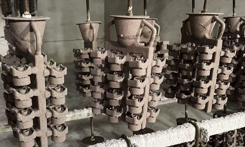
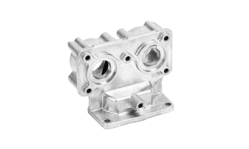
Sijoitusvalu on yksi valmistusprosesseista, joka hyötyy eniten tietokoneavusteisesta suunnittelutekniikasta.
Monimutkainen ruostumaton teräs, alumiini, titaani, ja superseoskomponentit mallinnetaan ensin digitaalisesti ennen kuvioiden ja työkalujen tuottamista.
Koska sijoitusvalu voi toistaa tarkasti monimutkaiset geometriat, CAD:n avulla insinöörit voivat täysin hyödyntää prosessin suunnittelun joustavuutta sisällyttämällä siihen ohuet seinät, sisäiset kohdat, monimutkaiset käyrät, ja integroidut rakenteet yhdeksi valukappaleeksi.
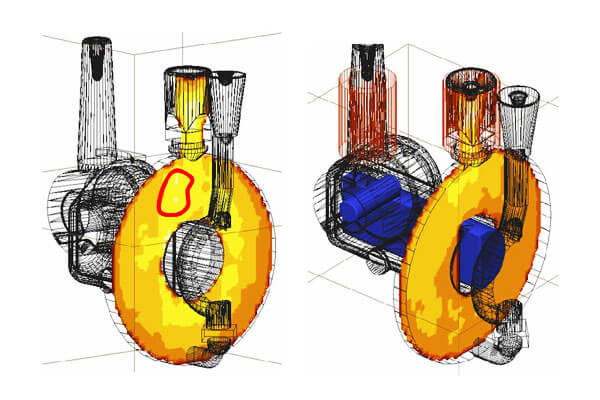
Komponenttien geometrian määrittelyn lisäksi, CAD tukee avainnusjärjestelmien suunnittelua, juoksijat, nousut, ja syöttöratkaisut, jotka vaikuttavat metallin virtaukseen ja jähmettymiskäyttäytymiseen.
Digitaalinen malli toimii pohjana myös valusimulaatioohjelmistolle, joiden avulla insinöörit voivat ennustaa täyttökuvioita, kutistuminen, huokoisuus, ja muut mahdolliset viat ennen tuotannon aloittamista.
Tämä integrointi vähentää merkittävästi työkalujen muutoksia ja parantaa ensikierron valun laatua.
Hiekkavalu ja Lost Foam Casting
Tietokoneavusteinen suunnittelu on muuttanut myös perinteisiä valutekniikoita, kuten hiekkavalua ja vaahtomuovivalua.
Puolesta hiekkavalu, digitaalisia malleja käytetään kuvioiden suunnitteluun, ytimet, ydinlaatikot, ja muovauslaitteet varmistaen samalla asianmukaiset työstövarat, luonnoskulmat, ja kutistumisen kompensointi.
Kadonneessa vaahtomuovivalussa, CAD:n avulla insinöörit voivat luoda erittäin tarkkoja vaahtomuovikuvioita, jotka jäljittelevät komponenttien lopullisen geometrian.
Monimutkaiset kokoonpanot voidaan usein integroida yhdeksi vaahtomuovikuvioksi, vähentää kokoonpanotoimintoja ja parantaa valun yhtenäisyyttä.
CAD-malleihin yhdistetyt simulointityökalut auttavat edelleen optimoimaan muotin täyttöä, kaasun evakuointi, ja jähmettymiskäyttäytyminen, auttaa valimoita minimoimaan valuvirheet ja parantamaan tuotannon tehokkuutta.
Ruiskupuristus ja muovituotekehitys
Muovisessa ruiskuvalu valmistus, Tietokoneavusteinen suunnittelu toimii perustana sekä tuotesuunnittelulle että muottien kehitykselle.
Insinöörit käyttävät CAD-malleja seinämän paksuuden optimointiin, kylkiluiden sijoitus, pomot, snap-fit-ominaisuudet, luonnoskulmat, ja katkaisulinjat ennen työkalujen valmistusta.
Koska muotin rakentaminen on merkittävä investointi, Suunnitteluongelmien varhainen tunnistaminen voi estää kalliita työkalumuutoksia myöhemmin projektin aikana.
Nykyaikaiset CAD-järjestelmät integroivat myös muottivirtaussimuloinnin, jonka avulla suunnittelijat voivat analysoida polymeerin täyttökäyttäytymistä, jäähdytystehokkuus, hitsauslinjat, ilmaluukut, pesuallasmerkit, ja vääntymistä.
Vahvistamalla suunnitelmat digitaalisesti, valmistajat voivat vähentää yrityksen ja erehdyksen määrää muotin käyttöönoton aikana ja samalla parantaa lopputuotteen laatua.
Ohutlevyvalmistus
Ohutlevy valmistus vaatii huolellista materiaalien käyttäytymisen huomioon ottamista taivutus ja muovausoperaatiot.
CAD-ohjelmiston avulla insinöörit voivat suunnitella kolmiulotteisia metallilevykomponentteja samalla kun ne luovat automaattisesti tarkkoja litteitä kuvioita laserleikkausta tai lävistystä varten.
Ohjelmisto ottaa huomioon taivutusvaran, taivutusvähennys, materiaalin paksuus, ja muodostava säde, varmistaa, että valmis komponentti vastaa suunniteltua mallia taivutuksen jälkeen.
Tämä ominaisuus vähentää huomattavasti tuotantovirheitä ja minimoi materiaalihukkaa, erityisesti sellaisilla aloilla kuin autoteollisuus, sähkökotelo, LVI -järjestelmät, ja teollisuuslaitteet.
Additiivinen valmistus ja 3D-tulostus
Lisäaineiden valmistuksen nopea kasvu on entisestään lisännyt tietokoneavusteisen suunnittelun merkitystä.
Toisin kuin subtraktiiviset valmistusprosessit, jotka poistavat materiaalia, 3D tulostus rakentaa komponentteja kerros kerrokselta suoraan digitaalisista malleista.
Jokainen tulostettu komponentti alkaa CAD-tiedostona, joka määrittelee sekä ulkoisen geometrian että yhä kehittyneemmät sisäiset rakenteet.
Nykyaikainen CAD-ohjelmisto tukee edistyneitä suunnittelumenetelmiä, jotka sopivat ainutlaatuisesti lisäainevalmistukseen, mukaan lukien hilarakenteet, topologian optimointi, Konformaaliset jäähdytyskanavat,
ja kevyitä solugeometrioita, joita olisi mahdotonta tuottaa perinteisillä valmistusmenetelmillä.
Lisäainevalmistuksen kypsyessä, CAD:sta on tulossa yhä tehokkaampi työkalu erityisesti kerrospohjaiseen tuotantoon optimoitujen komponenttien suunnittelussa.
Kokoonpanosuunnittelu ja järjestelmäintegrointi
Nykyaikaiset tuotteet koostuvat harvoin yhdestä komponentista. Sen sijaan, ne on koottu kymmenistä, satoja, tai jopa tuhansia yksittäisiä osia, joiden on toimittava tarkasti yhdessä.
CAD-kokoonpanomallinnuksen avulla insinöörit voivat arvioida komponenttien sopivuutta, liikettä, puuttuminen, kiinnitysmenetelmiä, ja ylläpitoon pääsy ennen valmistuksen aloittamista.
Virtuaaliset kokoonpanoympäristöt auttavat tunnistamaan ulottuvuusristiriidat, törmäysriskit, ja asennusongelmia tuotekehityksen aikana, vähentää merkittävästi kalliita kokoonpanomuutoksia tuotannon aikana.
Liikesimulointiominaisuudet antavat lisäksi insinöörien mahdollisuuden arvioida mekanismeja, vaihdejärjestelmät, yhteyksiä, saranat, ja pyörivät kokoonpanot realistisissa käyttöolosuhteissa.
Älykäs valmistus ja digitaaliset kaksoset
Kuten Teollisuus 4.0 teknologiat yleistyvät koko ajan, CAD on kehittymässä älykkäiden valmistusjärjestelmien keskeiseksi tietolähteeksi.
Moderni CAD-malli ei enää toimi vain suunnitteluasiakirjana – se muodostaa perustan digitaalisille kaksosille, jotka yhdistävät virtuaaliset tuotteet todelliseen käyttötietoon.
Tuotteen koko elinkaaren ajan, CAD-malleja voidaan liittää tuotannon suoritusjärjestelmiin (Mesu), yrityksen resurssien suunnittelu (ERP), IoT-anturit, ja PLM-alustoilla luodakseen jatkuvasti päivitettävän digitaalisen esityksen fyysisestä tuotteesta.
Tämä integrointi mahdollistaa ennakoivan ylläpidon, reaaliaikainen suorituskyvyn seuranta, prosessin optimointi, ja elinkaaren hallinta, Valmistajat voivat tehdä parempia päätöksiä tarkkojen teknisten tietojen perusteella.
7. Tietokoneavusteisen suunnittelun edut
Tietokoneavusteinen suunnittelu (Cad) on muuttanut modernia tuotekehitystä parantamalla suunnittelun tarkkuutta, tekninen tehokkuus, ja tuotannon integrointi.
Perinteiseen manuaaliseen piirtämiseen verrattuna, CAD:n avulla insinöörit voivat luoda tarkkoja digitaalisia malleja, jotka tukevat tuotteen elinkaaren jokaista vaihetta, konseptisuunnittelusta tuotantoon ja laadunvalvontaan.
Korkeampi tarkkuus ja suunnittelun laatu
Tietokoneavusteinen suunnittelu käyttää matemaattisia malleja geometrian määrittelemiseen, mitat, ja toleranssit suurella tarkkuudella.
Toisin kuin manuaaliset piirustukset, digitaaliset mallit säilyttävät johdonmukaisuuden koko suunnitteluprosessin ajan, vähentää inhimillisiä virheitä ja parantaa tuotteiden laatua.
Nopeampi tuotekehitys
Suunnittelumuutokset voidaan tehdä nopeasti parametrimallinnuksen avulla, insinöörit voivat päivittää mitat ja ominaisuudet ilman koko mallin uudelleenrakentamista. Tämä lyhentää kehitysjaksoja ja mahdollistaa nopeammat suunnittelun iteraatiot.
Parempi visualisointi ja viestintä
Kolmiulotteiset CAD-mallit tarjoavat realistisen visualisoinnin tuotteista, helpottaa suunnittelun tarkastelua, tunnistaa mahdolliset ongelmat, ja viestiä ideoita suunnittelijoiden kesken, insinöörit, valmistajat, ja asiakkaita.
Paranneltu suunnittelu ja valmistettavuus
CAD auttaa insinöörejä optimoimaan tuotteet valmistusta varten arvioimalla tekijöitä, kuten seinämän paksuutta, luonnoskulmat, koneistuksen saavutettavuus, ja kokoonpanovaatimukset suunnitteluvaiheessa.
Tämä vähentää tuotantokustannuksia ja minimoi suunnittelun muutokset myöhemmin.
Integrointi simulaation ja valmistuksen kanssa
Nykyaikainen CAD-ohjelmisto integroituu saumattomasti tietokoneavusteiseen suunnitteluun (CAE) ja tietokoneavusteinen valmistus (Nokka).
Insinöörit voivat suorittaa rakenteellisia, lämpö-, ja liikesimulaatioita suoraan CAD-malleissa ennen CNC-työstöratojen luomista, muotit, tai 3D-tulostustiedostoja, parantaa sekä tuotteiden suorituskykyä että tuotannon tehokkuutta.
Tehostettu yhteistyö
Pilvipohjaisten CAD-alustojen avulla useat tiimit voivat työskennellä saman digitaalisen mallin parissa säilyttäen samalla versionhallinnan.
Tämä parantaa suunnittelun välistä yhteistyötä, tekniikka, valmistus, ja laatuosastot.
Parempi laadunvalvonta
Tietokoneavusteiset suunnittelumallit toimivat vertailutietona tarkastuslaitteille, kuten koordinaattimittauskoneille (Cmms) ja 3D-skannerit.
Valmiiden osien vertailu alkuperäiseen CAD-malliin auttaa varmistamaan mittatarkkuuden ja tasaisen tuotteen laadun.
Pienemmät kokonaiskehityskustannukset
Vaikka CAD vaatii investointeja ohjelmistoihin ja koulutukseen, se vähentää suunnitteluaikaa, minimoi fyysisen prototyyppien valmistuksen, vähentää valmistusvirheitä, ja lyhentää markkinoilletuloaikaa.
Nämä edut pienentävät merkittävästi tuotekehityksen elinkaarikustannuksia.
8. Mitkä ovat suosituimmat tietokoneavusteisen suunnittelun ohjelmistot ja työkalut?
Nykyään on saatavilla laaja valikoima CAD-ohjelmistoja, jokainen on suunniteltu vastaamaan eri toimialojen tarpeita, suunnittelun monimutkaisuus, ja valmistuksen työnkulkuja.
| CAD-ohjelmisto | Kehittäjä | Ensisijainen sovellus | Keskeiset ominaisuudet | Paras jhk |
| AutoCAD | Autodesk | 2D luonnostelu, perus 3D-mallinnus | Alan standardien mukainen luonnos, DWG-tuki, kattavat dokumentointityökalut | Arkkitehdit, rakennusinsinöörejä, yleinen muotoilu |
| SolidWorks | Dassault Systèmes | Mekaaninen suunnittelu, tuotekehitys | Parametrinen mallinnus, kokoonpanot, simulointi, ohutlevy, hitsaukset | Koneenrakennus ja valmistus |
| Autodesk Inventor | Autodesk | Konetekniikka | Parametrinen suunnittelu, kokoonpanomallinnus, simulointi, työkalusuunnittelu | Teollisuuden koneet ja valmistus |
| Fuusio 360 | Autodesk | Tuotteen suunnittelu, CNC -koneistus, 3D tulostus | Pilviyhteistyö, CAD/CAM/CAE-integraatio, generatiivinen suunnittelu | Startupit, Pk -yritykset, prototyyppi |
| CATIA | Dassault Systèmes | Ilmailu-, autoteollisuus, teollisuuslaitteet | Edistynyt pintamallinnus, suuret kokoonpanot, järjestelmäsuunnittelu | Ilmailu- ja autoteollisuus |
| Siemens NX | Siemens Digital Industries -ohjelmisto | Huippuluokan tuotesuunnittelu | Integroitu CAD, Nokka, CAE, digitaalinen kaksos, edistynyt simulaatio | Ilmailu-, autoteollisuus, huippuluokan valmistusta |
PTC Creo |
PTC | Mekaaninen tuotesuunnittelu | Parametrinen ja suora mallinnus, simulointi, lisäaineiden valmistus | Monimutkaiset mekaaniset tuotteet |
| Solid Edge | Siemens Digital Industries -ohjelmisto | Konetekniikka | Synkroninen tekniikka, ohutlevy, simulointi | Teollisuuden laitteet ja koneet |
| Muodossa | PTC | Pilvi-natiivi CAD | Selainpohjainen mallinnus, reaaliaikainen yhteistyö, versionhallinta | Hajautetut suunnittelutiimit |
| Sarvikuono (Sarvikuono 3D) | Robert McNeel & Yhteistyökumppanit | Teollinen muotoilu, arkkitehtuuri, korut | NURBS pintamallinnus, vapaamuotoinen muotoilu, plugin ekosysteemi | Tuotesuunnittelijat ja teolliset muotoilijat |
| SketchUp | Trimble | Arkkitehtoninen ja konseptisuunnittelu | Helppokäyttöinen 3D-mallinnus, visualisointi | Arkkitehdit, sisustussuunnittelijat |
| FreeCAD | FreeCAD-yhteisö | Yleinen mekaaninen suunnittelu | Avoimen lähdekoodin parametrinen mallinnus, mukautettava työpöytä | Opiskelijat, harrastajat, pieniä projekteja |
9. Cad, Nokka, CAE, ja PLM: Mikä ero on?
Vaikka Cad, Nokka, CAE, ja PLM mainitaan usein yhdessä, ne palvelevat erilaisia tarkoituksia tuotekehitys- ja valmistusprosessissa.
Kilpailevien teknologioiden sijaan, ne ovat toisiaan täydentäviä järjestelmiä, jotka toimivat yhdessä täysin digitaalisen suunnittelutyönkulun luomiseksi.
Computer Aided Design keskittyy tuotteen digitaalisen mallin luomiseen, CAM muuntaa mallin valmistusohjeiksi,
CAE arvioi tuotteen suorituskyvyn teknisten simulaatioiden avulla, ja PLM hallitsee kaikkia tuotteisiin liittyviä tietoja koko elinkaarensa ajan.
Yhdessä, nämä tekniikat parantavat yhteistyötä, vähentää kehitysaikaa, ja varmistaa johdonmukaisuus konseptista tuotantoon ja myynnin jälkeiseen tukeen.
Seuraavassa taulukossa on yhteenveto niiden tärkeimmistä eroista.
| Tekniikka | Täydellinen nimi | Ensisijainen tarkoitus | Tyypilliset toiminnot | Pääkäyttäjät |
| Cad | Tietokoneavusteinen suunnittelu | Luo ja muokkaa digitaalisia tuotemalleja | 2D luonnostelu, 3D mallinnus, kokoonpanot, teknisiä piirustuksia, suunnitteludokumentaatio | Tuotesuunnittelijat, koneinsinöörit, arkkitehdit |
| Nokka | Tietokoneavuston valmistus | Muunna CAD-mallit valmistusohjeiksi | CNC ohjelmointi, työstöradan luominen, koneistuksen simulointi, tuotannon suunnittelu | Valmistusinsinöörit, CNC-ohjelmoijat, koneisto |
CAE |
Tietokoneavusteinen suunnittelu | Analysoi ja vahvista tuotteen suorituskyky | Äärellisen elementin analyysi (Fea), Laskennallinen nestedynamiikka (CFD), lämpöanalyysi, liikkeen simulointi, väsymysanalyysi | Suunnitteluinsinöörit, simulaatioinsinöörejä, R -&D-joukkueet |
| PLM | Tuotteen elinkaaren hallinta | Hallitse tuotetietoja ja prosesseja koko elinkaaren ajan | Asiakirjojen hallinta, versionhallinta, teknisen muutoksen hallinta, BOM-hallinta, yhteistyö, lainsäädännön noudattaminen | Tekniset johtajat, tuotepäälliköt, valmistustiimit |
10. Uusia trendejä tietokoneavusteisessa suunnittelussa
Tietokoneavusteinen suunnittelu kehittyy nopeasti, kun digitaaliteknologiat muokkaavat valmistusteollisuutta.
Nykyaikainen CAD-ohjelmisto ei enää rajoitu 2D-piirustusten tai 3D-mallien luomiseen – siitä on tullut älykäs suunnittelualusta, joka yhdistää suunnittelun, simulointi, valmistus, ja tuotteen elinkaaren hallinta.
Uusia teknologioita, kuten tekoälyä (AI), pilvipalvelu, digitaaliset kaksoset, ja additiivinen valmistus määrittelevät uudelleen tavan, jolla insinöörit kehittävät tuotteita ja tekevät yhteistyötä koko arvoketjussa.
Tekoäly ja generatiivinen suunnittelu
Tekoälystä on tulossa yksi CAD:n muuttavimmista innovaatioista.
Sen sijaan, että luot jokaisen suunnitteluiteroinnin manuaalisesti, insinöörit voivat nyt käyttää tekoälyllä varustettuja generatiivisia suunnittelutyökaluja luodakseen automaattisesti useita optimoituja ratkaisuja määritettyjen rajoitusten perusteella, kuten materiaalin valinta, paino, vahvuus, valmistusprosessi, ja kustannukset.
Arvioimalla tuhansia mahdollisia suunnitteluvaihtoehtoja, Tekoäly auttaa insinöörejä tunnistamaan kevyet, korkean suorituskyvyn rakenteita, joita ei ehkä voida saavuttaa perinteisillä suunnittelumenetelmillä.
Tämä lähestymistapa nopeuttaa tuotekehitystä ja parantaa suorituskykyä ja materiaalitehokkuutta, erityisesti sellaisilla aloilla kuin ilmailu, autoteollisuus, ja lääkinnälliset laitteet.
Pilvipohjainen CAD ja reaaliaikainen yhteistyö
Pilvilaskenta on muuttanut merkittävästi tapaa, jolla suunnittelutiimit työskentelevät yhdessä.
Toisin kuin perinteiset työpöytäohjelmistot, Pilvipohjaiset tietokoneavusteisen suunnittelun alustat mahdollistavat suunnittelijoiden, insinöörit, toimittajia, ja asiakkaat voivat käyttää samaa projektia eri paikoista verkkoselaimen kautta.
Reaaliaikainen yhteistyö vähentää versioristiriitoja, yksinkertaistaa suunnittelutarkastuksia, ja mahdollistaa nopeamman päätöksenteon koko tuotekehitysprosessin ajan.
Etätyön ja globaalien suunnittelutiimien yleistyessä, pilvipohjaisten CAD-ratkaisujen odotetaan kasvavan nykyaikaisessa valmistuksessa.
Kehittynyt simulointi ja virtuaalinen prototyyppi
Nykyaikaiset CAD-alustat sisältävät yhä kehittyneempiä simulointiominaisuuksia, insinöörit voivat arvioida tuotteen suorituskykyä kauan ennen fyysisten prototyyppien rakentamista.
Integroitu rakenne, lämpö-, nestevirtaus, liikettä, ja väsymisanalyysit antavat suunnittelijoille mahdollisuuden tunnistaa mahdolliset heikkoudet, optimoida mallit, ja vähentää kehitysriskejä suunnitteluprosessin varhaisessa vaiheessa.
Simuloinnin tarkkuus paranee jatkuvasti, virtuaalinen prototyyppien valmistus korvaa monia perinteisiä kokeilu- ja virhekehitysmenetelmiä, vähentää sekä kustannuksia että markkinoilletuloaikaa.
Integrointi Smart Manufacturingiin
Tietokoneavusteinen suunnittelu liittyy yhä enemmän digitaalisiin valmistusjärjestelmiin, mukaan lukien tietokoneavusteinen valmistus (Nokka), Tuotteen elinkaaren hallinta (PLM),
Valmistusjärjestelmät (Mesu), Yrityksen resurssien suunnittelu (ERP), ja teollinen esineiden internet (Iioio) alustat.
Tämä saumaton integraatio mahdollistaa teknisten tietojen siirtymisen automaattisesti tuotesuunnittelusta tuotannon suunnitteluun, koneistus, tarkastus, ja laadunhallinta.
Koska tehtaat jatkavat omaksumista teollisuudessa 4.0, CAD-mallit toimivat keskeisinä digitaalisina resursseina, jotka tukevat älykkäitä ja pitkälle automatisoituja valmistusympäristöjä.
11. Johtopäätös
Tietokoneavusteinen suunnittelu on paljon muutakin kuin digitaalista piirtämistä – se on nykyaikaisen tuotekehityksen perusta.
Antamalla insinööreille mahdollisuuden luoda tarkkoja digitaalisia malleja, optimoida mallit, simuloida suorituskykyä, ja integroituu saumattomasti valmistusprosesseihin, CAD on muuttanut tapaa, jolla tuotteet suunnitellaan ja tuotetaan.
Sen vaikutus ulottuu kaikkiin suunnittelun elinkaaren vaiheisiin, alkuperäisestä konseptista ja yksityiskohtaisesta suunnittelusta valmistukseen, tarkastus, ylläpito, ja elinkaaren hallinta.
Kuten teknologiat, kuten tekoäly, pilvipalvelu, digitaaliset kaksoset, ja lisäaineiden valmistus etenee edelleen,
Tietokoneavusteisella suunnittelulla on entistä strategisempi rooli suunnittelun ja älykkään valmistuksen tulevaisuuden muovaamisessa.
Olipa kyseessä yksinkertaisen mekaanisen komponentin tai erittäin monimutkaisen ilmailukokoonpanon kehittäminen,
organisaatiot, jotka hyödyntävät nykyaikaisia CAD-tekniikoita, ovat paremmassa asemassa nopeuttamaan innovaatioita, Paranna tuotteen laatua, vähentää kustannuksia, ja pysyä kilpailukykyisenä yhä digitaalisemmassa teollisuusympäristössä.
Faqit
Mitä eroa on CAD:lla ja CAM:lla?
Cad (Tietokoneavusteinen suunnittelu) keskittyy tuotteen geometrian ja suunnittelutietojen luomiseen ja määrittelemiseen.
Nokka (Tietokoneavuston valmistus) käyttää valmista CAD-mallia työstöradojen ja ohjausohjeiden luomiseen CNC-koneille ja muille tuotantolaitteille.
CAD määrittelee, mitä tehdä; CAM määrittelee kuinka se tehdään. Yhdessä ne muodostavat suunnittelun ja valmistuksen digitaalisen säikeen.
Mitä eroa on 2D CAD:lla ja 3D CAD:lla?
2D Tietokoneavusteinen suunnittelu luo litteitä teknisiä piirustuksia, jotka muistuttavat perinteisiä paperipiirroksia, ilman tilavuustietoja.
3D Tietokoneavusteinen suunnittelu rakentaa tuotteesta täyden volyymin digitaalisen mallin, jota voidaan käyttää kokoonpanon tarkastukseen, simulointi, renderointi ja suora tuotanto. 3D CAD on nykyaikaisen tuotekehityksen standardi.