Kuonan sisältämät viat kadonneessa vaahtovalussa ovat yksi pysyvimmistä laatuongelmista haihdutuskuvioiden valussa, erityisesti valmistettaessa valukappaleita, joissa on laajat koneistetut pinnat tai vaativat sisäisiä puhtausvaatimuksia.
Vika kuvataan tuotantoympäristöissä usein nimellä hiekan sisällyttäminen, hiekan tunkeutuminen, pinnoitteen sisällyttäminen, tai "hiekan sisääntuloa", koska näkyvä vika saattaa sisältää kuivaa hiekkaa, tulenkestävä pinnoite, vaahdon hajoamisjäännökset, tai tavanomaista metallurgista kuonaa.
Toisin kuin monet yksittäiset valuvirheet, kuonan sisällyttäminen kadonneeseen vaahtovaluon johtuu harvoin yhdestä prosessimuuttujasta.
Se ymmärretään tarkemmin kuvion pinnoitteen eheyden välisen vuorovaikutuksen tuloksena, porttijärjestelmän suunnittelu, kuivahiekkakäyttäytyminen, tyhjiöpaine, kaatoolosuhteet, kuvion käsittely, ja sulan metallin puhtaus.
Sen vuoksi vankka lähestymistapa käsittelee kuonan inkluusionestoa a järjestelmätason prosessinhallintaongelma, pinnoitteen paksuuden lisäämisen tai valulämpötilan alentamisen sijaan.
1. Mitä ovat kuona-inkluusiovirheet kadonneessa vaahtovalussa??
Kuonan sisältämät viat kadonneessa vaahtovalussa ovat ei-metallisia vikoja, jotka muodostuvat, kun vieraat aineet jäävät loukkuun valun sisään muotin täytön ja jähmettymisen aikana.
Riippuen niiden alkuperästä, nämä viat voivat koostua kuivaa muovaushiekkaa, tulenkestävät pinnoitehiukkaset, metallurginen kuona, oksidit, vaahdon hajoamisjäännökset, tai näiden materiaalien yhdistelmiä.
Sisä- kadonnut vaahtovalu, tuotannossa vikaa kutsutaan usein nimellä hiekan sisällyttäminen, hiekka sisäänkäynti, pinnoitteen sisällyttäminen, tai hiekan tunkeutuminen.
Vaikka näitä termejä käytetään joskus vaihtokelpoisina, ne eivät aina kuvaa täsmälleen samaa mekanismia.
Hiekkainkluusio viittaa yleensä muovaushiekan sisällyttämiseen metalliin, kun taas kuona tai tulenkestävä inkluusio voi olla peräisin sulasta metallista, pinnoite, tai niiden reaktiot täytön aikana.
Perusongelmana on, että sulan metallin tulisi kulkea tallin läpi, tulenkestävällä vuoratulla ontelolla samalla kun polymeerivaahtokuvio hajoaa ja sen kaasumaiset ja nestemäiset tuotteet karkaavat pinnoitteen ja kuivan hiekan läpi.
Jos pinnoite menettää eheytensä, irtonainen hiekka tarttuu metalliin. Samoin, jos sulassa metallissa on jo kuona- tai oksidihiukkasia, ne voidaan kuljettaa valukappaleeseen ja jäädä loukkuun jähmettymisen aikana.
Tyypillinen ulkonäkö ja tunnistus
Kuonan sisältämät viat eivät aina näy heti ravistelun jälkeen.
Valu voi näyttää ulkoisesti hyväksyttävältä, mutta paljastaa merkittäviä sulkeumia vasta sen jälkeen CNC -koneistus, poraus, hiominen, tai leikkausta paljastaa vahingoittuneen alueen.
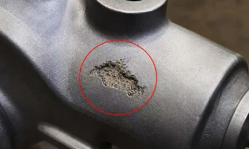
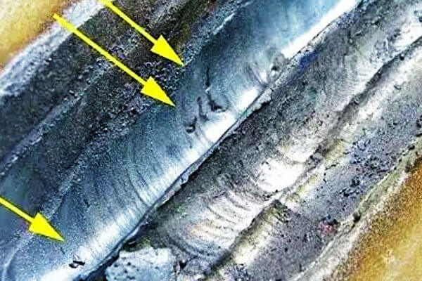
Koneistetuissa pinnoissa voi näkyä yksittäisiä pisteitä, epäsäännölliset laastarit, raitoja, tai vieraan materiaalin klustereita. Niiden ulkonäkö vaihtelee sisällytyksen lähteen mukaan.
Valkoisia tai vaaleita rakeisia hiukkasia liittyvät usein piidioksidihiekkaan tai tulenkestävään materiaaliin, kun taas harmaa, tummanharmaa, tai mustia alueita voi viitata kuonaan, oksidit, pinnoitteen jäämät, tai vaahdon hajoamisen hiilipitoisia tuotteita.
Kuitenkin, visuaalinen ulkonäkö ei yksinään voi määrittää inkluusion alkuperää luotettavasti.
Tuotannon vianmääritystä varten, metallografinen tutkimus ja, tarvittaessa, SEM/EDS-analyysi pystyy erottamaan piidioksidipitoisen hiekkahiukkasen oksidipitoisesta metallurgisesta inkluusiosta tai tulenkestävästä pinnoitepalasta.
| Havaittu vian ulkonäkö | Mahdollinen alkuperä | Tyypillinen sijainti |
| Valkoisia rakeisia täpliä | Piidioksidihiekkaa tai tulenkestäviä hiukkasia | Koneistetut pinnat, porttien lähellä |
| Harmaa tai musta epäsäännöllinen laikku | Kuona, oksidit, pinnoitteen jäämät | Sisäiset valualueet |
| Lineaariset tai halkeamamaiset sulkeumat | Pinnoitteen halkeilu, jota seuraa hiekan sisääntulo | Kuvioliitokset, porttiliitokset |
| Inkluusioklusterit | Paikallinen pinnoitteen vika tai turbulenttinen metallivirtaus | Sprue, juoksija, ingate alueita |
| Suuret sisäpuoliset ei-metalliset alueet | Voimakasta hiekan sisääntuloa tai pinnoitteen halkeilua | Lähellä porttijärjestelmää tai valusiirtymiä |
Missä kuonasulkeumia esiintyy?
Vika voi mahdollisesti esiintyä koko metallin virtausreitillä, mukaan lukien kaatokuppi, kumota, juoksija, Kuinka paljon, porttijärjestelmän liitokset, ja valuonkalo.
Silti, suurimmat riskialueet ovat yleensä paikkoja, joissa porttijärjestelmä liittyy valuun tai joissa geometria aiheuttaa äkillisiä muutoksia virtaussuunnassa tai -nopeudessa.
Se juoksijalle, juoksija-ingate, ja ingate-to-pattern -yhteydet ansaitsevat erityistä huomiota.
Nämä alueet ovat alttiina merkittäville lämpö- ja mekaanisille rasituksille kaatamisen aikana.
Jos pinnoite jossakin näistä kohdista on haljennut, huonosti sidottu, liian ohut, tai paikallisesti vaurioitunut kuvion asennuksen tai hiekkatäytön aikana, sula metalli voi suoraan koskettaa ympäröivää hiekkaa.
Kun pinnoitteen suoja on rikottu, yhdistelmä metallin paine, tyhjiöimu, ja metallin virtausvoimat voi vetää irtonaista hiekkaa ja tulenkestäviä hiukkasia nestemäiseen metalliin.
Mukana kulkeutunut materiaali kuljetetaan sitten valukappaleeseen ja voi jäädä loukkuun metallin jähmettyessä.
2. Miksi kuonan sisällyttäminen on erityisen vaikeaa Lost Foam -valussa?
Kadonnut vaahtovalu eroaa olennaisesti tavanomaisesta hiekkavalusta, koska vaahtomuovi pysyy muotin sisällä kaatoon asti.
Kuvio ei yksinkertaisesti katoa ennen kuin metalli tulee onteloon; sen sijaan, se tapahtuu lämpöhajoaminen ja höyrystyminen, kun sula metalli asteittain korvaa sen.
Tämä luo useita samanaikaisia kuljetusilmiöitä:
- Sula metalli etenee ontelon läpi.
- Polymeerikuvio hajoaa.
- Kaasun ja nesteen hajoamistuotteet kulkeutuvat tulenkestävän pinnoitteen läpi.
- Tyhjiöpaine vaikuttaa muotin täyttöön ja kaasun poistoon.
- Tulenkestävä pinnoite altistuu voimakkaalle lämpö- ja mekaaniselle kuormitukselle.
- Kuviota ympäröivän kuivan hiekan tulee säilyttää riittävä rakenteellinen eheys.
Jos pinnoite halkeilee tai menettää tarttuvuuden, etenevä metalli voi koskettaa irtonaista hiekkaa suoraan.
Jos porttijärjestelmä ei ole riittävästi suojattu, hiekka ja tulenkestävät palaset voivat päästä metallivirtaan.
Tästä syystä pelkkä pinnoitteen tulenkestävyyden lisääminen ei välttämättä ratkaise ongelmaa.
Pinnoitteen lujuus, läpäisevyys, tarttuvuus, kuivauskäyttäytyminen, pinnoitteen paksuus, porttisuunnittelu, ja tyhjiön ohjausta on tarkasteltava yhdessä.
3. Tärkeimmät syyt kuonan sisältymisvirheisiin menetetyssä vaahtovalussa
Kuona- ja hiekkasulkeumat kadonneessa vaahtovalussa ovat monitekijäiset viat yhden prosessiparametrin tuloksen sijaan.
Koko metallin virtausreitti - kaatokupista ja kanavasta juoksuputkeen, Kuinka paljon, ja lopullinen ontelo - pystyy mahdollisesti tuomaan ei-metallista materiaalia valuun.
Käytännössä, kuitenkin, porttijärjestelmän liitokset, pinnoitteen vikoja, ja alueet, joissa metallin virtausnopeus on suuri, ovat kriittisimpiä riskialueita.
Tulenkestävän pinnoitteen vika
Tulenkestävä pinnoite muodostaa ensisijaisen esteen sulan metallin ja kuivan hiekan välillä.
Jos tämä este halkeilee, kuorii, tai syöpyy, hiekka ja tulenkestävät hiukkaset voivat kulkeutua metalliin ja jäädä loukkuun valuun.
Yleisiä pinnoitteeseen liittyviä syitä ovat riittämätön lujuus huoneenlämpötilassa, riittämätön kuumavoima, epätasainen pinnoitteen paksuus, huono tarttuvuus, ja väärä kuivaus.
Erityistä huomiota tulee kiinnittää syöttöputkien liitokset, juoksuputkiliitokset, terävät kulmat, ja kuvion siirtymät, missä tasaisen pinnoitteen peittävyyden ylläpitäminen on vaikeampaa.
Sopivan kadonneen vaahtomuovin pinnoitteen pitäisi tarjota riittävästi tulenkestävyys, mekaaninen lujuus, läpäisevyys, tarttuvuus, ja lämpöiskun kestävyys koko kaatoprosessin ajan.
Suojausjärjestelmä- ja tiivistysongelmat
Suojausjärjestelmä on kriittinen hiekan inkluusiolähde, koska se tarjoaa ensimmäisen polun sulalle metallille muottiin.
Huonosti kytketty tai riittämättömästi tiivistetty putket, juoksijat, ja holkit voivat luoda aukkoja, joiden kautta kuiva hiekka pääsee metallivirtaan.
Päällystyshalkeamat porttiliitoskohdissa ovat erityisen vaarallisia, koska näillä alueilla metallivirtaus ja lämpökuormitus ovat keskittyneet.
Sen vuoksi porttijärjestelmän tulee olla riittävän jäykkä, turvalliset yhteydet, ja jatkuva tulenkestävä suoja.
Ennen kaatamista, kaatokuppi ja avoimet porttialueet tulee myös tarkistaa löysää hiekkaa, pöly, vaurioitunut pinnoite, ja vieraita hiukkasia.
Väärät kaato- ja tyhjiöparametrit
Prosessiparametrit vaikuttavat suoraan pinnoitteen mekaaniseen ja lämpökuormitukseen.
Yksi liiallinen kaatopää tai metallin virtausnopeus voi lisätä pinnoitteen eroosiota, kun taas liian korkea kaatolämpötila voi nopeuttaa lämpöhajoamista ja tulenkestävän metallin reaktioita.
Päinvastoin, liian alhaiset lämpötilat voivat aiheuttaa virheitä ja epätäydellistä täyttöä.
Tyhjiötä on myös valvottava huolellisesti. Vaikka tyhjiö on välttämätöntä hiekan tiivistämiseksi ja kaasun poistamiseksi, liian korkea alipainetaso voi vetää irtonaista hiekkaa tai pinnoitteen palasia olemassa olevien halkeamien läpi.
Hiekan ominaisuudet ovat toinen näkökohta. Väärä raekokojakauma voi lisätä hiekan tunkeutumista, eroosio, tai huono kaasunpoisto.
Optimaalinen yhdistelmä tyhjiön taso, kaatamislämpötila, täyttöaste, ja hiekan erittely sen vuoksi olisi vahvistettava kullekin seokselle ja valugeometrialle sen sijaan, että sitä sovellettaisiin yleisasetuksena.
Kuvioiden käsittely ja muovausvauriot
Inkluusiovirheet voivat syntyä ennen kaatamista, jos päällystetty vaahtomuovikuvio vaurioituu kuljetuksen aikana, kokoonpano, hiekka täyttö, tai tärinämuovausta.
Aggressiivinen hiekkakuormitus tai liiallinen tärinä voi aiheuttaa halkeamia ja lastuja kuivuneeseen pinnoitteeseen, erityisesti ohuiden osien ja porttiliitosten ympärillä.
Nämä viat voivat jäädä piiloon sen jälkeen, kun kuvio on upotettu hiekkaan, ja ne ilmenevät vasta, kun sulkeumat paljastuvat koneistuksen aikana.
Hallittu muovausjärjestys on siksi välttämätön: kuviota tulee tukea riittävästi ennen voimakkaamman tärinän käyttämistä, ja porttijärjestelmää ei saa taivuttaa tai häiritä mekaanisesti tiivistyksen aikana.
Sulan metallin puhtaus
Kaikki sulkeumat eivät ole peräisin muotista. Oksidit, kuona, tulenkestäviä hiukkasia, ja muut ei-metalliset sulkeumat, jotka ovat jo sulassa metallissa voi myös jäädä loukkuun täytön aikana.
Tehokas valvonta vaatii siksi huomiota koko metallinkäsittelyketjuun, mukaan lukien sulatus, kuonan poisto, lämpötilan säätö, rokotus tai hoito tarvittaessa, siirtää, ja kaatamalla.
Kuonan kuoriminen, suodatus, ja asianmukaisesti suunnitellut suojaus- tai kuonanpoistoominaisuudet voivat edelleen vähentää onteloon pääsevän ei-metallisen materiaalin määrää.
4. Tapaustutkimukset: Kuonan sisältymisen epäonnistumiset ja korjaavat toimenpiteet LangHe-valimossa
At Langhe -valimo, Kuonan ja hiekan torjuntaa käsitellään pikemminkin prosessiteknisenä ongelmana kuin lopputarkastuksen ongelmana.
Kadonneessa vaahtomuovivalussa, inkluusiovirheet voivat johtua tulenkestävästä pinnoitteesta, kuvion kokoonpano, muovaustoiminta, tyhjiöjärjestelmä, porttisuunnittelu, tai sulan metallin puhtaus.
Siten, Tehokas korjaava toimenpide edellyttää vian morfologian korreloimista vian sijainnin ja todellisten prosessiolosuhteiden kanssa.
Seuraavat kolme tapausta ovat tyypillisiä LangHe Valimotuotannon skenaariot harmaata valurautaa, rauta- rauta, ja hiiliteräksestä hävinneitä vaahtovaluja.
Tapaukset osoittavat, kuinka systemaattinen perussyyanalyysi voi muuttaa toistuvat inkluusio-ongelmat mitattavissa oleviksi prosessiparannuksiksi.
Asia 1: Harmaa valurautainen hydrauliventtiilin runko
Tausta
LangHe Valimo valmisti harmaavalurautaista hydrauliventtiilirungoa käyttämällä kadonnutta vaahtovaluprosessia.
Komponentit sisälsivät useita tarkkuuskoneistettuja tiivistyspintoja ja ne altistettiin 100% painetestaus klo 1.6 MPA.
Koska tiivistyspinnat koneistettiin myöhemmin, suhteellisen pienet sisäiset sulkeumat voivat paljastua ja aiheuttaa vuotoja.
Vian oireet
Alkuperäinen ensikierron tuotto oli noin 68%. Suurin osa painetestin epäonnistumisista jäljitettiin koneistetuille venttiili-istukan pinnoille paljastuneisiin maanalaisiin sulkeutumiin.
Porttijärjestelmän tarkastus antoi tärkeän vihjeen. Shakeoutin jälkeen, Paikallista pinnoitteen delaminaatiota havaittiin toistuvasti ympärillä ingate-to-casting -risteys.
Kun juoksijan osat murtuivat tarkastusta varten, murtuman pinnalla oli näkyvissä valkoisia rakeisia hiukkasia, osoittavat mukana kulkeutuneen tulenkestävän tai hiekkamateriaalin läsnäolon.
Perussyyanalyysi
Tutkimuksessa havaittiin kaksi ensisijaista vaikuttanutta tekijää.
Ensimmäinen, tulenkestävä pinnoite holkkiliitoksen ympärillä oli huomattavasti ohuempi kuin kuvion litteissä osissa.
Liitoskohdan geometria sai pinnoitteen valumaan epätasaisesti kastelun aikana, tuloksena paikallisesti heikko este.
Toinen, muottia käytettiin suhteellisen korkealla vakiotyhjiötasolla noin 0.045 MPA.
Kun pinnoite risteyksessä oli heikentynyt, paine-ero edisti irtonaisen hiekan liikkumista viallisen alueen läpi täytön aikana.
Vika ei siis johtunut pelkästään tyhjiöstä. Pikemminkin, todellinen vikamekanismi oli:
epätasainen pinnoitteen paksuus → paikallinen pinnoitteen heikkous → tyhjiöavusteinen hiekan sisäänpääsy → sulkeutuminen → koneistusaltistus → painetestivuoto.
Korjaavat toimet
LangHe Valimo toteutti kaksi suurta prosessimuutosta. Toinen vahvistettu pinnoitekerros levitettiin erityisesti porttiliitoksille ja muille suuren riskin siirtymäalueille, lisäämällä paikallista pinnoitteen paksuutta noin 60%.
Myös alipainejärjestelmä vaihdettiin vakiopainekäytöstä ohjattuun kaksivaiheiseen profiiliin.
Aluksi tyhjiö pidettiin noin 0.025 MPA varhaisen täyttövaiheen aikana ja lisääntyi asteittain noin 0.038 MPA täytön viimeisen osan aikana.
Tarkoituksena oli välttää liiallisen paine-eron kohdistamista metallin tullessa ensin haavoittuvalle porttialueelle, tarjoten silti riittävän tyhjiön myöhemmin täyttöprosessissa muotin stabiiliuden ja kaasun poistamiseksi.
Tulos
Painetestin läpäisynopeus nousi 68% kohtaan 92%, kun taas kuonaa- ja hiekkainkluusioon liittyvä romu väheni noin 71%.
Tapaus osoitti, että paikallinen pinnoitesuunnittelu ja dynaaminen tyhjiön hallinta voisivat olla tehokkaampia kuin pelkkä pinnoitteen kokonaispaksuuden lisääminen tai tasaisen korkean tyhjiötason ylläpitäminen koko kaatamisen ajan..
Asia 2: Pallorautainen autojen alustan kiinnike
Tausta
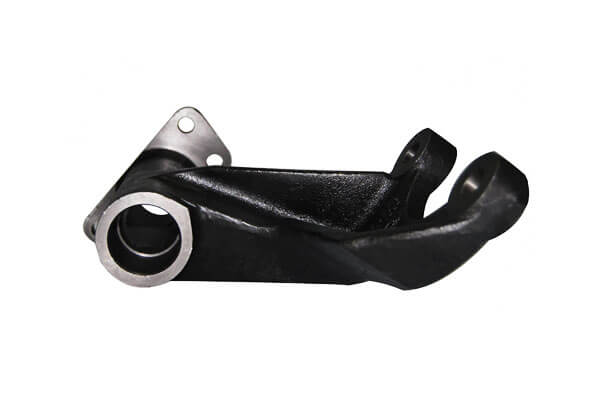
LangHe Valimossa valmistetut pallografiittivalurautaiset autojen alustan kiinnikkeet käyttämällä kadonnutta vaahtomuovivalua.
Komponentit sisälsivät paljaita ulkopintoja, jotka myöhemmin vastaanottivat elektroforeettinen pinnoite (E-pinnoitus).
Koska lopullisella maalatulla pinnalla oli tiukat ulkonäkövaatimukset, suhteellisen pienet pinnan pinnan viat voivat tulla näkyviin pinnoituksen jälkeen.
Vian oireet
Aluksi havaittiin ajoittainen pintavikaongelma elektroforeettisen maalauksen jälkeen. Pieniä kuonamaisia rakkuloita ilmestyi pääasiassa kiinnikkeiden yläpinnalle, joiden esiintymistiheys on noin 22%.
Mielenkiintoista, viat eivät jakaantuneet satunnaisesti.
He olivat keskittyneet alueelle, joka sijaitsee vastapäätä ensisijaista rautaa, viittaa siihen, että vika liittyi ei-metallisen materiaalin täyttökäyttäytymiseen tai liikkumiseen eikä se olisi tasaisesti jakautunut metallurginen inkluusio.
Perussyyanalyysi
Kuviokokoonpanon tutkiminen paljasti, että johtimien ja juoksuputkien välisessä liitoksessa käytettiin löysää puristusliitosta. Tärinämuovauksen aikana, nivel voisi liikkua hieman, luoda paikallista aukkoa.
Samaan aikaan, hiekkatäytön aikana käytetty alkuvärähtelyamplitudi oli liian aggressiivinen.
Koska vaahtokokoonpanon pystysuorat pinnat olivat riittämättömästi tuetut tässä vaiheessa, kuivuneeseen pinnoitteeseen kehittyneet mikrohalkeamat.
Näiden kahden ehdon yhdistelmä loi polun hiekalle pääsylle:
löysä porttiliitos + aggressiivinen varhainen tärinä → pinnoitteen vauriot ja aukko → hiekan kulkeutuminen täytön aikana → sisäiset sulkeumat → pinnan rakkuloita E-pinnoituksen jälkeen.
Tämä havainto selitti myös, miksi tavanomainen silmämääräinen tarkastus ravistelun jälkeen ei johdonmukaisesti tunnistanut ongelmaa: Suurin osa vaurioista sijaitsi hiekan alla ennen kaatamista, eikä se ollut helposti näkyvissä valun jälkeen.
Korjaavat toimet
LangHe Valimo otti käyttöön integroidun vahvistusholkin kanavan ja juoksuputken välisessä liitoksessa ja lisäsi tulenkestävää pinnoitetta liitoksen ympärille parantaakseen sekä mekaanista vakautta että pinnoitteen jatkuvuutta..
Tärinäohjelma jaettiin myöhemmin kahteen vaiheeseen. Ensimmäisen hiekkapeitoksen jälkeen, kuvio altistettiin noin 5 sekuntia matalaamplitudista tärinää.
Suuremman amplitudin tiivistys otettiin käyttöön vasta sen jälkeen, kun vaahtokokoonpano oli riittävästi ympäröity ja tuettu hiekalla.
Ennen lopullista muotin sulkemista otettiin käyttöön myös erityinen suutinkorkin tiivistysmenettely, jotta irtonainen hiekka ei pääse ylemmän suojajärjestelmän läpi..
Tulos
E-pinnoituksen jälkeinen pintavikaprosentti laski noin 22% kohtaan 4%. Vikaan liittyvät asiakkaan hylkäyserät eliminoitiin.
Tapaus havainnollistaa tärkeää periaatetta vaahtomuovivalussa: muovausvärähtely ei ole vain tiivistysparametri; se voi vaikuttaa suoraan pinnoitteen eheyteen ja siten valun puhtauteen.
Optimaalisen tärinäprofiilin tulee tarjota riittävä hiekan tiivistys vahingoittamatta pinnoitettua kuviota mekaanisesti.
Asia 3: Pumpun kotelo hiiliteräksestä
Tausta
LangHe Valimo tutki kadonneen vaahtomuovin käyttöä hiiliteräspumppukoteloissa vaihtoehtona tavanomaiselle hiekkavalulle.
Tavoitteena oli vähentää koneistusvaraa ja parantaa suurten sisäisten virtauskanavien mittayhteyttä.
Komponenteilla oli laajat koneistetut sisäpinnat, mikä tekee sisäisen osallisuuden valvonnan erityisen tärkeäksi.
Vian oireet
Alkuperäiset tuotantokokeet osoittivat laajalle levinneitä hajaantuneita sulkeumia koneistetuilla sisäisillä virtauspinnoilla. Tuloksena oleva romumäärä saavutti noin 35%.
Porttijärjestelmän tarkastus paljasti voimakasta tulenkestävää eroosiota ja pinnan suonet juoksuputkessa.
Vikajakauma viittasi siihen, että ongelma liittyi ensisijaisesti pinnoitteen hajoaminen teräksen täytön aikana, mieluummin kuin vain sulan metallin kuonalla.
Perussyyanalyysi
Ensimmäinen suuri ongelma oli harmaaraudan hävikkivaahtovalua varten kehitetyn pinnoitusjärjestelmän käyttö.
Sen tulenkestävyys ja kuumalujuus eivät riittäneet hiiliteräkseen liittyvään merkittävästi korkeampaan lämpökuormitukseen.
Kaatamisen aikana, pinnoite hajosi ja kului osittain korkean lämpötilan yhteisvaikutuksista, lämmösokki, ja metallin virtausvoimat.
Toinen ongelma oli liian tehokas kaatopää. Eräs 1-tonnin kauha synnytti suhteellisen suuren metallin virtausnopeuden kanavaa täytettäessä, jo ennestään herkän pinnoitteen mekaaninen eroosio lisääntyy.
Yhdistetty mekanismi oli siis:
riittämätön tulenkestävä järjestelmä → pinnoitteen hajoaminen korkeassa lämpötilassa → liiallinen metallivirtauksen eroosio → tulenkestäviä hiukkasia pääsee teräkseen → sisäiset sulkeumat.
Korjaavat toimet
LangHe Valimo korvasi perinteisen rautalaatuisen pinnoitteen a runsaasti alumiinioksidia sisältävä tulenkestävä pinnoite, joka on suunniteltu erityisesti teräsvaahtomuovivalua varten.
Uusi pinnoite paransi huomattavasti tulenkestävyyttä ja kuumalujuutta teräksen kaatoympäristöön.
Myös tehollinen kaatokorkeus pieneni. Otettiin käyttöön pohjakaappaus, suuttimen ollessa mahdollisimman lähellä kaatokuppia tarpeettoman metallin kiihtyvyyden ja turbulenssin vähentämiseksi.
Lopuksi, kaatolämpötilaa laskettiin noin 1560°C - 1510 °C, pysyen hiiliteräslaadun ja valugeometrian vakiintuneen prosessiikkunan sisällä.
Nämä muutokset toteutettiin koordinoituna pakettina eikä yksittäisinä mukautuksina.
Tulos
Sisäinen kuona-inkluusio romun määrä laski noin 35% kohtaan 8%, tehdä menetetty vaahtoprosessi kaupallisesti kannattavaksi pumppupesäsovelluksessa.
Tapaus osoittaa myös miksi pinnoitteen valinnan on oltava seoskohtainen.
Tulenkestävän pinnoitteen, joka toimii riittävästi harmaan raudan kanssa, ei voida automaattisesti olettaa tarjoavan riittävän lämpö- ja kemiallisen stabiilisuuden teräkselle.
Seoksen kaatolämpötilan noustessa, pinnoitteen tulenkestävyys, kuuma voima, lämpöiskun kestävyys, ja metallin/pinnoitteen yhteensopivuus tulee yhä tärkeämmäksi.
Kolmen tärkeimmät oppitunnit LangHe Valimokotelot
Nämä kolme tapausta koskivat erilaisia metalliseoksia ja erilaisia valugeometrioita, mutta ne paljastavat yhteisen kaavan: Kuonan sisällyttäminen on yleensä seurausta useiden prosessimuuttujien välisestä vuorovaikutuksesta.
| Asia | Ensisijainen vikamekanismi | Kriittinen prosessimuuttuja | Korjaava strategia | Tulos |
| Harmaarautainen hydrauliventtiilirunko | Hiekan sisääntulo heikon pinnoitteen läpi | Pinnoitteen paksuus + tyhjiö | Vahvistettu pinnoite ja porrastettu tyhjiö | Ensisijainen sato: 68% → 92% |
| Pallorautaa rungon kannake | Pinnoitevaurio muovauksen aikana | Porttiliitoksen lujuus + värähtely | Vahvistettu liitos ja porrastettu tärinä | Pintavirheet: 22% → 4% |
| Pumpun kotelo hiiliteräksestä | Korkean lämpötilan pinnoitteen eroosio | Pinnoitteen tulenkestävyys + kaatamalla päätä | Korkea alumiinioksidipinnoite ja alennettu kaatokorkeus | Sisällön romu: 35% → 8% |
Tärkein johtopäätös on se ei ole universaalia "inkluusiota estävää asetusta" kadonneelle vaahtomuovivalulle.
Sopiva pinnoitusjärjestelmä, tyhjiöprofiili, tärinäohjelma, kaatamislämpötila, porttisuunnittelu, ja hiekan spesifikaatiot on sovitettava seos- ja valugeometriaan.
Tästä syystä, LangHe Valimon lähestymistapa keskittyy perussyyn tunnistaminen, prosessi-ikkunan optimointi, ja vian sijainnin analyysi sen sijaan, että luottaisimme pelkästään lopulliseen silmämääräiseen tarkastukseen.
Tämä menetelmä on erityisen arvokas hydraulikomponenteille, autojen valukappaleet, pumppukotelot, venttiilirungot, ja muut osat, joissa sisäiset sulkeumat saattavat tulla näkyviin vasta koneistuksen tai toimintatestauksen jälkeen.
5. Systemaattiset ehkäisy- ja lieventämisstrategiat
Kuonan sulkeumien hallinta kadonneessa vaahtovalussa vaatii koordinoitua prosessinhallintaa yksittäisen korjaavan toimenpiteen sijaan.
Tehokkain tapa on säilyttää pinnoitteen eheys, suojaa kuviota muovauksen aikana, ohjaa metallin virtausta ja tyhjiötä, ja parantaa sulan metallin puhtautta koko tuotantosyklin ajan.
Optimoi tulenkestävä pinnoite
Tulenkestävä pinnoite on ensisijainen este, joka erottaa sulan metallin kuivasta hiekasta.
Sen pitäisi olla riittävä tulenkestävyys, läpäisevyys, tarttuvuus, huoneenlämpötilan lujuus, ja kuuma voima.
Levitä pinnoite tasaisesti useissa kerroksissa, riittävällä kuivauksella kerrosten välillä. Porttiliitoksia ja muita korkea-eroosiota aiheuttavia alueita tulisi vahvistaa lisää.
Jokainen päällystetty kuvio tulee tarkastaa ennen muovausta, ja kuvioita, joissa on näkyviä halkeamia, kuorinta, tai delaminaatio tulee korjata tai hylätä.
Ohjauskuvion kokoonpano ja muovaus
Vaahtomuovikuvion ja porttijärjestelmän tulee pysyä mekaanisesti vakaana hiekkatäytön ja tärinän aikana.
Porttiliitokset voidaan tarvittaessa vahvistaa sopivilla tuilla tai holkeilla. Hiekkaa tulee aluksi lisätä varovasti, ja tärinän tulee alkaa alhaisella amplitudilla.
Korkeampaa tärinän voimakkuutta tulisi käyttää vasta, kun kuvio on riittävästi ympäröity hiekalla.
Erityistä varovaisuutta tarvitaan ympärillä kumota, juoksijoiden risteyksiä, ja ingates, jossa mekaaninen liike voi murtaa tulenkestävän kerroksen.
Suutin tulee myös sulkea kunnolla ja kaatokuppi puhdistaa välittömästi ennen kaatamista.
Ohjaa kaatolämpötilaa ja metallin virtausta
Kaatoolosuhteiden tulisi minimoida pinnoitteen eroosio säilyttäen samalla riittävä juoksevuus ja täydellinen muotin täyttö.
Liian suuri kaatokorkeus, turbulenssi, ja lämpötila voi lisätä tulenkestävän aineen hajoamista ja inkluusiota.
| Kevytmetallityyppi | Tyypillinen kaatolämpötila | Tyypillinen kaatoaika* |
| Harmaa valurauta | 1380-1420 °C | 10-20 s |
| Rauta- rauta | 1420-1450 °C | 12-25 s |
| Hiili / niukkaseosteinen valuteräs | 1480-1560 °C | 15–30 s |
*Tyypilliset viitearvot 300–500 kg:n kaatoerälle; todelliset parametrit tulee määrittää seoslaadun mukaan, valumassaa, seinämän paksuus, porttisuunnittelu, ja varusteet.
Kauhan kapasiteetin tulee olla kohtuullisesti sovitettu valukappaleeseen. Kaatoputken pitäminen lähellä suutinkuppia vähentää vapaan pudotuksen korkeutta ja iskunopeutta.
Kaatamisen pitäisi myös jäädä tasainen ja jatkuva, välttää tarpeettomia keskeytyksiä tai äkillisiä virtauspiikkejä.
Optimoi tyhjiön ohjaus
Tyhjiö on välttämätön vaahtomuovivalussa, koska se parantaa kuivahiekkatiivistymistä, helpottaa kaasun poistoa, ja tukee muotin täyttöä.
Kuitenkin, liiallinen alipaine voi vetää hiekkaa tai pinnoitteen palasia olemassa olevien halkeamien läpi.
Monille rautavaluille, toiminta-alue noin 0.025-0,040 MPa käytetään yleisesti lähtökohtana. Optimaalinen arvo riippuu voimakkaasti valugeometriasta ja prosessiolosuhteista.
Porrastettu tyhjiöprofiili voi olla edullinen: suhteellisen kohtalainen tyhjiö alkutäytön aikana vähentää pinnoitteen eroosiota, jota seuraa lisääntynyt tyhjiö täytön edetessä.
Tyhjiötä tulee siksi käsitellä a optimoitava prosessimuuttuja, ei vain maksimoida.
Paranna porttia ja kuonan pidätystä
Portin suunnittelun tulisi edistää stabiilia täyttöä samalla kun estetään ei-metallisten materiaalien pääsy kriittisille valualueille.
Seoksesta ja valugeometriasta riippuen, järjestelmä voi sisältää kuonaloukut, kuori osia, asutusalueita, suodattimet, tai erilliset keräysalueet.
Keraamiset vaahtosuodattimet voivat tarjota ei-metallisten sulkeumien lisähallinnan, vaikka niiden käyttöä on arvioitava vaaditun virtausnopeuden ja valulämpötilan perusteella.
Oikea porttisuunnittelu on erityisen tärkeää painetta sisältäville ja pitkälle koneistetuille komponenteille, joissa pienetkin sulkeumat voivat aiheuttaa toimintahäiriöitä.
Säilytä sopiva hiekan laatu
Kuivan hiekan tulee tarjota tasapaino läpäisevyys, tiivistymiskäyttäytyminen, pinnan laatu, ja metallin läpäisynkestävyys.
Liian karkea hiekka voi lisätä tunkeutumista ja inkluusioon liittyviä vikoja, liiallinen hienoaines voi heikentää kaasun poistumista ja muuttaa homeen käyttäytymistä.
Moniin rautapitoisten vaahtomuovisovelluksiin, 30/50 verkkopesty silikahiekka on yleisesti käytetty viitemääritys.
Todellinen raekokojakauma tulee valita valu- ja pinnoitusjärjestelmän mukaan, sakkojen säännöllisellä poistamisella, pöly, ja rikkoutuneita pinnoitehiukkasia.
Paranna sulan metallin puhtautta
Ulkoiset hiekka- ja pinnoitussulkeumat ovat vain osa ongelmaa. Oksidit ja kuona, jotka ovat jo sulassa metallissa, voivat tulla lisälähteiksi ei-metallisten sulkeumien lähteiksi.
Tehokas ohjaus alkaa siis sulatusvaiheessa ja jatkuu siirron ja kaatamisen kautta.
Keskeisiä toimenpiteitä ovat mm kuonan poisto, sopiva sulakäsittely, ohjattu siirto, puhtaat kauhat, ja suodatus, jos se on teknisesti tarkoituksenmukaista.
Yleisenä tavoitteena on estää molemmat eksogeeniset sulkeumat muotista ja endogeeniset inkluusiot syntyy sulassa metallissa joutuessaan valmiiseen valuun.
6. Johtopäätös
Kuonan sisältämät viat kadonneessa vaahtovalussa ne johtuvat ensisijaisesti sulan metallin vuorovaikutuksesta, tulenkestävä pinnoite, kuivaa hiekkaa, vaahdon hajoamistuotteet, tyhjiöpaine, ja metallurgiset sulkeumat.
Yleisimpiä mekanismeja ovat pinnoitteen halkeilu tai halkeilu, heikot porttijärjestelmän liitokset, hiekkaa, liiallinen metallivirtauksen eroosio, väärä alipainesäätö, epävakaat muovaustoiminnot, ja sulan metallin riittämätön puhtaus.
Reaalimaailman tuotantotapaukset osoittavat johdonmukaisesti, että yksittäiset yhden parametrin säädöt tuottavat vain marginaalista parannusta.
Jatkuvasti alhaisten kuonapitoisuuksien saavuttaminen edellyttää kokonaisvaltaista lähestymistapaa: optimoitu pinnoitteen koostumus ja käyttö, tiukka muovaus- ja käsittelykuri, oikein suunniteltu portti, jossa on kuonanpidätysominaisuudet, kalibroidut prosessiparametrit ja jatkuva sulan metallin puhtauden valvonta.
Toteutettuna järjestelmällisesti kaikissa tuotantovaiheissa, nämä toimenpiteet voivat vähentää kuonaan liittyvää romua erittäin alhaiselle tasolle, mikä tekee menetetystä vaahtomuovivalusta käyttökelpoisen jopa vaativia koneistettuja komponentteja varten.