Comprehensive metal cutting services: turning, drilling, boring, planing, broaching, and milling. Precision machining for custom industrial metal parts.
We’ve gone from manual mills and lathes to five-axis CNC centres and additive manufacturing.
But through all of it, six processes have remained the backbone of metal cutting: turning, drilling, boring, planing, broaching, and milling.
Every other method—EDM, laser, waterjet—is a specialist. These six are the generalists. Master them, and you can make almost anything.
In this article, I’ll walk you through the core principle of each process, the precision you can realistically expect, and the applications where each one shines.
I’ll also share some hard-won lessons from the shop floor—the kind of things you only learn after scrapping a few parts.
1. Turning: The Primary Process for Rotational Components
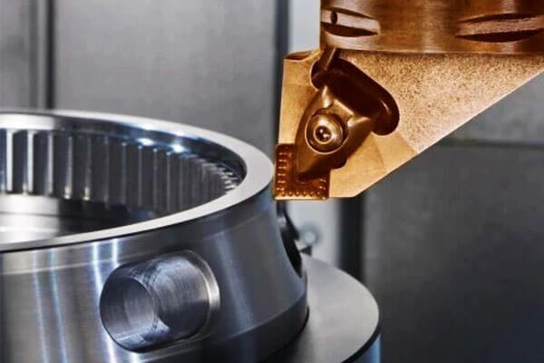
Turning is one of the most widely used machining processes for producing rotational components.
During conventional turning, the workpiece rotates while a stationary cutting tool moves along the axial or radial direction to remove material.
This arrangement makes turning particularly effective for shafts, bushings, sleeves, pins, and other components with cylindrical or conical features.
Working Principle and Common Operations
The cutting tool removes material from the rotating workpiece to generate the required surface.
By changing the tool geometry and feed direction, a lathe can perform several operations:
- External turning: Produces cylindrical or stepped outer surfaces.
- Internal turning: Enlarges or finishes an existing bore.
- Facing: Produces a flat end face perpendicular to the rotational axis.
- Taper turning: Creates conical surfaces.
- Grooving and parting: Produces grooves or separates a component from the stock.
- Threading: Generates internal or external threads using a suitable tool and synchronized feed.
- Form turning: Produces specific profiles using an appropriately shaped tool.
Turning can be performed on conventional lathes, CNC turning centers, and mill-turn machines.
CNC equipment is particularly valuable when components contain multiple diameters, grooves, threads, and precision features that must maintain consistent relationships.
Workholding and Accuracy Control
Workholding has a direct influence on turning accuracy. A three-jaw self-centering chuck provides fast loading and is suitable for many round components.
A four-jaw independent chuck allows individual jaw adjustment and is useful for irregular workpieces or applications requiring precise alignment.
Between-center turning is often preferred for long shafts when maintaining alignment between multiple sections is critical.
For thin-walled sleeves or precision bores, excessive chucking force can deform the workpiece.
In these cases, a properly designed expanding mandrel, soft jaws, or another distributed-clamping arrangement may provide better dimensional stability.
Typical Precision and Applications
Conventional turning commonly achieves IT7–IT8 dimensional tolerance grades under suitable conditions.
Precision CNC turning can achieve tighter tolerances, depending on the machine, material, workholding, cutting tool, and inspection method.
Typical applications include:
- Shafts, axles, pins, and threaded fasteners
- Bushings, sleeves, and bearing seats
- Hydraulic cylinders and valve components
- Rotating equipment parts and precision fittings
Turning is generally the first choice when the dominant features are rotational.
For components with extensive flat surfaces, cross-holes, or complex three-dimensional geometry, milling or combined mill-turn machining may be more efficient.
Shop-floor tip:
Don’t underestimate the importance of tool geometry. A positive rake angle reduces cutting forces and improves surface finish on aluminium.
For steel, a slight negative rake can extend tool life. And always check your centre height—being a few thousandths off will cause taper and poor finish.
2. Drilling and Boring: Two Essential Hole-Machining Processes
Hole machining is fundamental to mechanical manufacturing. Drilling and boring are often used together, but they serve different purposes.
Drilling primarily creates a hole, while boring enlarges and corrects an existing hole to improve its size, geometry, and positional relationship.
Drilling: Creating Holes in Solid Material
Drilling uses a rotating drill, commonly a twist drill, to produce a hole in solid material. The drill rotates while advancing axially into the workpiece.
It is an efficient process for producing bolt holes, oil passages, mounting holes, and preliminary holes for subsequent machining.
However, drilling does not automatically produce a highly accurate hole.
The drill can wander because of uneven cutting edges, poor centering, an inclined entry surface, insufficient rigidity, or inconsistent cutting forces. Chip evacuation also becomes increasingly difficult as hole depth increases.
In practical production, several measures help improve drilling performance:
- Face or spot the entry surface when appropriate.
- Use a suitable center drill or spot drill to establish the entry position.
- Ensure that both cutting edges are correctly ground and balanced.
- Select the correct drill geometry, cutting speed, and feed for the material.
- Provide effective chip evacuation, particularly for deep holes.
- Use a drill jig or machine probing when positional accuracy requires additional control.
Precision grades:
As-drilled holes typically achieve IT10 to IT12 with Ra 12.5–6.3 µm. The hole may be oversized, out-of-round, and not perfectly straight. For precision work, drilling is only the first step.
The classic drill–ream sequence:
For holes requiring IT7–IT8 and Ra 1.6–0.8 µm, follow drilling with a reamer. For even higher precision (IT6 and Ra 0.4 µm), use drilling → boring → reaming, or drilling → internal grinding.
Shop-floor tip:
Drill wander is the enemy. Always spot-drill first with a short, stiff centre drill. For deep holes, use a peck-drilling cycle to clear chips.
And keep your drill sharp—a dull drill will work-harden the surface and make subsequent machining difficult.
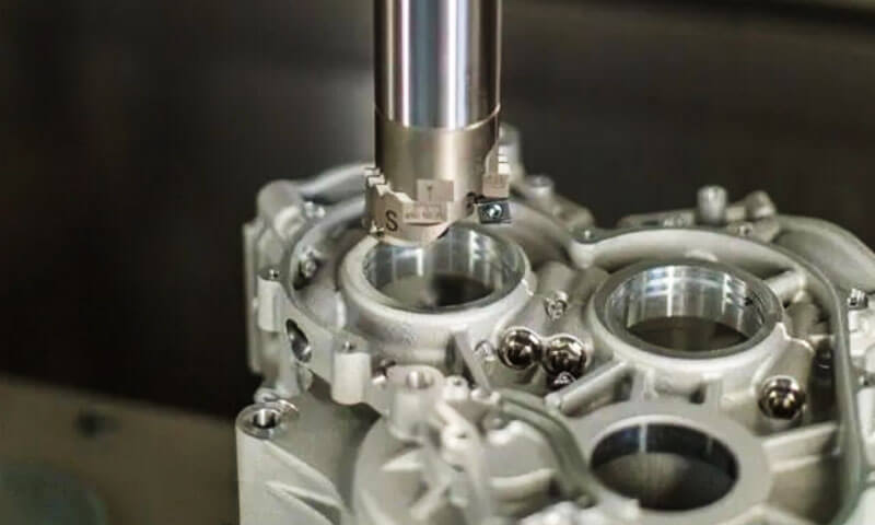
Boring: Improving Hole Size, Geometry, and Position
Boring removes material from the internal surface of an existing hole using a single-point boring tool or a suitable multi-edge system. Unlike drilling, it does not normally create a hole directly from solid material.
Boring is especially useful when the hole must meet strict dimensional requirements or maintain a controlled relationship with other features.
It is widely used for engine housings, pump bodies, transmission cases, valve bodies, and other components containing precision bores.
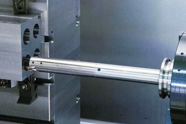
The principal advantages of boring include:
- Dimensional correction: Adjusts an existing hole to its required diameter.
- Geometric improvement: Helps control roundness, cylindricity, and straightness.
- Positional accuracy: Establishes the hole relative to controlled machine or fixture datums.
- Large-diameter capability: Produces bores that are impractical to drill directly.
Precision grades:
Boring can achieve IT7 to IT6 and Ra 1.6–0.4 µm. With a floating boring head, you can hold size and roundness within a few microns. It’s also excellent for correcting the positional errors left by drilling.
Shop-floor tip:
Boring bars are prone to deflection, especially when overhung. Use the largest bar that fits, keep overhang to a minimum, and use a carbide or cermet insert with a small nose radius for finishing.
For deep bores, use a boring bar with damping (anti-vibration) technology—it’s a game-changer.
3. Planing: An Economical Solution for Large Flat Surfaces
Planing is a conventional machining process that uses relative linear reciprocating motion between the cutting tool and workpiece.
Depending on the machine configuration, either the tool or the workpiece performs the principal cutting stroke.
Material is removed during the cutting stroke, while the return stroke is generally non-cutting.
Although planing is less common in modern high-volume production, it remains useful for large workpieces, maintenance operations, and applications where dedicated high-productivity equipment is not justified.
Working Principle and Equipment
Common planing machines include:
- Shaper: The cutting tool reciprocates across a relatively small workpiece.
- Planer: The workpiece typically moves beneath a cutting tool, making the machine suitable for large and heavy components.
- Slotter: A vertical reciprocating tool produces internal keyways, slots, and certain internal profiles.
Planing can produce flat surfaces, steps, grooves, and selected angular surfaces.
It is particularly useful when a component is too large or awkward to machine economically using conventional milling equipment.
Precision and Process Limitations
Planing machines have relatively simple tooling and can accommodate a wide range of workpieces.
However, the reciprocating motion introduces acceleration and deceleration, while the return stroke removes no material. These factors limit cutting speed and overall productivity.
Typical planing operations may achieve IT9–IT11 dimensional grades, with better results possible under favorable conditions.
Surface roughness commonly falls around Ra 1.6–6.3 μm, depending on tool geometry, feed, material, and machine condition.
Planing is suitable for:
- Large machine beds and guide surfaces
- Heavy structural components
- Flat faces and straight grooves
- Repair and maintenance work
- Single-piece and small-batch production
Shop-floor tip:
Planing is slow and has an idle return stroke, so it’s rarely economical for production. But for a one-off machine bed that’s too big for a mill, it’s often the only option.
Make sure the tool is sharp and the clapper box is functioning—if the tool drags on the return stroke, you’ll ruin the surface.
4. Broaching: High-Productivity Machining for Repetitive Profiles
Broaching is a machining process that uses a specialized multi-tooth tool called a broach.
The teeth increase progressively in height, allowing successive teeth to remove small amounts of material until the required profile is produced.
Unlike conventional milling or planing, which may require several passes to generate a feature, broaching can often complete the entire profile in a single stroke or continuous pass.
Working Principle
Each broach tooth removes a controlled portion of the machining allowance.
The first teeth perform rough cutting, intermediate teeth remove additional material, and the final teeth establish the finished dimensions and surface.
Broaching can be divided into two main categories:
- Internal broaching: Produces internal keyways, splines, polygonal holes, and other profiles. The workpiece generally requires a preliminary hole through which the broach can pass.
- External broaching: Produces external profiles, flats, grooves, and complex contours on the outside of a component.
The process is particularly effective when the required geometry is repeated across large production batches.
Precision and Tooling Considerations
Broaching commonly achieves IT7–IT9 tolerance grades, with IT7–IT8 achievable for suitable applications and well-controlled tooling.
Surface roughness around Ra 0.4–1.6 μm is possible, depending on the material, tool design, and process conditions.
Its main advantage is repeatability. Once the broach, fixture, and machine parameters are properly established, the process can deliver consistent dimensions with relatively short cycle times.
However, broaches are expensive, and each tool is designed for a particular profile and dimensional requirement.
Tool design, manufacturing, maintenance, and replacement costs must therefore be considered during process planning.
Broaching is commonly used for:
- Internal and external splines
- Keyways and polygonal holes
- Transmission and automotive components
- Repetitive production of precision profiles
- Components requiring consistent geometry across large batches
Shop-floor tip:
Broaching is expensive because the tool is custom-made for each profile. It only makes sense for high-volume production (thousands of parts).
If you need a keyway in a one-off shaft, use a slotter or a broach on a lathe—it’s slower but far cheaper.
5. Milling: The Most Versatile Metal-Cutting Process
Milling is one of the most widely used processes in modern manufacturing. A rotating multi-edge cutter removes material while the workpiece or machine table provides the required feed motion.
On CNC machining centers, coordinated movement across multiple axes enables the production of complex surfaces and geometries.
Milling is suitable for a broad range of materials, including aluminum alloys, stainless steel, alloy steel, titanium, brass, and engineering plastics.
However, tool geometry, cutting parameters, workholding, and coolant strategy must be adapted to the material.
Common Milling Operations
Milling can produce a wide variety of features:
- Face milling: Produces flat surfaces perpendicular to the cutter axis.
- Peripheral milling: Uses the cutter circumference to machine surfaces and slots.
- End milling: Produces pockets, shoulders, profiles, and narrow features.
- Slot milling: Creates keyways, T-slots, and other grooves using suitable cutters.
- Profile milling: Follows a specified contour to generate two-dimensional or three-dimensional geometry.
- Cavity milling: Removes material from pockets and complex internal features.
- Thread milling: Generates internal or external threads using a suitable milling toolpath.
Modern CNC machining centers can combine these operations in a single setup, reducing handling and helping maintain positional relationships between features.
Conventional Milling, Climb Milling, and Tool Engagement
In conventional milling, also known as up milling, the chip thickness increases from approximately zero toward its maximum as the cutting edge engages the workpiece.
In climb milling, or down milling, chip thickness generally starts at its maximum and decreases toward zero.
Climb milling often produces a better surface finish and can reduce rubbing under suitable conditions.
It is commonly preferred on modern CNC machines with effective backlash control and adequate rigidity.
However, climb milling is not automatically the best choice for every setup. Machine condition, workpiece rigidity, scale or surface condition, cutter engagement, and fixture stability must all be considered.
Typical Precision and Applications
Conventional milling commonly achieves IT8–IT10 grades, while controlled CNC milling and finishing operations can reach IT7 or tighter tolerances on suitable features.
Surface roughness around Ra 1.6–3.2 μm is common in many finishing applications, although finer finishes are possible.
Milling is widely used for:
- Flat surfaces, steps, and mounting faces
- Pockets, slots, and complex cavities
- Mold and die components
- Precision housings and brackets
- Engine, pump, and valve components
- Multi-face components requiring CNC machining
Its greatest strength is versatility. When a component includes several different features, CNC milling can often combine them into a controlled sequence, reducing setup changes and improving overall manufacturing efficiency.
Shop-floor tip:
Rigidity is everything. Keep the tool as short as possible, use the largest diameter cutter that fits the feature, and don’t skimp on workholding.
I’ve seen more chatter problems solved by improving the fixture than by changing the cutter.
Final Thoughts: The Right Tool for the Right Job
There is no “best” metal-cutting process. There is only the most appropriate one. A shaft should be turned, not milled. A precision bore should be bored, not drilled.
The complex keyway in a thousand parts should be broached, not milled. A one-off machine bed should be planed if you don’t have a big enough mill.
The veteran machinist knows that the choice is about balancing geometry, precision, volume, and cost.
You can’t make a cylindrical part on a mill as efficiently as on a lathe. You can’t hold a micron on a drill press. You can’t broach a one-off part economically.
So next time you look at a drawing, ask yourself: What is the primary surface? What precision do I need? How many parts? What machines do I have? The answers will point you to the right process.
And remember—the best process is the one that gets the job done right, on time, and at a reasonable cost. That’s what we’re here for.
FAQs
What is the difference between drilling and boring?
Drilling creates a hole from solid material using a multi-point drill.
Boring enlarges and refines an existing hole using a single-point tool. Boring is more precise and can correct location and alignment.
When should I use planing instead of milling?
Planing is best for large, flat surfaces on one-off or repair work where a milling machine is not large enough. It is rarely economical for production.
What precision can I expect from standard turning?
IT7–IT8, with surface roughness Ra 3.2–1.6 µm. Finish turning can hold IT6 and Ra 0.8 µm.
How do I prevent drill wander?
Spot-drill first, use a stiff short drill, ensure the drill is sharp and symmetric, and use a drill jig for production.
Can boring achieve better precision than reaming?
Boring can correct position, alignment, and size, making it more versatile for large or complex holes. Reaming is faster for small, straight holes.
What is the best process for a keyway in a shaft?
For high volume, broaching. For one-off or repair, use a slotter or mill the keyway.