
1. Introduction
In engineering and materials science, the distinction between a fracture or breaking point is more than semantic—it defines the safety, performance, and lifecycle of critical components.
While “fracture” refers to the actual event of material separation, the “breaking point” is often understood as the final threshold beyond which catastrophic failure occurs.
These concepts are especially significant in aerospace, automotive, biomedical, and civil engineering, where failure can lead to loss of life, environmental disaster, or economic damage.
To effectively manage such risks, engineers must understand the mechanics of failure, select appropriate materials, conduct rigorous testing, and employ advanced modeling techniques.
This article offers a multi-perspective analysis of fracture behavior, testing standards, real-world applications, and future innovations.
2. What Is the Fracture or Breaking Point?
The fracture or breaking point of a material refers to the critical limit at which it can no longer withstand applied stress and ultimately fails by breaking or cracking.
This point marks the end of the material’s ability to deform, either elastically or plastically, and the initiation of a complete structural failure.
Key Definitions:
- Fracture Point: The point at which a material separates into two or more pieces due to the formation and propagation of cracks.
- Breaking Point: Often used interchangeably with fracture point, it refers to the maximum stress the material can endure before catastrophic failure.
- Ultimate Tensile Strength (UTS): The maximum stress a material can withstand while being stretched or pulled before necking.
However, actual fracture may occur at a stress slightly lower than or equal to UTS, depending on the material type and test conditions.
3. Fundamental Mechanics of Failure
Understanding the fundamental mechanics that lead to fracture or breaking is the cornerstone of predicting and preventing structural failure in engineering systems.
Materials respond to applied loads through a combination of elastic and plastic deformation before eventually reaching a critical limit—often culminating in fracture.
This section outlines how stress, strain, and intrinsic material properties govern that path to failure.
Stress and Strain Behavior
When a load is applied to a material, it experiences internal resistance in the form of stress, and it responds by changing shape or size, referred to as strain.
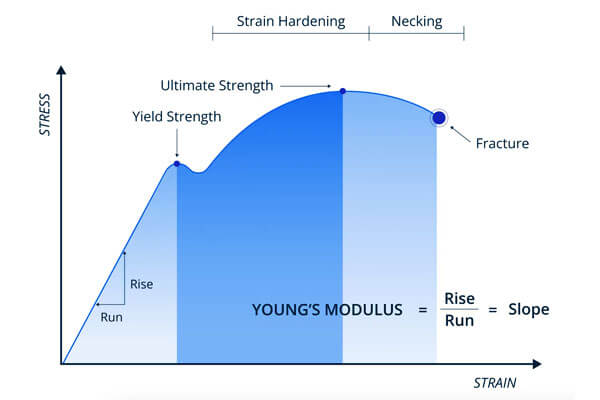
The relationship between stress and strain is commonly illustrated by the stress–strain curve, which characterizes different stages of mechanical behavior.
Elastic vs. Plastic Deformation
- Elastic deformation is reversible. According to Hooke’s Law, stress is proportional to strain up to the elastic limit.
- Plastic deformation, however, is permanent. Once the material surpasses its yield strength, it undergoes irreversible changes in structure.
Key Points on the Stress–Strain Curve:
| Parameter | Description |
|---|---|
| Yield Point | The stress level beyond which plastic deformation begins |
| Ultimate Tensile Strength (UTS) | The maximum stress the material can withstand while being stretched |
| Fracture Point | The point at which the material ultimately breaks or fails |
For example, mild steel typically exhibits a distinct yield point and UTS of around 370 MPa and 450 MPa, respectively, before fracturing at a slightly lower stress after necking.
Material Properties Governing Failure
The failure behavior of a material is not governed by stress-strain behavior alone.
Intrinsic material properties also play pivotal roles, especially in determining how a material absorbs and redistributes stress.
Toughness, Ductility, and Hardness
- Toughness is the material’s ability to absorb energy before fracturing—often visualized as the area under the stress–strain curve.
- Ductility defines the extent to which a material can plastically deform before failure, typically measured by elongation or reduction in area.
- Hardness reflects a material’s resistance to localized plastic deformation, although high hardness can sometimes correlate with brittleness.
Microstructural Factors
At the microscopic level, several internal features influence mechanical failure:
- Grain size: Finer grains often enhance both strength and toughness due to grain boundary strengthening (Hall–Petch effect).
- Inclusions: Non-metallic particles or contaminants can act as stress risers and initiate cracks.
- Second-phase particles: In multi-phase alloys (e.g., steels or titanium alloys), the distribution and cohesion between phases affect how cracks initiate and propagate.
As an example, aluminum alloys with smaller grain sizes and fewer inclusions can achieve fracture toughness values above 30 MPa√m, making them suitable for aerospace skins.
4. Fracture Mechanics Essentials
While classical strength of materials focuses on stress and strain in defect-free structures, fracture mechanics bridges the gap between idealized theory and real-world failures.
It explicitly considers the presence of cracks or flaws, recognizing that most materials contain imperfections that can grow under service conditions.
Fracture mechanics enables engineers to predict when a crack will grow uncontrollably—leading to sudden failure—and to design against such outcomes.
This field is especially vital in safety-critical sectors like aerospace, pressure vessels, and nuclear energy.
Modes of Fracture
Cracks can propagate in several ways depending on the type and direction of the applied load. Fracture mechanics classifies these into three fundamental modes:
- Mode I (Opening Mode): Crack faces are pulled apart perpendicular to the crack plane. This is the most common and most critical mode in engineering applications.
- Mode II (Sliding Mode): In-plane shear where crack surfaces slide over one another parallel to the front.
- Mode III (Tearing Mode): Out-of-plane shear, where crack surfaces move in a tearing or scissoring motion.
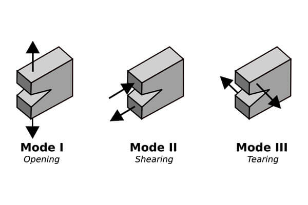
In real-world scenarios, cracks often experience mixed-mode loading, combining two or more of these fundamental modes.
Fracture Toughness: K₁ and K₁c
To quantify a material’s resistance to crack propagation under Mode I loading, fracture mechanics uses the Stress Intensity Factor (K):
- K₁: Describes the intensity of the stress field at the crack tip.
- K₁c (Fracture Toughness): The critical value of K₁ at which rapid fracture occurs.
The fracture condition is reached when:
K1≥K₁c
Fracture toughness values vary significantly by material:
- Aluminum alloys: K₁c ≈ 25–35 MPa√m
- High-strength steels: K₁c ≈ 50–100 MPa√m
- Ceramics: K₁c < 5 MPa√m (high strength but brittle)
The higher the K₁c, the more resistant the material is to crack growth.
This parameter is especially important for components under tensile or impact loading, such as aircraft skins or pressure vessels.
Energy-Based Criteria: Griffith’s Theory
In addition to stress analysis, fracture can also be interpreted through energy concepts.
The Griffith criterion, originally developed for brittle materials, states that a crack will propagate when the energy released from extending the crack exceeds the energy required to create new surfaces.
Griffith’s condition for crack propagation is:
G≥Gc
Where:
- G is the strain energy release rate
- G_c is the critical energy release rate, or the material’s fracture toughness in energy terms (often denoted as GIcG_{Ic}GIc for Mode I)
This criterion becomes particularly useful for understanding fracture in composites, ceramics, and polymers, where surface energy considerations dominate.
Crack Tip Plasticity: LEFM vs. EPFM
Fracture mechanics is often divided into two main branches depending on how much plastic deformation occurs near the crack tip:
- Linear Elastic Fracture Mechanics (LEFM): Assumes small-scale plasticity; applicable to brittle or high-strength materials.
- Elastic-Plastic Fracture Mechanics (EPFM): Used when the plastic zone is significant, often involving the J-integral as a measure of fracture resistance.
For example:
- Brittle materials like glass → LEFM applies
- Ductile metals under high loads → EPFM preferred
According to ASTM E1820, the J-integral method provides a reliable measure of fracture resistance for materials where K₁c cannot be accurately used due to non-linear behavior.
Crack Growth and Stability
Understanding crack behavior isn’t just about initiation—it also involves crack propagation and stability:
- Stable crack growth: Crack advances slowly under increasing load; typical in ductile fracture.
- Unstable crack growth: Sudden, catastrophic fracture with little warning; characteristic of brittle materials.
Engineers often use R-curves (Resistance curves) to plot crack growth resistance versus crack extension, which helps in damage tolerance assessment.
5. Types of Fracture and Failure Modes
Material failure does not occur in a singular fashion.
Instead, it manifests through various fracture mechanisms and failure modes, each influenced by material composition, loading conditions, service environment, and time.
Understanding these failure modes is critical for engineers to select the right materials, design robust structures, and implement proactive maintenance strategies.
Below is a breakdown of the most significant fracture and failure types encountered in engineering applications:
Brittle Fracture
Brittle fracture occurs with little or no plastic deformation and propagates rapidly once initiated. It is often catastrophic and gives minimal warning.
- Mechanism: Typically involves cleavage along crystallographic planes.
- Temperature Sensitivity: Common in body-centered cubic (BCC) metals like low-carbon steel at sub-zero temperatures.
- Fracture Surface: Flat, granular, and may display river patterns or chevrons pointing toward the origin.
- Example: The 1940s Liberty Ships experienced brittle fractures due to low-temperature service and poor weld toughness.
Fracture toughness (K₁c) in brittle materials can be as low as 1–5 MPa√m, making them highly susceptible to crack propagation.
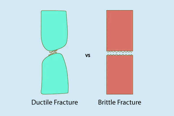
Ductile Fracture
Ductile fracture involves significant plastic deformation prior to failure and absorbs more energy than brittle fracture, making it generally more desirable from a safety standpoint.
- Stages: Initiation (void nucleation), growth (microvoid coalescence), and final fracture (shear lip formation).
- Fracture Surface: Dimpled appearance under scanning electron microscopy (SEM).
- Typical Materials: Aluminum alloys, structural steels, copper.
- Benefits: Provides warning signs before failure, such as necking.
For example, AISI 1018 steel demonstrates over 20% elongation before fracture, indicating a high degree of ductility.
Fatigue Fracture
Fatigue failure accounts for over 80% of in-service failures in metallic components subjected to cyclic loading.
- Stages: Crack initiation → Crack propagation → Final fracture.
- Key Parameters:
-
- S–N Curves: Show the relationship between stress amplitude (S) and the number of cycles to failure (N).
- Surface Features: Beach marks and striations that reveal the history of crack growth.
Example: Aircraft wing spars experience fatigue failure due to cyclic aerodynamic loading, requiring meticulous inspection routines.
Creep Rupture
Creep is time-dependent deformation under constant load at elevated temperatures, eventually leading to creep rupture.
- Typical Materials: Metals at >0.4 Tm (where Tm = melting temperature), such as nickel-based superalloys in turbines.
- Stages:
-
- Primary (decreasing strain rate)
- Secondary (steady-state creep)
- Tertiary (accelerated creep leading to rupture)
- Creep Life Prediction: Often based on Larson–Miller Parameter (LMP) or Norton–Bailey Law.
Example: Jet engine turbine blades made of Inconel alloys resist creep up to 1000°C, with stress rupture times exceeding 10,000 hours under service loads.
Environmental Cracking
Environmentally assisted cracking (EAC) involves fracture induced or accelerated by environmental interactions.
Stress-Corrosion Cracking (SCC):
- Occurs in susceptible alloys under tensile stress and a specific corrosive environment (e.g., chloride-induced SCC in stainless steel).
- Often intergranular in nature.
Hydrogen Embrittlement:
- Hydrogen atoms diffuse into metals, reducing ductility and causing premature fracture.
- Critical in high-strength steels and titanium alloys.
For example, high-strength steels (>1200 MPa UTS) are particularly prone to hydrogen-induced cracking in marine and subsea environments.
Impact Fracture
Impact loading introduces high strain rates, which can significantly alter a material’s failure mode, often driving it from ductile to brittle behavior.
- Testing Methods:
-
- Charpy V-Notch Test (ASTM E23)
- Izod Impact Test
- Measured Quantity: Impact energy absorbed before fracture (Joules).
- Ductile-to-Brittle Transition Temperature (DBTT) is a key metric for materials like carbon steel.
Example: Charpy impact tests reveal that mild steel absorbs over 200 J at room temperature but drops below 20 J at -40°C, indicating a sharp ductile-to-brittle transition.
Summary Table: Major Fracture Types
| Failure Mode | Deformation | Speed | Surface Appearance | Example Materials | Key Concerns |
|---|---|---|---|---|---|
| Brittle Fracture | Minimal | Fast | Cleavage, flat | Cast iron, BCC steels | Sudden failure, low energy |
| Ductile Fracture | Significant | Slow | Dimples, shear lips | Aluminum, low-carbon steel | Warning signs, more energy |
| Fatigue Fracture | Cyclic load | Progressive | Striations, beach marks | All metals under stress | Often invisible until failure |
| Creep Rupture | Time-based | Slow | Necking, grain boundary cavitation | Nickel alloys, stainless steels | Long-term performance at high temp |
| Environmental Cracking | Variable | Varies | Intergranular or transgranular | Stainless steel, titanium | Requires specific environment |
| Impact Fracture | Dynamic | Instant | Jagged or brittle features | Structural steels | Temperature-sensitive behavior |
6. Practical Implications for Design
Understanding fracture behavior is only the beginning; the next step is to apply this knowledge to real-world engineering design.
Whether crafting an aircraft fuselage, a medical implant, or a bridge girder, design engineers must anticipate fracture risks and mitigate failure through smart engineering strategies.
This section outlines the key practical considerations used to ensure structural integrity throughout a component’s service life.
Safety Factors and Redundancy
In safety-critical applications, failure is not an option.
Engineers use safety factors—typically between 1.5 and 4 for ductile metals and higher for brittle materials—to account for uncertainties in material behavior, loading conditions, and manufacturing imperfections.
Moreover, designers introduce redundancy into systems. For example:
- Aircraft use multiple load paths to ensure that if one component fails, others can carry the load.
- Bridges are designed with fail-safe joints that prevent cascading failures.
According to ASME and NASA standards, safety-critical aerospace components often require damage tolerance certification,
proving that a structure can sustain a crack of a given size for a specific number of cycles before failure.
Geometry and Stress Concentrations
Cracks rarely form in uniformly stressed regions. Instead, they initiate at stress concentrators—sharp corners, holes, weld toes, or thread roots—where local stresses can exceed the average by a factor of 2 to 5.
To mitigate this:
- Fillets are added at internal corners.
- Keyhole cuts are used to blunt crack tips.
- Tapered transitions are employed to reduce abrupt changes in cross-section.
As an example, modifying a 90° internal corner with a 5 mm radius fillet can reduce peak stress by up to 60%, dramatically increasing fatigue life.
Material Selection
Selecting a material is not just about strength—it involves a careful balance of:
- Toughness (resistance to crack propagation)
- Corrosion resistance (especially in marine or biomedical environments)
- Density (for weight-sensitive designs)
- Fatigue performance
For instance:
- Titanium alloys offer excellent toughness and corrosion resistance, ideal for implants and aerospace parts.
- High-strength steels provide superior fatigue resistance but may require surface treatments to suppress crack initiation.
According to ASTM testing, the fracture toughness of titanium alloys such as Ti‑6Al‑4V can exceed 55 MPa√m, making them a preferred choice where damage tolerance is critical.
Lifecycle Considerations and Inspection
Designing for durability also involves anticipating how cracks might initiate and grow over time. This approach, known as damage-tolerant design, includes:
- Scheduled inspections based on predicted crack growth rates
- Non-destructive evaluation (NDE) methods such as ultrasonic or X-ray testing
- Replaceable wear components that can be easily monitored and swapped out
In aerospace, Boeing 787 composite panels are routinely inspected using phased array ultrasonics to detect subsurface cracks invisible to the naked eye.
This proactive maintenance extends component life while ensuring safety.
Surface Engineering and Residual Stresses
Surface condition plays a significant role in crack initiation. Rough surfaces, machining marks, or corrosion pits often become initiation points under cyclic loading.
To enhance fracture resistance:
- Shot peening introduces compressive residual stresses that slow crack growth.
- Coatings like anodizing or PVD improve corrosion resistance and reduce surface flaws.
- Polishing or burnishing smoothens surfaces, increasing fatigue life by 25–50%.
For example, automotive suspension springs that undergo shot peening exhibit up to 200% improvement in fatigue resistance, according to SAE J2441 standards.
7. Experimental Characterization
While theoretical models and simulations provide invaluable insights, the true understanding of fracture behavior begins with physical testing.
Experimental characterization validates assumptions, calibrates predictive models, and ensures that materials and components meet safety and performance standards under real-world loading conditions.
This section presents the most critical methods for characterizing fractures, highlighting both standardized procedures and their practical significance across industries.
Tensile and Compressive Testing
At the foundation of material failure analysis lies tensile and compressive testing. These tests reveal how materials respond to uniaxial loading, defining key mechanical properties such as:
- Yield Strength (σ<sub>y</sub>)
- Ultimate Tensile Strength (UTS)
- Young’s Modulus (E)
- Elongation at Break
Standardized by ASTM E8/E8M, tensile testing typically uses dog-bone-shaped specimens pulled at a constant strain rate until fracture.
For instance, a structural steel like ASTM A36 may show a UTS of ~400–550 MPa and elongation of 20–25%.
In compressive testing—especially critical for brittle materials such as ceramics or cast irons—samples are compressed to identify buckling limits and compressive strength,
typically conducted under ASTM E9 standards.
Fracture Toughness Testing
To understand how a crack behaves under stress, engineers perform fracture toughness testing, often using pre-cracked specimens subjected to controlled loading.
- ASTM E399 defines the plane-strain fracture toughness test, yielding the critical stress intensity factor (K<sub>IC</sub>).
- For ductile materials, the J-integral method (ASTM E1820) accounts for non-linear energy dissipation during crack growth.
For example, aerospace-grade aluminum alloy 7075-T6 exhibits a K<sub>IC</sub> of ~25–30 MPa·√m, while certain ultra-tough steels can exceed 100 MPa·√m.
These values directly feed into damage-tolerant design calculations, determining allowable flaw sizes and inspection intervals.
Fatigue Testing
Since 90% of mechanical failures occur due to fatigue, this testing method is essential. Fatigue testing exposes materials to cyclic loading to determine:
- Endurance limit (S<sub>e</sub>)
- Fatigue life (N<sub>f</sub>)
- Crack propagation rate (da/dN)
Methods include:
- Rotating bending tests
- Axial fatigue (tension–compression)
- Dwell fatigue for creep–fatigue interaction
S–N curves (stress vs. cycles) reveal how long a material can survive under repeated stress.
For steels like AISI 1045, the fatigue limit is approximately 0.5 × UTS, or about 250 MPa for typical strengths.
Paris’ Law (da/dN = C(ΔK)<sup>m</sup>) helps predict the rate of crack growth in the stable propagation phase—especially important in aerospace and nuclear components.
Impact and Bend Testing
Impact testing quantifies how materials respond to sudden, high-rate loading, essential in applications like automotive crash safety or structural failure under seismic loads.
- Charpy and Izod impact tests (ASTM E23) measure energy absorbed during fracture, indicating notch toughness.
- Charpy values for ductile steels may reach 80–120 J, whereas brittle ceramics may absorb <10 J.
Three-point bending tests, on the other hand, are used to measure flexural strength and fracture behavior in layered or brittle materials such as composites, polymers, or laminates.
These methods provide insights into fracture initiation under dynamic or multi-axial loading, complementing static tests.
Fractography
To fully diagnose a fracture event, engineers turn to fractography—the detailed examination of fractured surfaces using:
- Optical microscopy for macro-scale crack path analysis
- Scanning Electron Microscopy (SEM) for microstructural features
Fractography reveals:
- Brittle fracture patterns (cleavage, river patterns)
- Ductile features (dimple rupture from void coalescence)
- Fatigue striations showing cyclic crack growth
- Secondary damage from corrosion or overload
Summary Table – Key Experimental Techniques in Fracture Analysis
| Test Type | Standard | Purpose | Key Output |
|---|---|---|---|
| Tensile Testing | ASTM E8/E8M | Basic mechanical properties | σ<sub>y</sub>, UTS, elongation |
| Fracture Toughness | ASTM E399, E1820 | Crack resistance | K<sub>IC</sub>, J-integral |
| Fatigue Testing | ASTM E466 | Life under cyclic loads | S–N curve, da/dN |
| Impact Testing | ASTM E23 | Dynamic toughness | Absorbed energy (J) |
| Bending/Flexural Testing | ASTM D790 | Strength in bending | Flexural modulus, strength |
| Fractography | SEM/Optical | Failure diagnostics | Fracture origin, crack propagation |
8. Benefits and Challenges of Fracture Testing
Fracture testing stands as a cornerstone of modern material evaluation and structural integrity assessment.
It offers engineers the empirical basis to predict component behavior under stress, avoid catastrophic failures, and design safer, more reliable products.
However, this vital process is not without technical, logistical, and financial hurdles.
This section explores the dual landscape of fracture testing, highlighting its significant benefits while acknowledging its complex challenges,
especially when translating laboratory data into real-world reliability.
Benefits of Fracture Testing
Enhances Material Selection and Qualification
Fracture testing allows engineers to quantify critical properties such as fracture toughness (K₁c), fatigue life (Nf), and energy absorption.
These metrics guide the selection of materials best suited for high-stakes applications, such as aerospace wing spars, nuclear pressure vessels, or orthopedic implants, where failure is not an option.
For example, ASTM F136 Ti-6Al-4V ELI titanium used in medical implants is routinely tested for fracture toughness to ensure safe load-bearing performance in vivo.
Validates Design Integrity
Fracture tests simulate real-life conditions, revealing how cracks initiate and propagate under various loading scenarios.
Designers can then optimize geometry, reduce stress concentrations, and implement appropriate safety factors.
In critical sectors like aviation, this insight enables damage-tolerant design, which accepts small flaws but prevents them from becoming catastrophic.
Supports Regulatory Compliance
Many industries, from automotive (ISO 26262) to aerospace (FAA, EASA), mandate fracture toughness, fatigue, or impact testing as part of material and component certification.
Meeting these standards assures stakeholders of product reliability and safety.
Improves Predictive Maintenance and Lifecycle Management
Fracture and fatigue data feed into digital twins and predictive maintenance models, helping estimate remaining useful life (RUL) and prevent unplanned downtime.
Data-driven maintenance schedules can extend service life by 10–30%, reducing life-cycle costs while maintaining safety.
Drives Innovation in Materials and Manufacturing
Testing reveals how new alloys, heat treatments, and fabrication methods affect fracture resistance.
It’s an essential step in qualifying advanced materials, such as additively manufactured metals or nano-structured composites, for real-world deployment.
Challenges of Fracture Testing
Despite its utility, fracture testing is resource-intensive and poses multiple limitations that engineers and researchers must manage carefully.
Sample Preparation and Geometric Sensitivity
Preparing standardized test specimens (e.g., compact tension or Charpy bars) requires precise machining and surface finish control.
Any deviation in geometry or surface condition can significantly influence results, especially in fracture toughness and fatigue tests.
Environmental Control and Realism
Fracture behavior often depends on temperature, humidity, and loading rate.
Testing must replicate service conditions—such as elevated temperatures in turbine blades or cryogenic conditions in LNG tanks—to yield meaningful data.
Creep fracture tests, for instance, may require sustained testing for thousands of hours at 600–800°C to simulate real degradation mechanisms.
Scaling from Lab to Full Components
Test coupons often differ in scale, geometry, and constraint conditions from the actual components.
As a result, engineers must apply correction factors or perform full-scale validation, increasing cost and complexity.
Time and Cost Constraints
High-fidelity fracture testing, especially fatigue or creep experiments, can be time-consuming and expensive.
A single fatigue test may run for 10⁶ to 10⁸ cycles, sometimes taking weeks to complete.
In sectors under cost pressure, such as consumer electronics or industrial machinery, extensive fracture testing may not be economically viable for all components.
Interpreting Complex Failure Modes
Fracture behavior is not always straightforward.
Interactions between microstructural features, stress triaxiality, and environmental degradation can produce mixed-mode failures or secondary cracking that complicates diagnosis.
Advanced tools like SEM fractography, X-ray computed tomography, or digital image correlation (DIC) are sometimes required to fully understand the fracture mechanisms, adding further cost and analytical effort.
8. Conclusion
Fracture or breaking point is not merely a material limit—it is a design, safety, and economic concern that demands multidisciplinary attention.
Engineers can effectively manage fracture risks and enhance structural integrity by integrating fundamental mechanics, material science, testing, and predictive modeling.
As materials and monitoring technologies advance, the ability to predict and prevent failures will become even more precise and proactive.

