Shell mold casting occupies a unique niche between conventional sand casting and high‑precision investment or die casting.
By forming a thin, resin‑bonded sand “shell” around a heated pattern, this process delivers tight dimensional tolerances, outstanding surface finish, and excellent reproducibility—all at mid‑to‑high production volumes.
In this expanded analysis, we delve deeper into its technical foundations, historical evolution, industrial economics, environmental footprint, and emerging innovations, supported by quantitative data and smooth transitional insights.
1. Introduction
First developed in the 1940s by German engineer Johannes Croning, shell mold casting emerged to overcome the limitations of loose green‑sand molds.
Today, foundries worldwide pour over 5 million shell mold parts annually, driven by sectors such as automotive, aerospace, pump, and valve manufacturing, that demand tolerances of ±0.3 mm and surface roughness as low as Ra 3.2 µm.
By the end of this article, you’ll appreciate how shell mold casting balances precision, cost, and flexibility to meet the rigorous needs of modern engineering.
2. What Is Shell Mold Casting?
At its core, shell mold casting creates a rigid, pre‑formed mold from thermosetting resin‑coated silica sand.
Unlike green‑sand casting—where sand remains loose—the shell mold’s cured layer withstands metal pressures up to 0.5 MPa without deformation.
Consequently, manufacturers achieve consistent part-to-part repeatability.

Historical Evolution
Croning’s mid‑20th‑century innovation replaced labor‑intensive resin infiltration with oven‑cured shells, reducing cycle times by 30–50% compared to early resin‑bonded processes.
By the 1970s, automated shell‑making machines proliferated, enabling 24/7 production and annual output per line exceeding 100,000 shells.
Importance in Modern Manufacturing
Shell mold casting now accounts for 10–15% of global iron casting volume and 20–25% of precision aluminum castings.
Its ability to handle ferrous and non‑ferrous alloys—ranging from gray iron to A356 aluminum—makes it indispensable for parts where tight fit, minimal machining, and high throughput converge.
3. Process of Shell Mold Casting
The shell mold casting process involves a series of meticulously controlled steps that transform a heated metal pattern and resin-coated sand into a rigid shell mold suitable for high-precision metal casting.
Each stage—from pattern preparation to final metal pouring—plays a critical role in ensuring the dimensional accuracy, surface quality, and mechanical performance of the final product.

Key Steps in Shell Mold Casting
The shell mold casting workflow typically unfolds in six key stages:
1. Pattern Heating
The process begins with the heating of a reusable metal pattern, usually made from iron or steel, to a temperature between 175°C and 370°C.
This temperature range is critical because it activates the thermosetting resin in the coated sand, allowing it to bond and form a hardened shell upon contact.
2. Sand Coating and Application
Next, resin-coated silica sand—typically bonded with phenolic or furan resin—is dumped or blown onto the hot pattern surface.
The resin softens and partially cures upon contact with the heated metal, allowing the sand to adhere and begin forming a shell.
The sand grain size usually ranges from AFS 50–70, optimized for both flowability and surface finish.
3. Shell Formation: Gelling and Curing
Once coated, the pattern is inverted or vibrated to remove excess sand, leaving a uniform layer, typically 6–13 mm thick.
The partially cured shell then undergoes further thermal curing—either while still on the pattern or in a separate oven—ensuring full cross-linking of the resin matrix.
Typical curing durations range from 2 to 5 minutes, depending on shell thickness and resin type.

4. Mold Removal and Assembly
After curing, the rigid shell is carefully ejected from the pattern. A complete mold typically requires two halves (cope and drag), which are then aligned and clamped or glued together.
If the casting design involves hollow sections, ceramic or resin-bonded sand cores are inserted before final assembly.

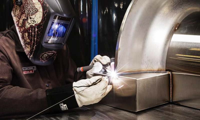
5. Metal Pouring and Cooling
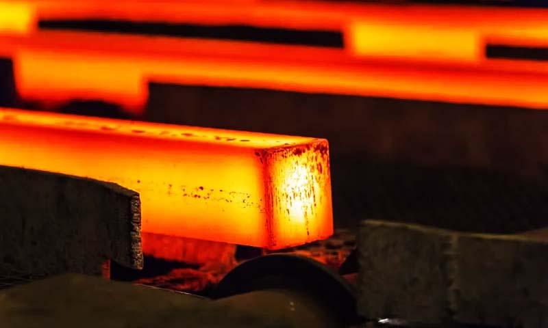
Molten metal—whether carbon steel, ductile iron, aluminum, or copper alloy—is poured into the preheated shell mold through a gating system. Pouring temperatures vary by alloy:
- Steel: ~1,450°C
- Ductile iron: ~1,350°C
- Aluminum alloys: ~700°C
The thin, rigid shell allows for rapid and uniform heat transfer, promoting directional solidification and reducing internal porosity.
6. Shell Removal and Finishing
After cooling, the shell is mechanically broken away using vibration, tumbling, or blasting techniques.
The cast part undergoes gate and riser removal, followed by optional heat treatment, machining, or surface finishing depending on application requirements.
⮕ On automated lines, the full cycle—from shell making to casting removal—can be completed in as little as 5 to 8 minutes, supporting daily outputs of 300–600 parts per mold station.

Equipment and Materials Used
To ensure process consistency and product quality, shell mold casting employs specialized tools and carefully selected materials:
Metal Patterns
- Material: Usually iron or tool steel, sometimes aluminum for smaller parts
- Design: Includes provisions for draft angles (~1–2°), venting, and precise alignment features
- Heating: Electric resistance or gas heating ensures temperature uniformity
Resin-Coated Sand
- Base Sand: High-purity silica (≥ 97% SiO₂), with low thermal expansion
- Resins:
-
- Phenolic: High strength and thermal stability
- Furan: Faster cure and lower emissions
- Epoxy: Used for special alloys or enhanced detail replication
Casting Metals
Shell mold casting supports a broad range of ferrous and non-ferrous alloys:
- Ferrous: Carbon steel, stainless steel, ductile iron, gray iron
- Non-Ferrous: Aluminum (e.g., A356), brass, bronze, copper alloys
Additional Equipment
- Shell mold machines: Automated units for pattern heating, sand deposition, and curing
- Core setters and jigs: Ensure alignment accuracy
- Furnaces: Induction or gas-fired melting units for precise alloy control
- Vibratory knockout stations: Used for post-casting shell removal
4. Materials Science Perspective
The performance of shell mold casting is rooted in materials science.
A deeper understanding of the resin-coated sand system, thermochemical interactions, and solidification behavior of metals in shell molds enables engineers to optimize casting quality, reduce defects, and enhance productivity.
This section explores the intricate interplay between the mold material composition, thermal dynamics, and metal-mold interactions.
Resin-Coated Sand Composition
At the core of shell mold casting lies the resin-coated sand, a composite system designed to exhibit controlled flowability, curing behavior, thermal stability, and mechanical strength.
Base Sand Characteristics
The base sand is typically high-purity silica (SiO₂ ≥ 97%) with a spherical or sub-angular morphology.
The average grain fineness number (AFS) ranges between 50 and 70, which balances permeability and surface finish.
Finer sand improves detail resolution but can reduce gas permeability and increase the risk of defects.
Thermal conductivity of silica sand (~1.2 W/m·K) governs heat transfer during solidification.
Although alternative sands like zircon or chromite offer higher conductivity and refractoriness, they are costlier and reserved for critical applications.
Thermosetting Resin Systems
The coated resin—usually accounting for 2.5–5% of the sand mass—acts as the binding agent during mold formation. Common resin types include:
- Phenolic Resin: Provides high thermal resistance (degradation ≥ 250°C), fast gelling, and good shelf life.
- Furan Resin: Cures at lower temperatures and offers reduced gas evolution.
- Epoxy Resin: Used in specialized casting where extremely smooth surfaces and fine detail replication are essential.
Resin decomposition during metal pouring releases gases (CO, CO₂, H₂), which must be vented to avoid defects like gas porosity and blowholes.

Mold-Metal Interaction and Thermal Chemistry
As molten metal fills the shell, it initiates a sequence of thermochemical events at the mold-metal interface that directly influence casting integrity and surface quality.
Resin Decomposition and Gas Evolution
At temperatures exceeding 500°C, the resin matrix undergoes pyrolytic decomposition, generating gaseous byproducts.
If these gases are not properly vented, they can cause gas entrapment, leading to pinholes, inclusions, or even metal misruns.
To mitigate this, engineers often incorporate venting designs into the mold and use low-emission resins or preheated molds to stabilize gas evolution.
Thermal Shock and Shell Stability
Rapid heat transfer from the molten metal induces thermal gradients that can crack or distort poorly cured shells.
By adjusting preheat temperatures and resin curing cycles, manufacturers can maintain shell rigidity and avoid dimensional warping.
Mold Reactivity and Surface Oxidation
The mold’s chemical stability also affects the final casting surface.
Poor-quality resins or improperly coated sands can chemically react with metal oxides, leading to burn-on or penetration defects.
Using finer sand grains, refractory washes, or coating the mold with alumina reduces this risk.
Metallurgical Impacts and Microstructure Control
Beyond physical shaping, the shell mold environment subtly influences metal microstructure and mechanical properties.
Heat Transfer Rates and Solidification
Shell molds, with their thin walls and moderate thermal mass, offer uniform heat extraction, promoting directional solidification.
This facilitates grain refinement, especially in alloys like carbon steel or aluminum-silicon, enhancing strength and ductility.
Example:
A controlled shell mold environment can reduce grain size in aluminum castings by up to 25% compared to traditional green sand molds, leading to superior mechanical performance.
Surface Finish and Microsegregation
The smooth internal surface of resin-coated shells (surface roughness Ra ≈ 3.2–6.3 µm) minimizes turbulence and oxide inclusion, resulting in a cleaner surface finish.
Additionally, rapid cooling near the mold wall suppresses microsegregation in alloys, improving homogeneity.
Oxidation and Decarburization Control
Ferrous castings in open molds often suffer from oxidation or decarburization during cooling.
The controlled, semi-closed shell mold environment reduces oxygen diffusion, limiting surface degradation and preserving surface carbon content in steels.
5. Advantages of Shell Mold Casting
High-Dimensional Precision
One of the most critical benefits of shell mold casting is its exceptional dimensional accuracy.
The use of a rigid, thermally cured shell ensures that the mold holds its shape throughout the casting process,
resulting in tight dimensional tolerances often within ±0.3 mm, and as fine as ±0.1 mm in optimized scenarios.
This precision reduces the need for secondary machining operations, significantly saving both time and production costs.
Furthermore, the high repeatability of the shell-making process ensures consistency across production batches,
which is crucial for components that require uniformity, such as bearing caps, valve bodies, and gear housings.
Superior Surface Finish
Shell molds offer smoother surface finishes than conventional sand molds due to the use of fine-grained, resin-coated silica sand and high-quality metal patterns.
Typical surface roughness values range between Ra 3.2–6.3 µm, considerably better than green sand casting, which often ranges between Ra 12.5–25 µm.
This improvement in surface finish minimizes the need for surface treatments or polishing, particularly in aerospace and automotive parts, where aesthetics and smooth flow dynamics are essential.
Reduced Machining and Post-Processing
Because of the dimensional stability and fine finish, machining allowances in shell mold cast parts can be reduced by 30% to 50% compared to other sand casting methods.
This not only saves material but also shortens machining cycles and reduces tool wear, leading to lower overall manufacturing costs.
In precision industries, where complex geometries often require intricate finishing, this reduction in machining significantly enhances operational efficiency.
Excellent Repeatability and Automation Compatibility
The shell mold casting process is highly compatible with semi-automated and fully automated systems.
The controlled shell thickness, standardized curing times, and robotic mold handling systems improve production throughput while ensuring consistent quality.
By incorporating programmable logic controllers (PLCs) and robotic arms for shell making and mold assembly, manufacturers can streamline operations, reduce labor dependency, and scale up production economically.
For example, automated lines can produce 100–500 shell molds per hour, depending on part complexity and mold size.
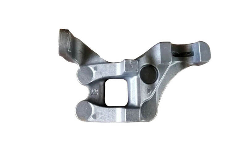
Compatibility with Complex Geometries
Another major advantage of shell mold casting lies in its ability to reproduce intricate shapes and fine details.
The thin shell conforms tightly around complex patterns, allowing for the casting of parts with:
- Sharp corners and fine lettering
- Thin-walled sections
- Intricate internal cavities and bosses
This capability makes it suitable for producing lightweight structural parts without sacrificing mechanical integrity—an essential requirement in aerospace, motorsport, and military applications.
Wide Material Compatibility
Shell mold casting is compatible with a broad range of ferrous and non-ferrous alloys, including:
- Carbon and alloy steels
- Stainless steels (CF8M, 17-4PH, etc.)
- Cast irons (gray, ductile)
- Aluminum and copper-based alloys
This flexibility allows engineers to optimize mechanical and corrosion-resistant properties while maintaining the benefits of high-precision casting.
6. Limitations and Challenges of Shell Mold Casting
Higher Tooling and Setup Costs
Unlike green sand casting, which uses relatively inexpensive wooden or aluminum patterns, shell mold casting requires precision-machined metal patterns—typically made from cast iron or steel.
These patterns must endure repeated thermal cycling and support automation, driving up the initial tooling investment.
For instance, a steel pattern for a mid-sized component may cost 20–50% more than a green sand counterpart.
As a result, shell mold casting is often not cost-effective for low-volume or one-off productions, unless the component’s complexity or surface finish demands outweigh the upfront costs.
Complex Resin and Sand Handling
The core of the shell mold process relies on resin-coated silica sand, which introduces its own set of handling and storage challenges.
The phenolic and epoxy resins used are sensitive to humidity and require controlled storage conditions to maintain quality and performance.
Moreover, the sand mixture must remain consistent in grain size and coating distribution to ensure mold reliability.
During casting, the resin undergoes thermal decomposition, releasing fumes such as formaldehyde and phenol vapors, which must be managed through adequate ventilation and fume extraction systems.
Failure to do so can result in workplace safety hazards and non-compliance with environmental regulations.
Environmental Considerations
As environmental standards grow more stringent, the chemical emissions and waste management requirements associated with shell mold casting have become more pressing.
Unlike green sand, which can be reused many times with minimal treatment, used shell sand is often non-recyclable due to the thermoset resin coating.
Additionally, the thermal decomposition of phenolic resins generates VOCs (volatile organic compounds), necessitating investment in air filtration and pollution control systems.
These systems add complexity and recurring costs, especially for foundries operating in regions with tight environmental controls, such as the EU or parts of North America.
Unsuitability for Very Large Castings
Another significant limitation lies in shell mold fragility.
While the thin shell structure offers precision and finish, it lacks the structural robustness required to contain large volumes of molten metal without reinforcement.
Consequently, very large castings (above 50–100 kg) are rarely produced using this method.
For components such as turbine casings, large engine blocks, or heavy-duty gear housings,
alternative casting processes like green sand casting, investment casting with ceramic shells, or permanent mold casting may offer better scalability and cost-effectiveness.
Sensitivity to Process Control
Finally, shell mold casting demands tight process control to avoid defects such as:
- Shell cracking
- Gas porosity
- Cold shuts or misruns
Inconsistent heating of the metal pattern, poor shell thickness control, or improper sand mixing can lead to casting flaws that may not be easily reworkable.
This sensitivity necessitates skilled operators, regular maintenance, and robust quality assurance protocols.
7. What industries use shell mold casting?
Shell mold casting thrives in sectors requiring precision and moderate volumes:
- Automotive: Transmission housings, brake components, suspension parts—where tolerances of ±0.5 mm and high fatigue resistance drive safety.
- Aerospace & Defense: Turbine housings, landing‑gear parts—where surface finish (Ra ≤ 6 µm) and dimensional fidelity matter.
- General Engineering: Pump casings, gear housings, valve bodies—where leak‑free surfaces and complex channels benefit from shell mold accuracy.
- Marine, Railway, Agriculture: Components facing corrosive environments and variable loads, such as pump impellers and hydraulic housings.
8. Shell Mold Casting vs. Other Casting Techniques
To determine the most effective casting method for a specific application, engineers and procurement teams must weigh precision, complexity, cost, and scalability across multiple technologies.
Shell mold casting stands at the intersection of high-precision and mid-volume production, but how does it compare to other widely used casting processes?
| Criteria | Shell Mold Casting | Green Sand Casting | Investment Casting | Die Casting |
|---|---|---|---|---|
| Dimensional Precision | High (±0.3 mm typical) | Low (±1.0 mm or more) | Very High (±0.1–0.3 mm) | High (±0.1–0.4 mm) |
| Surface Finish (Ra) | Good (3.2–6.3 µm) | Fair (6.3–25 µm) | Excellent (1.6–3.2 µm) | Excellent (0.8–3.2 µm) |
| Part Complexity | Moderate to High | Low to Moderate | Very High | Moderate |
| Suitable Materials | Broad – Ferrous & Non-Ferrous | Broad – Especially Cast Iron | Mostly Non-Ferrous & Superalloys | Primarily Non-Ferrous (Al, Zn, Mg) |
| Mold Type | Disposable Resin-Coated Sand | Disposable Green Sand | Disposable Ceramic Shell | Permanent Steel Die |
| Tooling Cost | High (due to metal pattern) | Low | Moderate (wax + ceramic + tooling) | Very High (complex dies and machines) |
| Initial Equipment Investment | Moderate | Low | Moderate to High | Very High |
| Production Volume Suitability | Medium to High | Low to High | Low to Medium | High |
Cycle Time |
Moderate | Short | Long | Very Short (seconds per part) |
| Automation Compatibility | Moderate to High (PLC, robotics) | Low | Low | Very High |
| Environmental Impact | Moderate (fume emissions from resin, sand waste) | Low (recyclable sand) | High (wax and ceramic waste, energy-intensive) | Moderate to High (cooling fluids, die wear particles) |
| Casting Size Range | Small to Medium parts | Small to Very Large parts | Small to Medium parts | Small to Medium parts |
| Defect Control | Good (dense shell reduces porosity) | Fair (gas and sand inclusions common) | Excellent (near-net shape, low porosity) | Excellent (high pressure limits voids) |
| Cost Efficiency (Med Volume) | Good | Excellent | Fair | Excellent |
9. Economic and Production Considerations
- Tooling Amortization: At 20,000 parts/year, pattern costs drop to $1–3 per part over a 10‑year lifespan.
- Material Costs: Resin‑coated sand runs $3–5/kg, vs. $1–2/kg for uncoated sand; however, labor and machining savings offset this premium.
- Cycle Times: Automated lines achieve 2–3 minutes per shell, translating to a daily throughput of 400–600 parts.
- Break‑Even Volume: Shell mold casting becomes cost‑effective over green sand when volumes exceed 5,000 units annually.
10. Conclusion
Shell mold casting parts deliver tight tolerances, excellent surface quality, and robust mechanical properties at competitive costs.
While it demands higher initial tooling and careful environmental controls, its ability to automate, reproduce complex geometries, and minimize post‑cast machining secures its role in the automotive, aerospace, pumps, and valves industries.
LangHe is the perfect choice for your manufacturing needs if you need high-quality shell mold casting services.