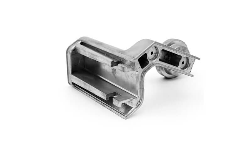
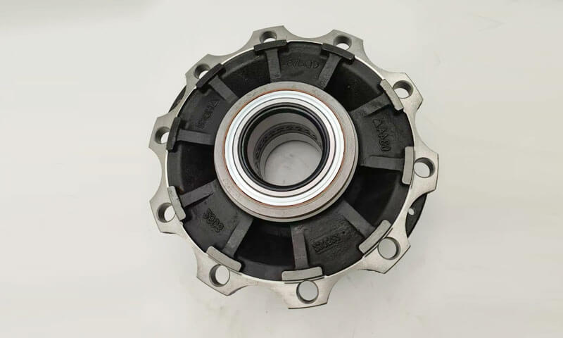
Литі колеса та диски представляють велику категорію обертових структурних компонентів, які широко використовуються в автомобільних гальмівних системах, обладнання механічної трансмісії, гірське обладнання та суднові силові агрегати.
Типові продукти включають маховики, гальмівні диски, ремінні шківи, Колісні вузлики, зубчасті диски та гальмівні барабани.
Усі ці частини мають ідентичні структурні характеристики, як осесиметричні обертові тіла: товстий центральний вузол, що утворює помітні гарячі точки, перехідні сполучні перетинки між втулками та зовнішніми ободами, і тонкостінних зовнішніх окружних країв.
Різка невідповідність товщини стінок створює невід’ємні металургійні проблеми, включаючи усадкову пористість, зосереджену всередині вузлів, торцева деформація короблення, тріщини від термічного напруження, схильність до охолодження на тонких зрізах, нерівномірна окружна твердість, шлакові включення і газові пори.
Основна філософія проектування процесу полягає в регулюванні послідовності затвердіння через стояки, охолодження та оптимізоване розташування литників для реалізації спрямованого або пропорційного затвердіння на вимогу.
Лиття в пісок стало домінуючим способом виробництва коліс середнього та великого розміру & дискове лиття з малими та середніми серійними обсягами виробництва завдяки гнучкому оснащенню, низькі початкові інвестиції та сильна адаптованість до різноманітних геометрій.
1. Структурні характеристики та проблеми лиття деталей колеса та диска
Лиття коліс і дисків є типовими ротаційні структурні компоненти характеризується осесиметричною геометрією, великі відмінності в товщині зрізу, і складна поведінка теплопередачі під час затвердіння.
Хоча ці компоненти зазвичай мають відносно прості зовнішні форми, якість їх внутрішнього лиття сильно залежить від взаємодії між геометрією, потік розплавленого металу, і контроль затвердіння.
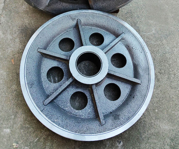
Типові структурні характеристики колісних і дискових відливок
Лиття колеса або диска загалом можна розділити на три функціональні області: концентратор, диск/веб-розділ, і зовнішній край.
З центральний вузол зазвичай є найтовстішою секцією та забезпечує точку з’єднання для валів, підшипники, болти, або системи передачі.
Через великий обсяг і повільну швидкість охолодження, концентратор стає основною термальною точкою під час затвердіння.
Рідкий метал у цій області залишається розплавленим довше, ніж навколишні області, спричиняючи високий ризик дефектів усадки, якщо не буде забезпечено достатнє живлення.
З диск або веб-розділ з'єднує втулку із зовнішнім ободом і відповідає за передачу механічних навантажень, зберігаючи легку конструкцію.
Ця область часто містить поступові або криволінійні переходи товщини. Неправильна конструкція переходу або нерівномірне охолодження можуть спричинити залишкові напруги, спотворення, і гарячі розтріскування.
З зовнішній обід зазвичай має меншу товщину поперечного перерізу та охолоджується швидше, ніж втулка.
Надмірне охолодження цієї зони може призвести до передчасного затвердіння до того, як концентратор завершить подачу, що призводить до внутрішньої пористості та нерівномірних механічних властивостей.
Співвідношення між цими трьома областями визначає загальну поведінку кастингу:
- Втулка, як правило, залишається гарячою і потребує ефективного годування.
- Диск вимагає збалансованого охолодження, щоб запобігти його деформації.
- Ободок вимагає контрольованого затвердіння, щоб уникнути передчасного замерзання.
Отже, успішна конструкція лиття повинна досягати контрольованого теплового градієнта від зовнішніх областей до центральної зони живлення.
Основні проблеми лиття деталей коліс і дисків
Литі колеса та диски мають складну температурну поведінку через їх типову структуру товсті концентратори, тонкі павутини, і зовнішні диски.
Великі відмінності в товщині зрізу створюють нерівномірне затвердіння, труднощі з годуванням, і концентрація стресу.
У наведеній нижче таблиці наведено основні проблеми кастингу та відповідні методи контролю.
| Кастинг виклик | Причина і механізм | Типові дефекти або ризики | Рекомендовані заходи контролю |
| Усадкова пористість у тепловій гарячій точці концентратора | Центральна втулка має найбільшу товщину профілю та найдовший час затвердіння. Оскільки навколишні території замерзають раніше, канали живлення можуть бути заблоковані, запобігання компенсації рідким металом усадки при затвердінні. | Внутрішні усадочні порожнини, мікропористість, знижена втомна міцність, погані результати УЗД. | Застосувати дизайн спрямованої твердості; оптимізувати розмір і розташування стояка; використовувати ізольовані/екзотермічні стояки, зовнішній озноб, і належний контроль температури розливу. |
| Нерівномірне охолодження та утворення термічної напруги | Тонкий обідок і павутинки охолоджуються швидше, в той час як товста втулка залишається гарячою довше. Різні швидкості охолодження створюють температурні градієнти та нерівномірне стиснення. | Гарячі тріщини, залишковий стрес, викривлення диска, втрата округлості, викривлення при обробці, динамічний дисбаланс. | Оптимізуйте орієнтацію лиття, жорсткість форми, умови охолодження, і застосувати термообробку для зняття напруги для точних компонентів. |
Неповне заповнення тонкого диска та веб-розрізів |
Тонкі секції швидко втрачають тепло під час заповнення форми. Якщо температура розплавленого металу знижується нижче критичної температури заповнення, утруднюється повне заповнення порожнини. | Неправильно, Холод закривається, неповні краї, погана якість поверхні. | Оптимізуйте розташування воріт, швидкість наповнення, Температура, і використовуйте плавні системи заповнення з низькою турбулентністю, такі як кільцеподібний боковий затвор або нижнє заповнення. |
| Газова пористість і неметалічні включення | Турбулентний потік розплавленого металу викликає затягування повітря, окислення, змішування шлаку, і ерозія цвілі. Великі обсяги заливки збільшують ризик включення. | Продуви, підповерхнева пористість, оксидні дефекти, шлакові включення, знижена стомлюваність. | Використовуйте ліберні системи з низькою турбулентністю, пінокерамічні фільтри, ефективне видалення шлаків, належна проникність цвілі, і стабільні практики розливу. |
| Спотворення розмірів і нестабільність обробки | Нерівномірне стиснення під час охолодження викликає накопичення внутрішньої напруги. Гаряча втулка обмежує усадку більш холодних секцій обода. | Відхилення площинності, втрата концентричності, позакругові умови, надмірний припуск на обробку. | Покращення симетрії охолодження, оптимізувати дизайн форми, контроль часу витрушування, і проводити лікування для зняття стресу, коли це необхідно. |
2. Загальна схема процесу & Схеми розставання
Схема процесу пісочний кастинг колісні та дискові компоненти є критичним фактором, який визначає поведінку заповнення, послідовність затвердіння, точність розмірів, та остаточна якість кастингу.
На відміну від виливків простої форми, компоненти колеса містять значні відмінності в товщині секцій між центральний вузол, диск/веб, і зовнішній обід, особливо важливим є вибір орієнтації лиття та методу розділення.
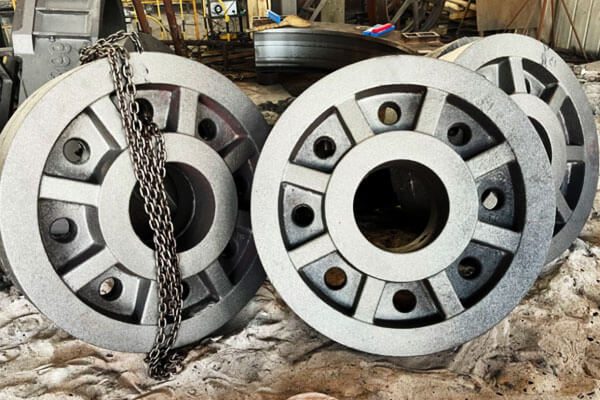
Горизонтальний процес поділу (Найпоширеніше рішення)
Горизонтальна відрізка є найбільш широко використовуваним методом для лиття коліс і дисків, особливо для маховик, гальмівні диски, поліспасти, малі та середні хаби, і загальнопромислові диски.
У такому розташуванні, лиття розташоване горизонтально, а площина розділення зазвичай вибирається через розділ диска або веб-сторінки.
Прес-форма розділена на верхню кришку та нижню опору, дозволяє зручно знімати шаблон, установка сердечника, і складання прес-форми.
Цей метод широко сумісний з обома:
- Системи формування зеленого піску для масового виробництва;
- Пісок на смоляному зв’язку для середньо- та дрібносерійного виробництва.
Основними перевагами горизонтального проділу є його проста технологічна схема, низькі інвестиції в інструменти, і чудова ефективність виробництва.
Розміщення ядра є відносно простим, що робить його придатним для компонентів із центральними отворами, Внутрішні порожнини, або конструкції кріплення валу.
Типові механізми воріт включають:
- Центральний верхній затвор, де розплавлений метал потрапляє через зону втулки та тече назовні до обода;
- Окружний бічний лібер, де розплавлений метал рівномірно надходить по колу, щоб покращити стабільність наповнення.
Однак, горизонтальне формування також має певні обмеження. Тому що верхня і нижня поверхні виливка відчувають різні умови теплопередачі, охолодження часто асиметричне.
Це може призвести до:
- Нерівномірна усадка;
- Деформація торця;
- Залишкова напруга;
- Розмірне відхилення.
На додаток, верхня поверхня порожнини форми має більш високу тенденцію до уловлювання газу та неметалічних включень, які можуть викликати:
- Продуви;
- Шлакові включення;
- Дефекти поверхні.
Отже, для важливих для точності компонентів колеса, Горизонтальний проділ часто вимагає додаткових заходів, таких як поліпшена вентиляція, оптимізоване стробування, і контрольоване охолодження.
Вертикальне розділення та вертикальний процес заливки
Процес вертикального відрізання ставить колесо або диск у вертикальну орієнтацію, з розколом форми вздовж радіального напрямку компонента.
Цей метод в основному використовується для високоточні маточини коліс, важкі ведучі колеса, складові залізниці, і великі обертові частини, що вимагають чудової стабільності розмірів.
У порівнянні з горизонтальним формуванням, вертикальне лиття забезпечує більш симетричне теплове середовище.
Вся окружність виливка відчуває більш рівномірну швидкість охолодження, що значно зменшує різницю температур між різними регіонами.
Основні переваги включають:
- Покращена округлість і концентричність;
- Зменшення деформації після охолодження;
- Більш збалансований розподіл мікроструктури;
- Низька залишкова напруга.
Тому що виливок розташований вертикально, потік розплавленого металу також можна краще контролювати, зменшення ризику нерівномірного заповнення між верхньою та нижньою частинами.
Однак, вертикальне розділення вимагає більш розширеної можливості формування. Основні виклики включають:
- Більш складний малюнок і дизайн серцевини;
- Більш високі вимоги до складання форми;
- Підвищені труднощі в роботі з великими формами;
- Більші вимоги до обладнання для підйому та позиціонування.
Отже, цей метод зазвичай застосовується в середовища виробництва смоли піску, особливо для середнього обсягу або індивідуального важкого лиття, а не для великого автоматизованого виробництва.
Похилий процес заливки (Гібридний метод оптимізації)
Похила заливка - це вдосконалений процес, заснований на принципах горизонтального формування.
Під час заливки, форму нахиляють під контрольованим кутом, Зазвичай навколо 10°–25°, дозволяючи розплавленому металу входити в порожнину в більш стабільних умовах.
Цей метод поєднує в собі переваги горизонтального та вертикального лиття, покращуючи обидва:
- Гладкість заливки;
- Контроль напрямку затвердіння.
Нахилене положення зменшує прямий вплив металу на поверхню форми та зменшує турбулентність під час заповнення.
Одночасно, це сприяє більш сприятливому температурному градієнту, сприяючи подачі розплавленого металу в область втулки.
Похила заливка особливо підходить для:
- Колеса з ковкого чавуну;
- Відливки великих дисків;
- Компоненти з сильною тенденцією до усадки втулки.
Його основні переваги включають:
- Знижене утворення оксидних включень;
- Покращена ефективність подачі концентратора;
- Менший ризик усадкової пористості;
- Краща стабільність розмірів.
Однак, похила заливка вимагає додаткового обладнання або пристосувань для точного контролю кута форми, що робить його більш придатним для спеціалізованого виробництва, а не для стандартних ліній формування.
3. Дизайн піщаної форми та процес виробництва
Якість піщаних форм безпосередньо визначає поведінку наповнення, якість поверхні, точність розмірів, і внутрішньої міцності відливок коліс і дисків.
Оскільки ці компоненти зазвичай поєднуються великі діаметри, товсті концентратори, тонкі веб-секції, і складні умови теплопередачі, процес формування повинен забезпечувати достатню міцність для підтримки стабільності порожнини, а також зберігаючи хорошу проникність і згортання.
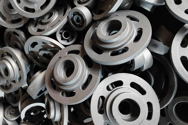
Формування із зеленого піску для масового виробництва малих і середніх компонентів коліс
Формування із зеленого піску є одним із найбільш широко використовуваних і економічних методів виробництва малих і середніх коліс і дисків., наприклад:
- Ремінні шківи;
- Маленькі маховики;
- Гальмівні барабани;
- Диски загальнопромислові.
У цьому процесі використовується суміш кремнеземного піску, Бентонітова глина, вода, і вуглецеві добавки для створення багаторазового формувального матеріалу.
Він особливо підходить для автоматизованих виробничих ліній, де потрібна висока продуктивність і низька вартість виробництва.
Продуктивність зеленого піску сильно залежить від його фізичних властивостей. Типові контрольні параметри включають:
| Параметр | Типовий діапазон | Вплив на якість лиття |
| Вміст вологи | 3.2%–3,8% | Контролює міцність форми, пластичність, і газогенерація |
| компактність | 38%–45% | Визначає щільність формування та стабільність порожнини |
| Проникність | ≥80 | Забезпечує ефективний вихід газу під час заливки |
| Зелена міцність на стиск | 0.12–0,16 МПа | Забезпечує достатню міцність форми проти тиску металу |
Необхідно ретельно контролювати співвідношення активного бентоніту і вуглецевих добавок. Бентоніт забезпечує міцність зв'язку, тоді як вугільний пил або подібні вуглецеві добавки допомагають зменшити:
- Проникнення металу;
- Дефекти вигорання;
- Шорсткість поверхні;
- Поверхневі дефекти, пов'язані з газом.
Під час виробництва, температура регенерованого піску також повинна контролюватися. Гарячий регенерований пісок може негативно вплинути на розподіл вологи та погіршити якість цвілі, призводить до поганої обробки поверхні та нестабільності розмірів.
Для лиття коліс і дисків, Зазвичай застосовуються додаткові вентиляційні заходи, оскільки газ має тенденцію накопичуватися навколо найвищих точок втулки та секцій перетинки.
Типові рішення включають:
- Кільцеві вентиляційні канавки вздовж роздільної поверхні;
- Вентиляційні отвори для газу у верхніх точках форми;
- Додаткові вентиляційні стояки над закритими порожнинами.
Однак, формування із зеленого піску також має обмеження. Оскільки форма має відносно низьку жорсткість і помірну стабільність розмірів, типова точність розмірів приблизно CT9 - CT11 відповідно до стандартів допуску на лиття.
На додаток, відносно повільні та неконтрольовані характеристики охолодження форм із зеленого піску збільшують ризик дефектів усадки в товстих секціях втулки.
Отже, зелений пісок, як правило, не є кращим для важких втулок коліс із ковкого чавуну, які вимагають суворого ультразвукового контролю або високої стійкості до втоми.
Самозатвердіюча піщана смола для лиття великих і високоефективних коліс
Для великих втулок коліс, надпотужні маховики, складові залізниці, і виливки, що вимагають суворого неруйнівного контролю, Самотвердіюча смоляна пісок є кращою технологією формування.
На відміну від зеленого піску, смоляний пісок досягає міцності форми завдяки хімічному зв’язку між смолою та затверджувачем, дозволяє виготовляти великі та складні прес-форми без зовнішнього обладнання для ущільнення.
Типові матеріали включають:
- 70/140 сітчастий кварцевий пісок;
- Керамзитовий пісок для покращеної термостабільності;
- Фуранові смоли або системи лужних фенольних смол.
Співвідношення додавання смоли зазвичай контролюється приблизно в межах 1.0%–1,4%, при цьому дозування затверджувача регулюється відповідно до:
- Температура навколишнього середовища;
- Вологість;
- Необхідна швидкість затвердіння;
- Вимоги до виробничого циклу.
Смоляний пісок забезпечує кілька важливих переваг для лиття коліс і дисків:
Покращена точність розмірів
Висока жорсткість і стабільність смоляно-піщаних форм дозволяє досягти приблизної точності розмірів CT8–CT9, що значно краще, ніж звичайне формування із зеленого піску.
Це особливо важливо для обертових компонентів, на які може вплинути відхилення розмірів:
- Баланс продуктивності;
- Вирівнювання валів;
- Припуск на механічну обробку;
- Термін служби.
Кращі можливості для складних ядер
Виливки великих коліс часто вимагають внутрішніх порожнин, монтажні отвори, або складні вузлові структури. Смоляний пісок дозволяє виробництво:
- Великі вузли сердечника;
- Тонкі і складні піщані керни;
- Акуратні внутрішні проходи.
Це робить його дуже придатним для індивідуального замовлення, цільний, і дрібносерійне виробництво.
Вища якість поверхні
Більш гладка поверхня порожнини форми зменшується:
- Адгезія піску;
- Шорсткість поверхні;
- Навантаження на прибирання;
- Припуск на механічну обробку.
Однак, смоляний пісок також створює певні труднощі.
Тому що смоляні в’яжучі виділяють більше газу під час заливки, неправильний контроль процесу може спричинити:
- Підповерхневі вибухи;
- Газовий пористість;
- Дефекти, пов'язані з вуглецем.
На додаток, Форми зі смоляного піску мають більш високу жорсткість і меншу здатність до згортання порівняно із зеленим піском. Для виливків товстого профілю, обмежене скорочення може збільшити ризик:
- Термічний стрес;
- Гаряче тріск;
- Концентрація залишкових напруг.
Отже, процеси смоляного піску вимагають ретельного узгодження міцності форми, Дизайн стояка, і контроль охолодження.
Технологія покриття прес-форм
Покриття форми відіграє важливу роль у покращенні якості поверхні та запобіганні дефектам лиття, особливо для деталей коліс і дисків з великими гарячими ділянками і складними переходами.
Основне призначення покриттів — створити захисний бар’єр між розплавленим металом і піщаною формою, зменшення:
- Проникнення піску;
- Реакція метал-форма;
- Дефекти вигорання;
- Шорсткість поверхні.
Для різних матеріалів потрібні різні системи покриття.
для відливки коліс із сірого чавуну, Покриття на основі графіту зазвичай застосовуються, оскільки графіт забезпечує:
- Хороша термічна стабільність;
- Знижене проникнення металу;
- Покращена обробка поверхні.
для ковкого чавуну і товстого литва, Цирконові порошкові покриття на спиртовій основі зазвичай є кращими через їх:
- Висока вогнетривкість;
- Відмінна стійкість до ерозії розплавленого чавуну;
- Сильний захист у гарячих точках.
Типова процедура включає:
- Перше нанесення покриття для покриття всієї поверхні порожнини;
- Повне висихання для видалення вологи;
- Друге нанесення покриття для покращеного захисту;
- Остаточна перевірка перед складанням форми.
Недостатнє висихання може утворювати додатковий газ під час заливки, тоді як надмірна товщина покриття може знизити проникність і вплинути на якість лиття.
Конструкція вентиляційної системи для піщаних форм для коліс і дисків
Управління газом є критичним аспектом лиття коліс і дисків, оскільки їхня геометрія обертання природним чином створює зони накопичення газу.
Правильно розроблена вентиляційна система зазвичай включає:
| Захід вентиляції | Типовий дизайн | Функціонування |
| Вентиляційні канавки роздільної поверхні | Кільцеподібні борозенки приблизно 0.4 мм × 6 мм | Забезпечує канали виходу газу вздовж інтерфейсу форми |
| Вентиляційні стрижні маточини | Вентиляційні отвори φ8–12 мм або стрижні у верхній частині втулки | Вивільняє концентрований газ із товстих секцій |
| Система вентиляції ядра | Вентиляційні шнури або пористі канали всередині піщаних ядер | Направляє внутрішні гази ядра за межі форми |
| Витяжні стояки | Розташований у високих точках виливки | Покращує стабільність наповнення та запобігає захопленню газу |
Ефективна конструкція вентиляції повинна підтримувати баланс: недостатня вентиляція викликає дефекти газу, тоді як надмірна вентиляція може послабити форму або збільшити ризик проникнення металу.
4. Конструкція литникових систем для лиття коліс і дисків
Система литників відіграє вирішальну роль у визначенні внутрішньої якості, розмірна стабільність, і механічні характеристики відливок коліс і дисків.
Завдяки типовій обертовій геометрії — з масивною втулкою, відносно тонкі веб-секції, і тонший зовнішній край — процес наповнення необхідно ретельно контролювати, щоб уникнути турбулентності, захоплення оксиду, Холод закривається, неповне заповнення, і нерівномірний розподіл температури.
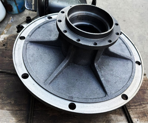
Центральна верхня система воріт: Проста компоновка з потужною здатністю спрямованого затвердіння
Система центрального верхнього литника є одним з традиційних рішень для маховиків і відносно простих дископодібних виливків..
У цьому дизайні, розплавлений метал надходить із зони центральної втулки і тече радіально назовні до обода через перетинчасту частину.
Таке розташування забезпечує природний температурний градієнт, оскільки центральна втулка залишається гарячішою, ніж зовнішній край під час наповнення та затвердіння.
При поєднанні з правильно спроектованими стояками, система може сприяти спрямованому твердінню від тонших зовнішніх секцій до втулки, що дозволяє живити центральну гарячу точку.
Однак, центральне положення годування також створює кілька потенційних проблем.
Постійний вплив високотемпературного розплавленого металу на ділянку втулки збільшує теплову концентрацію втулки, що може збільшити гарячу точку та збільшити ризик усадкових порожнин або мікропористості.
На додаток, прямий вплив струменя металу на центр може спричинити турбулентність на початковій стадії заповнення, збільшення можливості утворення оксидної плівки та винесення шлаку.
Для покращення продуктивності, сучасні конструкції часто включають пінокерамічні фільтри в басейні для виливання, витягніть кілька радіальних входів від центру, і відрегулюйте напрямок потоку, щоб запобігти прямому удару металу по тонких ділянках полотна. Ці модифікації допомагають зменшити турбулентність і покращити внутрішню чистоту.
Система кільцевих щілин: Переважне рішення для гальмівних дисків і точних обертових деталей
Для гальмівних дисків, гальмівні барабани, та інші компоненти, що вимагають відмінної точності розмірів і динамічного балансу, кільцевий щілинний бічний затвор широко вважається одним із найефективніших рішень.
У цій конфігурації, Навколо втулки встановлюється круговий бігунок, з кількома вузькими отворами, рівномірно розподіленими по колу.
Розплавлений метал надходить у порожнину форми одночасно з кількох напрямків, створюючи збалансований малюнок наповнення.
Основною перевагою цієї системи є її здатність досягти рівномірного розподілу температури по всьому колу.
Оскільки розплавлений метал досягає різних ділянок виливка майже одночасно, температурні градієнти зведені до мінімуму, зниження залишкової напруги, спотворення, і відхилення округлості.
Відносно щадне заповнення також зменшує турбулентність порівняно з прямим заливкою зверху. Менша турбулентність означає менше окислення, менше захоплених включень, і покращена якість поверхні.
Це робить дизайн особливо придатним для гальмівних компонентів, де допуск на обробку обмежений, а стабільність розмірів є критичною.
Кільцева система литників також підтримує більш рівномірне затвердіння між втулкою, Інтернет, і зовнішній обід.
При поєднанні з правильно розташованими стояками і ознобами, він може ефективно контролювати дефекти усадки в областях зі значними коливаннями товщини стінок.
Нижня система воріт: Високоякісне заповнення для надміцних втулок коліс
Для великих і важких втулок коліс, ведучі колеса, і високонавантажені промислові компоненти, нижній затвор часто вибирають для досягнення максимально можливої якості наповнення.
У нижній литниковій системі, розплавлений метал надходить з нижньої частини порожнини форми і поступово піднімається вгору.
Металева поверхня залишається відносно стабільною під час наповнення, значно зменшує бризки, Введення повітря, і вторинне окислення.
Основною перевагою цього методу є чудовий контроль потоку. Оскільки розплавлений метал піднімається плавно, а не опускається вертикально, значно зменшується ризик турбулентного потоку та ерозії піску.
Це особливо важливо для великих виливків, де навіть невелика кількість оксидних включень або частинок піску може серйозно вплинути на характеристики втоми..
Однак, нижня начинка також має обмеження. Так як верхні ділянки виливки заповнюються в останню чергу, їх температура може знизитися до повного годування.
Отже, нижні литники необхідно ретельно поєднувати з ефективними стояковими системами, ізоляційні рукави, і зовнішнє охолодження для підтримки адекватного тиску живлення та компенсації усадки в товстих секціях втулки.
Загальні вказівки щодо проектування ефективних систем вентиляції
Незалежно від конкретної конфігурації затвора, під час проектування лиття коліс і дисків слід дотримуватися кількох основних принципів.
Закрита або напівзакрита система литників зазвичай є кращою, оскільки вона зменшує турбулентність і покращує відділення шлаку..
Типове співвідношення поперечних перерізів між литниками, бігун, і ingate приблизно:
Літник : бігун : Як щодо = 1 : 1.2 : 0.8–1
Це співвідношення допомагає підтримувати стабільну швидкість металу, уникаючи надмірної турбулентності.
Горизонтальні канали повинні бути виведені за межі останнього входу, щоб утворити зони збору шлаку, дозволяючи домішкам залишатися подалі від ливарної порожнини.
Керамічні пінопластові фільтри часто встановлюються в систему бігунів для подальшого підвищення чистоти розплаву.
Форма воріт також важлива. Віялоподібні, щілина, або тангенціальні засувки часто використовуються для лиття коліс і дисків, оскільки вони поступово розподіляють розплавлений метал і зменшують прямий вплив на поверхні форми.
Зрештою, найефективніша конструкція воріт – це та, яка досягає гладке заповнення, контрольований тепловий потік, і поступове затвердіння від тонких секцій до джерел живлення.
Шляхом оптимізації зв’язку між стробуванням, стояки, озноб, і геометрія лиття, виробники можуть значно зменшити усадкову пористість, включення, деформація, та інші поширені дефекти лиття коліс і дисків.
5. Проектування системи годівлі: Підйоми і озноб
Система подачі є критичним фактором у визначенні внутрішньої якості відливок коліс і дисків.
Завдяки своїй типовій структурі—великі хаби, тонші павутини, і зовнішні ободи — ці компоненти містять значні відмінності в товщині секцій.
Під час застигання, товста ділянка втулки довше залишається рідкою та відчуває більшу об’ємну усадку, що робить його дуже чутливим до усадочних порожнин і мікропористості.
Конструкція стояка для лиття коліс і дисків
Зона втулки зазвичай є основною ціллю живлення, оскільки вона представляє найбільшу термічну масу в лиття.
Стойки зазвичай розташовують вище або близько до втулки, щоб забезпечити рідкий метал під час кінцевої стадії затвердіння.
для відливки коліс із сірого чавуну (EN-GJL-250, EN-GJL-300), зазвичай застосовується спрямоване затвердіння.
Циліндричні або овальні стояки розміщуються в гарячих точках ступиці, і їх модуль розроблено вище, ніж зона живлення, щоб гарантувати, що стояк замерзне пізніше, ніж лиття.
для відливки коліс із ковкого чавуну (EN-GJS-450-10, EN-GJS-600-3), розширення графіту під час евтектичного затвердіння забезпечує часткову здатність до саможивлення.
Отже, уникають надмірного об’єму стояка. Сучасні конструкції зазвичай поєднують менші ізольовані стояки з холодами, щоб підвищити продуктивність лиття, зберігаючи внутрішню міцність.
Для важких маточин коліс з товстим прорізом, ізольовані стояки або екзотермічні стояки часто використовуються для продовження часу подачі та зменшення дефектів усадки.
Контроль охолодження та затвердіння
Охолодження використовується для прискорення локального охолодження та контролю процесу затвердіння.
Збільшуючи відбір тепла в обраних областях, озноб зменшує розмір гарячих точок і сприяє спрямованому твердінню в бік стояка.
Для лиття коліс і дисків, озноб в основному розміщується навколо:
- Бічні стінки втулки, де відбувається концентрація тепла.
- Області переходу від концентратора до мережі.
- Місцеві товсті зрізи з високим ризиком усадки.
Однак, розміщення охолоджувача має бути ретельно оптимізоване. Надмірне охолодження на тонких ділянках обода може спричинити передчасне затвердіння, що призводить до збоїв, Холод закривається, або нерівномірної твердості.
Отже, Охолодження зазвичай уникають на тонких зрізах, якщо не потрібен спеціальний контроль мікроструктури.
Найефективнішим дизайном годівлі зазвичай є поєднання ізольовані стояки та правильно розташовані охолодження, де охолодження контролює потік тепла, а стояки забезпечують остаточну компенсацію усадки.
Поширені дефекти годівлі та рішення
Неправильний дизайн подачі може призвести до кількох типових дефектів лиття:
| Дефект | Основна причина | Метод оптимізації |
| Усадкова порожнина | Недостатня кількість рідини в гарячих точках вузла | Підвищити ефективність стояка або покращити ізоляцію |
| Мікропористість | Поганий напрямок затвердіння та тиск подачі | Оптимізуйте озноб і температурний градієнт |
| Гаряче тріск | Надмірна термічна напруга між товстими та тонкими зрізами | Збалансуйте швидкість охолодження та покращте схему годування |
| Низький вихід лиття | Негабаритні стояки | Оптимізуйте розмір стояка за допомогою моделювання процесу |
6. Плавлення, Нодуляризація та процес модифікації для виливків коліс із ковкого чавуну
Ковкий чавун широко використовується для важких відливок коліс і дисків, оскільки він забезпечує чудове поєднання міцності, міцність, втома, і показники зносу.
У порівнянні з сірим чавуном, ковкий чавун містить сферичні конкреції графіту, які значно знижують концентрацію напруги та покращують механічні властивості.
Однак, досягнення стабільної якості ковкого чавуну вимагає точного контролю плавлення, лікування магнієм, і процеси щеплення.
Процес плавлення та хімічний контроль
Процес плавлення створює основу для якості ковкого чавуну.
Електричні індукційні печі широко використовуються, оскільки вони забезпечують точний контроль температури та хімічного складу.
Типові марки ковкого чавуну для лиття коліс включають:
- EN-GJS-450-10
- EN-GJS-600-3
Типовий діапазон хімічного складу:
| Елемент | Типовий діапазон (%) | Функціонування |
| Вуглець (C) | 3.5–3,8 | Сприяє формуванню графіту |
| Кремнію (І) | 2.3–2,8 | Покращує графітизацію |
| Марганець (Мн) | ≤0,4 | Зміцнює матрицю |
| Сірка (S) | ≤0,025 | Необхідно перевірити перед лікуванням Mg |
| Фосфор (С) | ≤0,03 | Запобігає крихкості |
| Магній (Мг) | 0.035–0,060 залишок | Утворює сферичний графіт |
Типовий контроль температури:
- Температура натискання: 1500–1550°C
- Температура: 1360–1420°C
Необхідно суворо контролювати вміст сірки та фосфору, оскільки надмірні рівні зменшують утворення вузликів та механічні властивості.
Лікування нодуляризації магнієм
Обробка магнієм є ключовим кроком, який перетворює графіт із пластівців у сферичні конкреції. У найпоширенішому методі використовується магнієво-ферросиліцієвий сплав, доданий до розплавленого заліза.
Під час лікування, магній реагує з сіркою і киснем, створення сильної реакції.
Належний контроль температури обробки, додавання сплаву, і відновлення магнію необхідне для отримання стабільного вузлоподібного графіту.
Погана нодулярізація може призвести до:
- Вермикулярне утворення графіту.
- Знижена міцність на розрив і подовження.
- Нижча стійкість до втоми.
Конструкція з високоякісного ковкого чавуну повинна мати:
- Висока вузлуватість графіту.
- Рівномірний розподіл графіту.
- Контрольований розмір вузликів.
- Відповідна феритна/перлітна матриця відповідно до вимог до продуктивності.
Інокуляція та очищення графіту
Інокуляція покращує зародження графіту та стабілізує кінцеву мікроструктуру. Зазвичай він виконується в два етапи: початкове інокуляція під час відведення та вторинне щеплення під час заливки.
Інокулянти на основі феросиліцію, що містять кальцій, барій, або цирконій зазвичай використовуються.
Ефективне щеплення допомагає:
- Збільшити кількість вузликів графіту.
- Зменшити утворення карбіду.
- Поліпшити механічні властивості.
- Домогтися рівномірного розподілу твердості.
Для великих відливів коліс, інокуляція особливо важлива, оскільки повільне охолодження в піщаних формах може призвести до грубого графіту та зниження міцності.
7. Промайдування, Процес охолодження та термічної обробки
Витряска, охолодження, і стадії термічної обробки відіграють важливу роль у збереженні точності розмірів, механічні властивості, і надійність тривалої служби колісних і дискових відливок.
Хоча процес лиття завершується після застигання, неправильне поводження під час охолодження або передчасне видалення з форми може призвести до залишкової напруги, спотворення, і навіть розтріскування, особливо в компонентах з великим діаметром, нерівномірна товщина стінок, і суворі вимоги до балансу.
Контроль часу витримки та витримки
Після заливки і застигання, виливки повинні залишатися всередині піщаної форми протягом достатнього часу перед витряхуванням.
Піщана форма забезпечує теплоізоляцію та дозволяє відливці поступово охолоджуватися, зменшення градієнтів температури між товстими та тонкими зрізами.
Передчасне витрушування знімає цей тепловий захист занадто рано, викликаючи нерівномірне охолодження та збільшуючи ризик:
- Деформація втулки, спричинена залишковою термічною напругою.
- Викривлення полотна та втрата рівності.
- Розтріскування поверхні в зонах високого напруження.
Необхідний час витримки залежить головним чином від розміру відливки, Товщина стіни, Тип матеріалу, і характеристики цвілі.
Типовий час витримки::
| Тип лиття | Рекомендований час витримки |
| Невеликі відливки коліс і дисків | ≥ 30 хвилини |
| Маточини та маховики середніх коліс | 60– 90 хвилин |
| Великі та надміцні колеса | 90–120 хвилин або більше |
Для великих коліс із ковкого чавуну, тривале охолодження всередині форми часто є кращим, оскільки повільне охолодження допомагає зменшити температурні градієнти та покращує стабільність розмірів.
Після витряски, з виливками слід поводитися обережно. Великі литі колеса та диски не можна складати або розміщувати під нерівною опорою, оскільки їх власна вага може спричинити постійну деформацію вигину, поки метал все ще перебуває при високій температурі.
Контрольоване охолодження після струшування
Після вилучення з форми, виливки коліс і дисків повинні продовжувати охолоджуватися в контрольованих умовах.
Швидке охолодження, особливо для деталей із ковкого чавуну великого перетину, може спричинити надмірну термічну напругу між втулкою та ободом.
Правильна практика охолодження включає:
- Уникайте примусового охолодження водою або сильними потоками повітря.
- Дозволяє природним чином охолоджувати виливки в контрольованому середовищі.
- Рівномірна підтримка виливків для запобігання гравітаційним викривленням.
Для коліс з ковкого чавуну, контрольоване охолодження також впливає на кінцеву мікроструктуру.
Повільне охолодження сприяє зростанню графіту та зменшує утворення небажаних карбідів, в той час як надмірні швидкості охолодження можуть збільшити твердість і знизити в'язкість.
Теплова обробка для зняття стресу
Залишкова напруга створюється під час лиття, оскільки різні секції стискаються з різною швидкістю під час охолодження.
Товста втулка, тонка павутина, і зовнішній обідок зазнають різного термічного скорочення, що призводить до внутрішньої напруги, навіть якщо немає видимих дефектів.
Для високоточних деталей коліс, особливо гальмівні диски, ведучі колеса, і великі концентратори, відпал для зняття напруги зазвичай виконується перед механічною обробкою.
Типовий процес зняття стресу передбачає:
- Температура нагріву: 500–550°C
- Час витримки: визначається товщиною і вагою відливки
- Контрольоване охолодження печі для мінімізації нових теплових навантажень
Така обробка зменшує залишкову напругу та покращує стабільність обробки. Без зняття стресу, виливки можуть деформуватися під час чорнової або чистової обробки, оскільки видалення матеріалу звільняє внутрішню напругу.
8. Висновок
Лиття в пісок компонентів колеса та диска є вузькоспеціалізованим процесом, який вимагає ретельного узгодження конструкції прес-форми, ліберна технологія, стратегія годування, металургія, і контроль охолодження.
Ключ до виробництва високоякісних відливок коліс полягає не просто в досягненні повного заповнення, але контролює весь процес термічного потоку та рідини:
- Вибір правильної орієнтації лиття;
- Проектування стабільних і чистих систем наповнення;
- Управління тепловими гарячими точками концентратора;
- Застосування ефективних стояків і холодів;
- Керування металургією ковкого чавуну;
- Використання оптимізації на основі моделювання.
З належним чином розробленим процесом лиття в пісок, виробники можуть виготовляти великі та складні литі колеса та диски з чудовими механічними властивостями, точність розмірів, і довгострокову надійність служби для вимогливих промислових застосувань.
LangHe – професійний виробник коліс і дисків у Китаї
LangHe - професіонал Китайський виробник, що спеціалізується на нестандартних литтях коліс і дисків, надання високоякісних рішень для лиття промислових обертових компонентів, включаючи маховики, гальмівні диски, Колісні вузлики, шківи, зубчасті диски, гальмівні барабани, і частини важкої техніки.
Має великий досвід у технологіях лиття в пісок і смолу, LangHe підтримує клієнтів від початкового проектування лиття та оптимізації процесу до виробництва, обробка, огляд, і остаточна доставка.
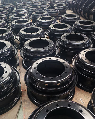
LangHe виробляє литі колеса та диски з широкого діапазону матеріалів, включаючи сірий чавун, пластичне залізо, вуглецева сталь, Лепка сталь, і нержавіюча сталь, відповідність вимогам автомобілебудування, промислове обладнання, енергія, транспортування, і застосування важкої техніки.
Завдяки суворому контролю якості, розширені виробничі можливості, та індивідуальна інженерна підтримка, LangHe забезпечує довговічність, економічний, і індивідуальні рішення для лиття для клієнтів у всьому світі.
Як довірений виробник лиття коліс і дисків у Китаї, LangHe прагне допомогти клієнтам у всьому світі досягти вищої надійності продукції, оптимізована продуктивність лиття, і зниження виробничих витрат завдяки професійному досвіду лиття та постійному інноваційному процесу.
Зв’яжіться з нами, щоб отримати індивідуальне точне лиття.