Introduction
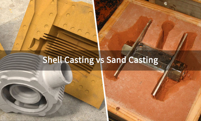
Shell Molding vs Sand Casting—two processes built on the same principle of shaping molten metal with sand, yet delivering very different results.
Sand casting, the age-old workhorse, is prized for its versatility and ability to produce massive components at low cost.
Shell molding casting, a mid-20th-century refinement, takes the same foundation but adds precision, smoother finishes, and consistency that sand casting often struggles to match.
In today’s manufacturing landscape, choosing between the two is more than a technical decision—it’s a balance of accuracy, economics, and application demands.
This article explores their process fundamentals, dimensional accuracy, surface quality, cost structures, environmental impact, and industrial applications.
1. Process Fundamentals: How Shell Molding and Sand Casting Work
To truly appreciate the differences between shell molding vs sand casting, it is essential to examine how each process forms molds, handles molten metal, and extracts finished parts.
While both rely on sand as a refractory material, their mold-building methods—thin, resin-hardened shells versus bulk-packed sand—create very different outcomes in accuracy, efficiency, and scale.
What Is Shell Molding Casting?
Invented in the 1940s, shell molding casting is essentially a precision version of sand casting.
It uses fine resin-coated sand that bonds into a thin, strong shell when exposed to a heated metal pattern. Two cured shell halves are joined to form the mold.
The thin shell offers better dimensional accuracy and smoother surfaces, while being easy to break after solidification.

Core Steps:
- Pattern Preparation: A metal pattern (typically aluminum, steel, or cast iron) is heated to 180–250°C.
Unlike sand casting patterns, shell molding patterns are often single-sided (to form one half of the mold) and feature precision machining to ensure fine detail replication. - Sand Coating: The heated pattern is dipped, sprayed, or placed in a bed of resin-coated sand (silica sand mixed with 2–5% thermoset resin, e.g., phenolic resin, and a catalyst).
The resin melts on contact with the hot pattern, bonding sand grains to form a thin shell. - Shell Formation: The pattern is rotated or shaken to remove excess unbonded sand, leaving a uniform shell (3–10 mm thick) adhering to the pattern.
The shell is cured for 30–120 seconds (via the pattern’s heat) until the resin crosslinks, hardening the shell. - Mold Assembly: Two cured shells (one for the upper “cope” and one for the lower “drag”) are clamped together. Internal cavities (e.g., holes, passages) are created using pre-formed resin-coated sand cores.
- Pouring: Molten metal (e.g., ductile iron, stainless steel) is poured into the shell cavity via gates.
The thin shell ensures rapid heat transfer, accelerating solidification (1–5 minutes for small parts). - Shell Removal: After solidification, the brittle resin shell is broken apart (via vibration or mechanical shock) to extract the casting.
No extensive shakeout is needed, as the shell crumbles into small fragments.
Defining Feature: Shell mold casting produces a lightweight, dimensionally stable mold with excellent surface detail.
Minimizing bulk sand reduces waste and supports precision manufacturing.
What Is Sand Casting?
The most traditional and versatile method, sand casting, uses a mix of silica sand, clay binders (like bentonite), water, and additives.
The sand is compacted around a reusable pattern to form a mold. After the molten metal is poured and solidifies, the mold is broken to retrieve the casting.
Cores can be added for hollow sections. Sand is often recycled, though it requires energy-intensive reclamation.

Green Sand Casting (Wet Sand Casting)
- Mold Making: Silica sand is mixed with 3–5% clay (binder), 2–4% water, and additives (e.g., coal dust to reduce metal penetration).
This “green sand” is packed around a pattern (wood, metal, or plastic) in a flask (a rigid frame) to form the cope and drag. - Pattern Removal: The pattern is withdrawn from the sand, leaving a cavity. Draft angles (1–3°) are required to prevent sand damage during removal.
- Core Placement: Sand cores (made from resin-bonded sand for strength) are inserted into the cavity to create internal features.
- Pouring: Molten metal (e.g., gray iron, carbon steel) is poured into the mold via a sprue and runner system.
Green sand molds have high permeability, allowing gases to escape during pouring. - Shakeout: After solidification (10–60 minutes for small parts, hours for large parts), the flask is opened, and the casting is extracted by vibrating or blasting the sand away.
Resin Sand Casting (Dry Sand Casting)
A more precise variant where green sand’s clay-water binder is replaced with synthetic resins (e.g., furan resin).
The resin sand is cured with heat or catalysts, creating a harder, more dimensionally stable mold. This reduces sand expansion and improves surface finish but increases cost.
Defining Feature: Bulk sand molds give unmatched flexibility in part size—from small brackets to ship propellers weighing hundreds of tons.
However, the softer mold walls and thermal expansion make sand casting less precise than shell mold casting.
2. Mold Properties: Strength, Surface Finish, and Permeability
The mold’s material and structure directly impact casting quality. Shell molding vs sand casting differ significantly in strength, surface finish, dimensional accuracy, and permeability.

Mold Material and Strength
| Property | Shell Molding Casting | Sand Casting (Green Sand) | Sand Casting (Resin Sand / No-bake) |
| Binder Type | Thermoset resin (phenolic) | Clay + water | Synthetic resin (furan, phenolic) |
| Mold Thickness | 3–10 mm (thin, rigid shell) | 50–200 mm (bulk sand) | 50–200 mm (bulk sand) |
| Compressive Strength | 2–5 MPa | 0.1–0.3 MPa | 1–2 MPa |
| Thermal Stability | Up to 1,500°C | Deforms >1,200°C | Up to 1,400°C |
- Shell Molding Casting: High-strength resin shell prevents collapse even under high-pressure metal injection. Minimal thermal expansion ensures dimensional stability.
- Green Sand Casting: Low strength requires careful handling; sand expansion may cause defects like “scabs” or surface irregularities.
- Resin Sand Casting: Combines moderate rigidity and flexibility, better than green sand, but bulk sand limits ultimate precision.
Surface Finish and Dimensional Accuracy
Surface finish and tolerances are critical for reducing post-casting machining costs:
| Metric | Shell Molding Casting | Sand Casting (Green Sand) | Sand Casting (Resin Sand / No-bake) |
| Surface Roughness (Ra) | 1.6–6.3 µm (smooth, near-net-shape) | 6.3–25 µm (rough, requires machining) | 6.3–12.5 µm (moderate) |
| Dimensional Tolerance (ISO 8062-3) | CT7–CT9 | CT10–CT13 (no-bake: CT9–CT11) | CT9–CT11 |
| Linear Tolerance (small dims) | ±0.25–0.5 mm | ±0.8–3.0 mm (size-dependent) | ±0.3–0.6 mm |
| Minimum Wall Thickness | 3–6 mm | 5–8 mm | 3–5 mm |
| Draft Angle | 0.5–1.5° | 1–3° | 1–2° |
- Shell Molding Casting: The resin shell’s smooth inner surface (replicated from the heated metal pattern) eliminates the need for machining for cosmetic or non-critical surfaces.
Tight tolerances (e.g., ±0.2 mm for a 50 mm part) make it ideal for precision components like gear teeth. - Green Sand Casting: Rough surface finish (due to sand grain size, ~0.1–0.5 mm) and mold flexibility require 1–3 mm of machining allowance on critical surfaces.
- Resin Sand Casting: Improved over green sand but still cannot match shell molding’s precision—resin sand’s grain structure (still ~0.1 mm) limits surface smoothness.
Permeability and Gas Evacuation
Permeability (the ability to allow gases to escape) prevents porosity in castings:
- Shell Molding Casting: Moderate permeability (100–200 perm units) due to resin bonding, which partially seals sand pores.
To mitigate gas entrapment, shell molds include small vent holes and are often poured slowly to allow gas escape. - Green Sand Casting: High permeability (300–500 perm units) from clay-water binder, which creates interconnected pores.
This reduces porosity but can lead to “sand inclusions” (sand particles embedded in the casting) if the mold is not properly compacted. - Resin Sand Casting: Low permeability (50–150 perm units) due to resin bonding, increasing the risk of gas porosity unless vents are carefully designed.
3. Castable Materials and Part Suitability
Shell molding vs sand casting differ significantly in their compatibility with metals, alloys, and part geometries.

Compatible Metals and Alloys
Both processes handle gray/ductile iron, carbon/low-alloy steel, stainless steel, aluminum, copper-base alloys, and more.
Shell’s dry, rigid molds resist erosion with steel/iron; green sand is popular for aluminum due to cost and thermal considerations.
| Metal / Alloy | Shell Molding Casting | Sand Casting (Green / Resin) | Rationale |
| Gray Iron (ASTM A48) | Suitable for small-to-medium parts | Suitable for small to very large parts | Sand casting is preferred for large engine blocks or structural components; shell molding is better for precise, smaller castings. |
| Ductile Iron (ASTM A536) | Ideal for precision parts | Possible, less precise | Shell molding ensures uniform nodule formation and controlled cooling; sand casting works for heavier, thicker parts. |
| Stainless Steel (e.g., CF8M) | Excellent for corrosion-resistant, fine-featured components | Can be cast but with higher contamination risk | Shell molding’s resin shell prevents sand-metal reactions, maintaining alloy integrity; green sand may cause chromium depletion. |
| Carbon Steel (ASTM A216) | Suitable for small-to-medium parts | Preferred for large, thick-walled parts | Bulk sand molds handle heavy steel castings well; shell molding provides better dimensional control for smaller, intricate components. |
| Aluminum (e.g., A356) | Excellent for lightweight, high-precision parts | Common for large castings | Thin-shell molds reduce porosity and improve surface finish, critical for heat-treated aluminum; sand casting allows larger part sizes but with lower precision. |
| Bronze / Copper Alloys | Possible for small, detailed components | Suitable for large castings | Shell molding produces finer detail with better surface finish; sand casting allows larger, simpler parts but may require machining. |
Part Size, Complexity, and Weight
| Parameter | Shell Molding Casting | Sand Casting (Green / Resin) |
| Typical Part Weight | 50 g – 20 kg | 1 kg – 100+ kg |
| Maximum Part Size | ~1 m | ~5 m (limited by flask) |
| Complexity | High (thin walls, intricate details, fine threads) | Moderate (thicker walls, simpler geometries) |
| Minimum Wall Thickness | 2–3 mm | 5–8 mm |
| Undercuts | Possible with split patterns or cores | Difficult, requires complex cores or multiple molds |
- Shell Molding Casting: Excels in producing intricate, thin-walled parts such as automotive gearboxes, valve bodies, turbine components, and small industrial machinery.
Its thin shell molds allow reduced material use and precise replication of fine features. - Sand Casting: Best suited for large, heavy, or thick-walled components like mining truck frames, engine blocks, and industrial housings.
Limited ability to reproduce fine details or thin walls due to sand flow and heat retention constraints.
4. Productivity, Cost, and Economics
The choice between shell molding vs sand casting is heavily influenced by production volume, part size, and cost constraints.
Both processes have distinct advantages depending on whether the priority is speed, precision, or economy.

Productivity and Cycle Time
| Metric | Shell Molding Casting | Sand Casting (Green Sand) | Sand Casting (Resin Sand) |
| Cycle Time per Part | 1–5 min (small parts, automated) | 10–60 min (manual, small parts) | 15–90 min (semi-automated) |
| Parts per Hour | 10–30 (automated line) | 1–5 (manual operation) | 2–8 (semi-automated) |
| Setup Time | 4–8 hours (pattern installation) | 1–2 hours (pattern + flask setup) | 2–4 hours (resin mixing + setup) |
Analysis:
- Shell Mold Casting: Automated processes—robotic dipping, shell curing, and assembly—enable rapid production of small-to-medium parts.
Fast solidification of the thin shell further reduces cycle time, making it ideal for high-volume runs (10,000+ parts/year). - Green Sand Casting: Manual mold preparation, pattern removal, and shakeout limit throughput. Best suited for low-to-medium production volumes (hundreds to a few thousand parts/year).
- Resin Sand Casting: Offers improved dimensional stability over green sand, but slower curing and handling reduce speed. Suitable for medium-volume production (5,000–10,000 parts/year).
Cost: Tooling and Per-Part Economics
| Cost Component | Shell Molding Casting | Sand Casting (Green Sand) | Sand Casting (Resin Sand) |
| Tooling Cost | $10,000–$100,000 (durable metal patterns) | $500–$10,000 (wood/plastic patterns) | $2,000–$20,000 (metal or resin-bonded patterns) |
| Per-Part Cost (1 kg) | $1.50–$3.00 (high-volume advantage) | $3.00–$8.00 (labor-intensive) | $2.50–$5.00 (moderate volume) |
| Material Waste | 5–10% (shell fragments + runners) | 15–25% (bulk sand + runner) | 10–20% (resin sand + runners) |
Analysis:
- Shell Mold Casting: Upfront investment is higher due to expensive metal patterns, but durability (>100,000 cycles) and automation significantly reduce per-part costs for large production volumes.
Minimal sand waste and high repeatability further enhance economic efficiency. - Green Sand Casting: Low-cost patterns and setup favor small production runs. However, high labor demand, material waste, and longer cycle times raise the cost per part in medium-to-large runs.
- Resin Sand Casting: Offers a balance between tooling cost and per-part efficiency.
Resin-bonded sand provides better surface finish and dimensional control than green sand, but higher material costs limit cost advantages for very high-volume production.
5. Quality and Defect Rates
Casting quality depends on internal porosity, surface integrity, and mechanical property consistency.
Shell molding vs sand casting exhibit notable differences due to mold rigidity, cooling rate, and material interaction.

Porosity and Internal Defects
| Defect Type | Shell Molding Casting | Sand Casting (Green Sand) | Sand Casting (Resin Sand) |
| Porosity (Vol. %) | 1–3% (mainly gas, minimal shrinkage) | 3–8% (gas + shrinkage) | 2–5% (lower shrinkage, some gas) |
| Shrinkage Cavities | Rare (thin shell promotes rapid, uniform cooling) | Common in thick sections (slow cooling) | Less common than green sand (resin sand reduces expansion) |
| Sand Inclusions | Rare (rigid shell prevents loose sand ingress) | Frequent (loose sand may embed) | Occasional (cohesive resin sand minimizes loose particles) |
Analysis:
- Shell Molding Casting: Thin, resin-bonded shells cool rapidly, minimizing shrinkage cavities.
Mold rigidity prevents sand entrapment, and venting design controls gas porosity. Ideal for precision parts where minimal internal defects are critical. - Green Sand Casting: Bulk sand expands and contracts unpredictably during cooling.
Loose sand in the mold cavity increases the risk of inclusions, and thick sections are prone to shrinkage defects. Additional machining or inspection is often needed. - Resin Sand Casting: The cohesive resin sand improves dimensional stability and reduces sand inclusions compared to green sand, but gas porosity can still occur in large or complex sections.
Mechanical Properties
| Property | Shell Molding (Ductile Iron QT500-7) | Sand Casting (Ductile Iron QT500-7) |
| Tensile Strength | 520–550 MPa (consistent) | 480–520 MPa (variable) |
| Elongation | 8–10% (uniform microstructure) | 6–8% (coarser grains, porosity) |
| Hardness (HB) | 180–200 (stable) | 170–190 (variable) |
Analysis:
- Shell Molding Casting: Rapid cooling through the thin shell produces a fine, uniform microstructure, enhancing tensile strength, hardness, and ductility.
Consistency in mechanical properties makes it suitable for safety-critical components like automotive suspension or aerospace parts. - Sand Casting: Slower, bulk cooling promotes coarser grains and uneven solidification, leading to variability in strength and elongation.
Parts often require post-casting inspection and selective machining to meet specifications. - Resin Sand Casting: Mechanical properties are more uniform than green sand casting, but slower heat dissipation in larger sections can still produce variability in grain size and localized porosity.
Key Takeaways
- Shell Mold Casting: Optimal for precision, high-strength, and low-defect components. Rapid cooling and rigid molds ensure minimal porosity and consistent mechanical properties.
- Green Sand Casting: Best for large, simple parts where absolute precision is less critical. Higher defect rates and variable properties necessitate inspection and machining.
- Resin Sand Casting: A middle ground, offering improved surface finish and reduced defects compared to green sand, suitable for medium-complexity parts.
6. Applications: Shell Molding vs. Sand Casting
Shell Molding Casting
Shell molding casting is typically used in industries requiring high precision, complex geometries, and thin-walled components. Its main applications include:

- Automotive components: gears, gearbox housings, and small engine parts with intricate shapes.
- Precision machinery and tooling: fixtures, jigs, and high-accuracy mechanical parts.
- Aerospace and high-performance equipment: small turbine blades, brackets, and structural components.
- Hydraulic and fluid systems: valve bodies, pump housings, and small complex passages.
Key features: enables thin walls (2–3 mm), fine surface finish, tight dimensional tolerances, and the ability to cast intricate internal passages in a single operation.
Sand Casting
Sand casting is favored for larger, thicker-walled parts where strength and volume outweigh extreme precision. Typical applications include:

- Heavy machinery and mining equipment: large frames, housings, and structural components.
- Engine and machine tool components: engine blocks, cylinder heads, and machine beds.
- Industrial pumps and valves: pump casings, valve bodies, and flanges.
- Iron and steel structural castings: components for construction, material handling, and large-scale industrial systems.
Key features: accommodates large and heavy parts (1 kg–100+ kg), moderate complexity, cost-effective tooling, and versatility across ferrous and non-ferrous alloys.
7. Selection Criteria: Choosing Between Shell Molding vs Sand Casting
Selecting between shell molding vs sand casting depends on multiple interrelated factors including part geometry, material, tolerances, production volume, and cost.
The choice should balance technical requirements with economic feasibility.

Key Decision Factors
| Factor | Shell Molding Casting | Sand Casting (Green / Resin) | Notes |
| Part Size | Small-to-medium (50 g–20 kg) | Medium-to-very large (1 kg–100+ kg) | Shell molding is limited by shell rigidity; sand casting handles very large or heavy parts. |
| Part Complexity | High | Moderate | Shell molding supports thin walls (2–3 mm), intricate details, and undercuts. Sand casting struggles with thin walls and complex internal features. |
| Dimensional Accuracy | ±0.25–0.5 mm (ISO CT7–CT9) | ±0.8–3.0 mm (CT10–CT13) | Shell molding reduces post-machining; sand casting may require extra machining allowance. |
| Surface Finish | Ra ~1.6–6.3 µm | Ra ~6.3–25 µm | Shell molding produces near-net-shape surfaces; sand casting is rougher, often requiring finishing. |
| Mechanical Property Consistency | High | Moderate | Shell molding achieves uniform grain structure and lower porosity. Sand casting has higher variability. |
| Material Compatibility | Excellent for precision alloys: stainless steel, ductile iron, aluminum | Suitable for large ferrous and non-ferrous parts | Shell molding minimizes sand-metal reactions and improves microstructure control. |
Production Volume |
High (10,000+ parts/year) | Low-to-medium (100–10,000 parts/year) | Shell molding amortizes tooling cost over large runs; sand casting is economical for smaller volumes. |
| Tooling Cost | High ($10,000–$100,000) | Low-to-moderate ($500–$20,000) | Shell molding requires durable metal patterns; sand casting can use wood or plastic patterns for low-volume runs. |
| Cycle Time & Productivity | Fast (1–5 min per part, automated) | Slow (10–90 min per part, manual/semi-automated) | Shell molding is ideal for automated high-volume production; sand casting is labor-intensive. |
| Defect Sensitivity | Lower porosity, fewer inclusions | Higher porosity, risk of sand inclusions | Shell molding is preferred for critical components; sand casting requires strict process control to reduce defects. |
| Cost Efficiency | Best for high-volume, precision parts | Best for low-volume or very large parts | Break-even analysis is critical; small runs favor sand casting, large runs favor shell molding. |
8. Conclusion
Shell molding and sand casting are complementary processes, each optimized for distinct manufacturing needs.
Shell molding casting is the clear choice for high-volume, precision parts requiring tight tolerances, smooth surfaces, and consistent mechanical properties—trading higher tooling costs for lower per-part expenses and reduced machining.
Sand casting, by contrast, dominates for low-to-medium volume, large, thick-walled components where cost and size outweigh precision—offering flexibility and low upfront investment.
The decision between the two is not a matter of “better” but “better suited.”
By aligning process capabilities with part requirements (volume, size, complexity, and material), manufacturers can optimize quality, cost, and productivity.
As casting technology advances—with shell molding casting adopting 3D-printed patterns and sand casting integrating AI for defect prediction—both processes will continue to play vital roles in industrial manufacturing.
FAQs
Can shell molding casting produce large parts (e.g., 50 kg)?
A: No—shell molds are thin (3–10 mm) and lack the rigidity to support large, heavy metal volumes. Parts over 20 kg risk shell collapse during pouring.
Is sand casting cheaper than shell mold casting for small parts?
A: Yes—for low volumes (<15,000 parts). Sand casting’s low tooling costs ($500–$10,000) outweigh its higher per-part costs, while shell molding’s expensive tooling ($10,000+) is only justified at high volume.
Which process is better for stainless steel castings?
A: Shell mold casting—its resin shell prevents sand-metal reactions (e.g., chromium depletion, which reduces corrosion resistance) and ensures uniform microstructure.
Green sand casting risks contamination and porosity in stainless steel.
Can shell molding casting use green sand?
A: No—shell molding casting requires resin-coated sand to form rigid shells. Green sand (clay-water binder) lacks the strength to create thin, self-supporting shells.
What is the typical lifespan of patterns for each process?
A: Shell molding patterns (metal) last 100,000+ cycles; green sand patterns (wood) last <1,000 cycles; resin sand patterns (metal/wood) last 10,000–50,000 cycles.