Executive summary
Residual stresses are locked-in stresses that remain in components after manufacturing or service.
They strongly affect dimensional stability, fatigue life, distortion during machining or assembly, and susceptibility to cracking and corrosion.
A wide range of technologies exist to reduce or redistribute residual stresses: thermal methods (annealing, post-weld heat treatment, solution anneal), mechanical methods (stretching, bending), surface mechanical treatments (shot peening, ultrasonic impact), vibration stress relief, and advanced processes (hot isostatic pressing, laser peening).
Each method has a different mechanism, effectiveness envelope, risks (microstructural change, loss of temper, distortion), and industrial applicability.
1. What is Residual Stress?
Levels and what they mean for engineering
- Macro residual stress (component scale): varies over millimeters to meters; affects distortion, assembly fit and fatigue.
Typical magnitudes: tens to a few hundred MPa; welds and heavily quenched zones may show values up to roughly 0.5–1.0 of yield strength in extreme restraint conditions. Use design safety factors accordingly. - Micro residual stress (grain / phase scale): arises from phase-volume mismatch or plastic incompatibility between microconstituents.
Localized magnitudes can be high in confined volumes but are not usually uniform across sections. - Atomic-scale stress: lattice distortions near dislocations produce very high local fields at the atomic scale; these are not directly comparable to engineering residual stress metrics and are typically of academic interest only.

Practical guidance: when a review or spec quotes residual stress as a fraction of yield, request the basis (measurement method, location and sample conditions). Avoid treating a single quoted “80% of yield” as universal.
Key Formation Sources
Residual stress originates from three core manufacturing processes, which determine the type and magnitude of stress:
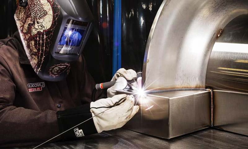
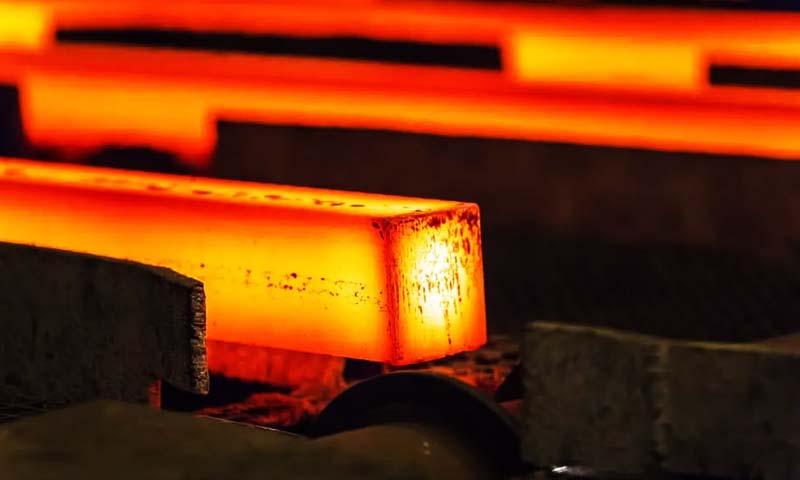
- Thermal Origins: Temperature gradients during heating/cooling (e.g., casting solidification, welding thermal cycles) lead to uneven expansion/contraction, generating thermal residual stress—accounting for 60% of industrial residual stress cases.
- Mechanical Origins: Uneven plastic deformation during mechanical processing (e.g., machining, stamping, cold rolling) creates dislocations and lattice distortions, forming mechanical residual stress.
- Phase Transformation Origins: Volume changes during solid-state phase transformations (e.g., austenite→martensite in quenching) induce transformational residual stress, common in heat-treated high-strength steels.
2. Why Relieve Residual Stress?
Enhance Fatigue Life
- Tensile residual stress adds directly to cyclic stresses, increasing crack-initiation probability.
Removing or counteracting surface tensile stress (for example with compressive peening) reliably improves fatigue life; reported improvements vary widely with geometry and loading but doubling or more of life is plausible for many welded joints and peened surfaces.
Avoid single-number claims without reference geometry and load case.
Improve Dimensional Stability
- Relieving residual stress reduces machining and assembly distortion. Quantified benefits depend on geometry and the proportion of stress released during machining.
Expect substantial reductions in post-machining drift for heavily stressed forgings and castings when proper pre-machining relief is applied.
Strengthen Corrosion Resistance
- Tensile residual stress accelerates stress corrosion cracking (SCC) and pitting corrosion by creating electrochemical corrosion cells at stress-concentrated sites.
Stress relief converts tensile stress to low-level compressive stress or eliminates it, improving corrosion performance.
Optimize Machinability and Processing Yield
- Stress relief reduces rework/scrap from warpage; it also stabilizes machining tolerances and tool performance in many cases.
Quantify expected yield improvements with pilot trials and measurement.
3. Residual-stress measurement

Key measurement methods and practical limits
- X-ray diffraction (XRD) — surface method with effective sampling depth typically in the micrometre range (often ~5–20 µm, depending on X-ray energy and coating);
suitable for surface stress, resolution depends on instrument and technique (typical uncertainty ≈ ±10–30 MPa under good lab control). - Hole-drilling (ASTM E837) — semi-destructive technique for near-surface profiles;
standard implementations commonly measure to ~1 mm depth in metals using incremental drilling and appropriate data reduction; deeper measurement requires adapted methods and careful calibration. - Neutron diffraction — non-destructive bulk measurement able to probe centimeters into metals; powerful for internal stress mapping of large components but requires access to neutron facilities and considerable cost/time.
- Contour method — destructive, but provides 2-D map of residual stress on a cut plane; effective for complex internal stress states.
- Other methods — ultrasonic, Barkhausen noise, and magnetic techniques are useful for screening but less direct than diffraction or hole-drilling.
4. Residual-stress relief methods
Residual-stress relief methods fall into three broad categories — thermal, mechanical / surface, and hybrid — plus a set of specialised techniques used for niche or high-value components.
Thermal Residual Stress Relief Technologies
Mechanism. Heating raises dislocation mobility and activates creep and recovery processes so locked-in stresses relax through plastic flow, recovery and (if high enough) recrystallisation.
Thermal methods can act through the full section and are the default for bulk macroscopic stress.
Principal techniques
- Stress-relief anneal (TSR): heat to a stress-relief temperature below transformation or solution temperatures, hold (soak), then cool at a controlled rate.
-
- Typical guidance (material dependent):
-
-
- Carbon steels: ~450–700 °C (commonly 540–650 °C for many weldments); hold time scaled to thickness (rule-of-thumb: 1–2 h per 25 mm is often quoted but should be validated).
- Alloy steels / tool steels: tempering or lower PWHT temperatures per metallurgy; avoid over-tempering.
- Aluminium alloys: low-temperature stress relief / aging ~100–200 °C; follow alloy temper instructions.
- Austenitic stainless steels: conventional low-temp “stress relief” has limited effectiveness; solution anneal (~1 000–1 100 °C) is used for microstructural reset but will change dimensions and surface oxide.
-
-
- Effectiveness: typically reduces macroscopic stresses by ~50–90% depending on geometry and restraint.
- Risks: distortion from thermal gradients, decarburization/oxidation, microstructural softening or precipitation (carbides, sigma-phase) if temperatures or holds are inappropriate.
- Post-weld heat treatment (PWHT): a targeted SR cycle applied to welded assemblies to temper martensite and reduce HAZ stresses.
Parameters must comply with relevant codes (ASME, EN, etc.) and metallurgical constraints. - Solution anneal and quench (for certain alloys): dissolves precipitates and re-establishes homogeneous microstructure; rapid cooling required to avoid re-precipitation.
Used for some stainless, duplex and cast super-duplex alloys. - Hot Isostatic Pressing (HIP): combined high temperature and high isostatic pressure.
HIP collapses internal porosity and drives plastic flow under pressure, reducing internal stress and defects.
Very effective for castings and additive parts where internal defects and residual stresses co-exist, but expensive and limited to parts/economics that justify it.
When to use: thick sections, heavily constrained welded assemblies, heavy castings, parts where through-thickness stress relief is required and thermal metallurgy allows safe annealing.
Mechanical and deformation-based methods (bulk and local)
Mechanism. Induced controlled plastic deformation redistributes residual stress; applied loads can be elastic-plastic or purely plastic and can be global (stretching) or local (straightening).
Principal techniques
- Stretching / prestretch: apply controlled axial plastic strain to bars, rods or ductile parts.
Effective for long, prismatic shapes and wire/rod production to reduce locked-in longitudinal stress.
-
- Effectiveness: very good for the axial component; not for complex geometries.
- Mechanical straightening / plastic bending: deliberate plastification to counteract known distortions or to relax built-in curvature.
- Controlled compressive loading: used in some plates/panels to redistribute tensile residuals; must be carefully engineered to avoid new damage.
When to use: parts that tolerate controlled plastic change and when thermal methods are impractical or would damage temper/finish. Mechanical methods are fast and low-cost but can introduce shape changes.
Surface engineering methods (induce beneficial compressive layers)
Mechanism. Create a near-surface plastically deformed layer with high compressive residual stress — this does not remove deep tensile core stresses but offsets their effect for surface-initiated failures (fatigue, SCC).
Principal techniques
- Shot peening / blast peening: impact media create controlled surface plastic strain and compressive stress.
-
- Typical parameters: Almen intensity, shot size/pattern and coverage.
- Depth: compressive layer typically 0.1–1.5 mm, depending on shot energy and material.
- Typical near-surface compressive stresses: up to several hundred MPa near the surface.
- Applications: gears, springs, shafts, weld toes; well-established and cost-effective.
- Laser peening: laser-induced shock produces deeper compressive layers (commonly 1–3 mm, in some reports deeper), with excellent control and minimal surface roughness increase. Highly effective but capital-intensive.
- Ultrasonic impact treatment (UIT) / ultrasonic peening: targeted weld-toe improvement, good for fatigue life of welded joints.
- Roller / hammer burnishing, low-plasticity surface rolling: produce smoother finishes and compressive residuals with minimal surface topology change.
When to use: fatigue-critical surfaces, welded joints subject to cyclic loading, components where surface cracks dominate failure.
Surface methods are standard for life extension where through-thickness relief is not required.
Vibration stress relief (VSR)
Mechanism. Vibrate the component at resonant or near-resonant frequencies to produce small, repeated plastic micro-movements that relax residual stress.
Practice notes
- Typical excitation: natural frequencies in the tens to a few hundreds of Hz range; process durations commonly 0.5–2 hours depending on part.
- Effectiveness: results vary widely with geometry, initial stress state and setup.
In favourable cases VSR achieves tens of percent reduction; however outcomes are inconsistent and must be validated by measurement. - Advantages: portable, no high temperature, can be applied in situ to welded structures that cannot enter a furnace.
- Limitations: not reliable for deep tensile cores, complex parts or when large reductions are required without validation.
Engineering recommendation: use VSR only after pilot trials and objective pre/post measurement (hole-drilling, strain gauges).
Treat it as a pragmatic but empirically validated option rather than a guaranteed cure.
Cryogenic and low-temperature treatments
Mechanism. Cryogenic cycles can transform retained austenite, change dislocation structures and marginally alter residual stress fields.
Predominantly used in tool steels and cutting tools to enhance wear resistance and dimensional stability.
When to use: specialised applications (tooling, cutting edges) where microstructural phase changes (retained austenite → martensite) are desirable; not a general bulk stress-relief method for structural parts.
Hybrid and advanced methods
Mechanism. Combine thermal and mechanical actions to extend effectiveness (e.g., heat to lower yield and apply mechanical load, or use vibration during mild heating).
Examples
- Thermo-mechanical relief: heat to a sub-critical temperature to lower yield strength, then apply controlled load or vibration.
Can achieve deeper relief at lower peak temperatures and with less distortion than full anneal. - Ultrasonic-assisted thermal cycles / laser-assisted treatments: accelerate diffusion or increase plasticity locally, enabling lower thermal budgets. These are emerging and often application-specific.
When to use: complex, high-value, or heat-sensitive components where pure thermal treatment is undesirable and where capital investment is justified.
Hot Isostatic Pressing (HIP) — specialty bulk treatment
Mechanism. Elevated temperature under isostatic gas pressure causes plastic flow and closure of internal voids and reduces internal residual stress while improving density.
Use cases: castings and additively manufactured parts with internal porosity or unacceptable internal stress concentrations.
HIP is uniquely capable of simultaneously healing defects and relaxing stresses but is expensive and limited by part size and economics.
5. Practical selection matrix
- Bulk thick castings / heavily restrained weldments:Thermal stress relief (TSR / PWHT) or HIP when porosity coexists.
- Fatigue-critical surfaces / weld toes:Shot peening, UIT or laser peening.
- Large welded structures where furnace is impossible:Validated VSR + targeted mechanical pre-distortion and localized peening; require measurement validation.
- Additively manufactured parts: consider in-process heating, post-build stress relief, and HIP for critical components.
- Small precision parts (tight dimensional tolerances): low-temperature thermal relief or mechanical methods designed to minimize distortion (e.g., constrained low-temp anneal, controlled stretching).
6. Practical cautions and metallurgical interactions
- Avoid inappropriate tempering: stress relief temperatures can change hardness, tensile strength and microstructure — always consult materials data (e.g., tempering curves for quenched steels).
- Watch for phase precipitation: long holds in some ranges promote carbide, sigma phase, or other deleterious precipitates in stainless and duplex alloys.
- Dimension control: thermal cycles and HIP may cause growth/relief of residual stresses but also dimensional changes — plan fixtures and post-process machining accordingly.
- Safety & environment: decarburization, scale, and loss of corrosion resistance are real risks with open-air furnaces — consider controlled atmospheres or protective coatings.
7. Conclusions
- Residual stresses are common and can materially affect performance.
They vary widely by process and geometry; realistic magnitudes are typically tens to a few hundred MPa, with extremes approaching yield in highly constrained cases. - Method selection must be evidence-based: identify the stress location and depth, define acceptance criteria, pilot with representative specimens, and verify numerically and by measurement.
- Thermal relief remains the most generally effective for bulk stresses; surface peening and laser methods are powerful for fatigue-critical surfaces;
VSR can be useful but requires validation for each application. HIP is uniquely powerful where internal defects and internal stress coincide.
FAQs
What is the most thorough residual stress relief method?
Stress relief annealing is the most thorough, eliminating 70–90% of residual stress, ideal for bulk components like castings and welds.
Which method is suitable for precision components to avoid deformation?
Vibratory Stress Relief (VSR) or isothermal aging is preferred, as they cause minimal deformation (<0.005 mm) while relieving 50–80% stress.
Can residual stress be completely eliminated?
No—engineering practice targets eliminating 50–95% of harmful residual stress; complete elimination is unnecessary and may introduce new stress via over-processing.
Is residual stress relief mandatory for welding components?
Yes, for critical welding components (pipelines, pressure vessels, aerospace parts), stress relief is mandatory to prevent fatigue failure and stress corrosion cracking.
How to verify the effect of residual stress relief?
Use standardized methods: X-ray diffraction (surface stress) or hole-drilling (subsurface stress) to measure residual stress before and after relief, with a reduction rate ≥50% indicating qualified relief.