

W branży produkcyjnej, zrozumienie pełnego spektrum metod obróbki jest niezbędne dla inżynierów procesu, mechanicy, i planistów produkcji.
Przez lata, nowicjusze w tej dziedzinie mieli trudności z rozróżnieniem różnych procesów skrawania – kiedy wykonać skręt, kiedy frezować, kiedy szlifować, a kiedy całkowicie zrezygnować z metod tradycyjnych na rzecz procesów elektrycznych lub laserowych.
To zamieszanie jest zrozumiałe. W ciągu ostatniego stulecia obszar obróbki skrawaniem znacznie się rozwinął, ewoluuje od prostej ręcznej pracy tokarskiej do wyrafinowanego ekosystemu CNC Mękawka centra, maszyny wyładowcze elektryczne, wycinarki laserowe, i systemy waterjet.
Każdy proces ma swoje mocne strony, ograniczenia, i idealne zastosowania — a wybranie niewłaściwego może prowadzić do złomowania części, uszkodzone narzędzia, i niepotrzebne koszty.
W tym artykule systematycznie wyjaśniamy 13 wspólne metody obróbki, w tym 8 tradycyjne procesy obróbki i 5 specjalne technologie obróbki, pomagając inżynierom zrozumieć ich zasady, zalety, ograniczenia, i typowe zastosowania.
1. Trzy podstawowe zasady formowania części
Każdy element mechaniczny, od prostej podkładki po skomplikowaną łopatkę turbiny, jest wytwarzany zgodnie z jedną z trzech podstawowych zasad produkcji.
Zasady te definiują sposób przekształcania materiału z surowca w gotową część i służą jako podstawowe rozróżnienie pomiędzy różnymi metodami przetwarzania.
Zasada 1: Formacja materialna (Δm ≈ 0)
W procesach formowania materiału, całkowita masa przedmiotu obrabianego pozostaje prawie niezmieniona przed i po obróbce.
Zamiast usuwać lub dodawać materiał, istniejący materiał zostaje przekształcony odkształcenie plastyczne, transformacja fazowa, lub zestalenie.
Procesy te wykorzystywane są głównie do wytwarzania wstępnych kształtów komponentów, powszechnie nazywany puste miejsca, preformy, lub części o kształcie zbliżonym do siatki.
Uformowane części można następnie poddać wtórnym operacjom obróbki w celu uzyskania dokładnych wymiarów i wymagań dotyczących powierzchni.
Procesy formowania materiału są szczególnie ważne, ponieważ determinują podstawową strukturę materiału, właściwości mechaniczne, i wydajność produkcji końcowego komponentu.
| Proces | Mechanizm produkcyjny | Typowe zastosowania | Kluczowe zalety |
| Odlew | Roztopiony metal wlewa się do wnęki formy i zestala, nadając mu pożądany kształt. | Pompowanie obudowa, ciała zaworów, bloki silnika, bazy maszynowe, złożone elementy konstrukcyjne. | Tworzy bardzo złożone geometrie, fragmenty wewnętrzne, i duże komponenty przy stosunkowo niskim zużyciu materiału. |
| Kucie | Podgrzany metal jest kształtowany za pomocą sił ściskających za pomocą matryc, prasy, lub młotki. | Wały, Przekładnie, Podłączanie prętów, składniki ciśnieniowe, Struktury lotnicze. | Poprawia właściwości mechaniczne poprzez udoskonalony przepływ ziaren, wyższa siła, i doskonałą odporność na zmęczenie. |
Metallurgia proszkowa |
Proszki metali są prasowane pod ciśnieniem i spiekane w podwyższonych temperaturach, tworząc stałe składniki. | Namiar, filtry, Przekładnie, elementy odporne na zużycie, części precyzyjne. | Niezwykle wysokie wykorzystanie materiału, kontrolowana porowatość, i możliwość wytwarzania specjalnych kompozycji materiałowych. |
Kluczowy wgląd: Chociaż procesy te nie są „obróbką skrawaniem” w tradycyjnym znaczeniu, stanowią materiał wyjściowy — półfabrykat — wymagany przez większość precyzyjnych komponentów.
Zasada 2: Usuwanie materiału (Δm < 0)
Usuwanie materiału, znany również jako Produkcja odejmująca, jest podstawową zasadą konwencjonalnej obróbki.
W tych procesach, nadmiar materiału jest usuwany z początkowego przedmiotu obrabianego, takiego jak odlew, kucie, zapasy barowe, lub płyta — aby stworzyć ostateczną geometrię o dokładnych wymiarach, tolerancje, i wykończenia powierzchni.
W tej kategorii znajdują się najczęściej stosowane metody obróbki:
- Obrócenie.
- Przemiał.
- Wiercenie.
- Nudny.
- Szlifowanie.
- Obróbka przekładni.
- Obróbka elektryczna (EDM).
Usuwanie materiału pozostaje dominującym podejściem do produkcji precyzyjnych komponentów mechanicznych, ponieważ zapewnia doskonałą kontrolę nad końcową jakością części.
Charakterystyka podstawowa:
- Materiał jest usuwany, wytwarzanie wiórów lub opiłków.
- Osiąga najwyższą dokładność wymiarową i wykończenie powierzchni.
- Najpowszechniej stosowana metoda wytwarzania precyzyjnych elementów.
Kluczowy wgląd
Usuwanie materiału jest podstawą precyzyjnej produkcji, ponieważ przekształca półfabrykaty o kształcie zbliżonym do netto w funkcjonalne komponenty inżynieryjne.
Typowa ścieżka produkcji przemysłowej często przebiega według tego schematu:
Odlew / Kucie → Obróbka zgrubna → Obróbka cieplna → Obróbka precyzyjna → Wykańczanie powierzchni
Ta kombinacja równoważy efektywność materiałową, Wydajność mechaniczna, i dokładność wymiarowa.
Zasada 3: Dodatek materiału (Δm > 0)
Procesy dodawania materiałów tworzą komponenty poprzez dodawanie, deponowanie, lub łączenie materiałów ze sobą.
W przeciwieństwie do produkcji subtraktywnej, który usuwa nadmiar materiału, procesy addytywne zwiększają ilość materiału podczas produkcji.
W tej kategorii znajdują się zarówno tradycyjne technologie łączenia, jak i nowoczesne metody wytwarzania przyrostowego.
| Proces | Mechanizm produkcyjny | Typowe zastosowania | Kluczowe zalety |
| Spawalniczy | Materiały łączone są na gorąco, ciśnienie, lub połączenie obu w celu stworzenia trwałej więzi. | Ramy strukturalne, rurociągi, naczynia ciśnieniowe, czołgi, Ciężki sprzęt. | Tworzy mocne, trwałe połączenia i umożliwia wydajną produkcję dużych konstrukcji. |
| Mosiężnictwo / Lutowanie | Metal wypełniający topi się i rozprowadza pomiędzy komponentami bez topienia materiałów podstawowych. | Wymienniki ciepła, komponenty elektroniczne, zespoły precyzyjne. | Umożliwia łączenie różnych materiałów przy minimalnych odkształceniach termicznych. |
3D drukowanie (Produkcja addytywna) |
Materiał jest osadzany warstwa po warstwie zgodnie z modelem cyfrowym. | Prototypy, Lekkie struktury, niestandardowe części medyczne, złożone geometrie. | Zapewnia wyjątkową swobodę projektowania i umożliwia szybką produkcję skomplikowanych kształtów. |
Kluczowy wgląd: Produkcja przyrostowa jest szczególnie cenna w przypadku prototypowania, części niestandardowe, i geometrie, które są niemożliwe lub niezwykle trudne do osiągnięcia metodami subtraktywnymi.
2. . 8 Tradycyjne procesy obróbki: Podstawa produkcji
Tradycyjna obróbka opiera się na mechanicznych narzędziach skrawających, które usuwają materiał z przedmiotu obrabianego.
Procesy te są końmi pociągowymi przemysłu produkcyjnego, jesteśmy w stanie wyprodukować wszystko, od prostych wałów po złożone formy i matryce. Oto 8 najczęstsze tradycyjne procesy, ich zasady pracy, i ich idealne zastosowania.
Obrócenie: Proces części obrotowych
Zasada pracy:
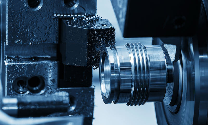
CNC Turning to proces obróbki, podczas którego przedmiot obrabiany obraca się (ruch pierwotny) a jednopunktowe narzędzie tnące porusza się liniowo (ruch posuwu).
Tokarka jest obrabiarką służącą do operacji toczenia. Gdy obrabiany przedmiot się obraca, narzędzie usuwa materiał w celu utworzenia profili cylindrycznych, twarze, zwężające się, wątki, i inne funkcje obrotowe.

Dlaczego wyróżniać się:
Toczenie zapewnia wyjątkową precyzję części obrotowych ze względu na naturalną stabilność procesu.
Obracający się przedmiot obrabiany zapewnia, że wszystkie elementy są koncentryczne w stosunku do tej samej osi, co ułatwia osiągnięcie doskonałej współosiowości i prostopadłości pomiędzy powierzchniami.
Proces cięcia jest ciągły (żadnych przerw), pozwalających na osiągnięcie dużych prędkości skrawania, Doskonałe wykończenie powierzchniowe, i długą żywotność narzędzia.
| Parametr | Typowy zakres | Notatki |
| Chropowatość powierzchni | Ra 0.1 - - 3.2 µm | Toczenie diamentowe metali nieżelaznych może osiągnąć Ra <0.1 µm. |
| Dokładność wymiarowa | ±0,01 – 0.05 mm | Tokarki precyzyjne mogą osiągnąć ±0,005 mm. |
| Typowe materiały | Metale, tworzywa sztuczne, kompozyty | Nie nadaje się do bardzo twardych materiałów (>HRC 60) bez specjalnego oprzyrządowania. |
Aplikacje:
- Części cylindryczne: Wały, szpilki, Rolki
- Części w kształcie dysku: kołnierze, Przekładnie, Koła zamachowe
- Elementy gwintowane: śruby, śruby, orzechy
- Części mimośrodowe i nieokrągłe (na tokarkach krzywkowych)
Typy maszyn:
- Tokarki poziome: Najczęstszy typ; obsługuje szeroką gamę rozmiarów części.
- Tokarki pionowe: Używany do dużych, ciężkie elementy w kształcie dysku (NP., Bębny hamulcowe, duże przekładnie).
- Typ szwajcarski (automatyczny) Tokarki: Idealny do małych, długi, i złożone części (NP., komponenty zegarka, urządzenia medyczne).
- Centra tokarskie CNC: Maszyny wieloosiowe zdolne do wykonywania skomplikowanych operacji (obrócenie, przemiał, wiercenie) w jednym ustawieniu.
Praktyczna wskazówka: Toczenie jest procesem z wyboru dla każdej części z dominującą osią obrotu. Do produkcji o dużej objętości, Tokarki CNC z podajnikami prętów mogą pracować bez nadzoru przez wiele godzin.
Przemiał: Wszechstronny i wszechstronny
Zasada pracy:
Frezowanie CNC wykorzystuje obrotowy frez wielozębny (ruch pierwotny) do usuwania materiału z nieruchomego lub poruszającego się przedmiotu obrabianego.
Oś frezu jest zazwyczaj prostopadła do powierzchni przedmiotu obrabianego (frezowanie końcowe) lub równolegle do niego (frezowanie obwodowe).
Frezowanie może wytworzyć płaskie powierzchnie, szczeliny, kieszenie, kontury, i złożone kształty 3D.

Dlaczego frezowanie jest doskonałe:
Frezowanie jest najbardziej wszechstronnym procesem obróbki. Z odpowiednim frezem i ustawieniem, może obrabiać prawie każdą cechę przedmiotu obrabianego: płaskie powierzchnie, rowki, profile, wnęki, a nawet złożone powierzchnie 3D.
Przerywane działanie tnące, jednocześnie generując pewne wibracje, pozwala na wysoką wydajność usuwania metalu.
Kluczowe rozróżnienie: Frezowanie w górę vs. Frezowanie w dół:
| Typ frezowania | Odcinanie akcji | Najlepsze dla | Życie narzędzi |
| Frezowanie w górę (Standardowy) | Grubość wióra wzrasta od zera do maksimum. | Starsze maszyny z luzem; odlewy i odkuwki z twardym naskórkiem. | Krótszy (z powodu otarcia przy wejściu). |
| Frezowanie w dół (Wspinać się) | Grubość wióra zmniejsza się od maksimum do zera. | Maszyny CNC z kompensacją luzów; Lepsze wykończenie powierzchni. | Dłużej (czystszy wpis; mniej tarcia). |
Metody cięcia:
- Frezowanie końcowe: Oś frezu prostopadła do przedmiotu obrabianego; używany do gniazd, kieszenie, i profile.
- Frezowanie obwodowe: Oś frezu równoległa do przedmiotu obrabianego; stosowany do powierzchni płaskich.
- Frezowanie czołowe: Frez płaski z płytkami; stosowany do dużych płaskich powierzchni.
- Cięcie much: Narzędzie jednopunktowe do dużych płaskich powierzchni; niska wydajność produkcji, ale dobre wykończenie.
Aplikacje:
- Płaskie powierzchnie: najlepsze twarze, Podkładki montażowe
- Szczeliny i rowki: Rowki T, Klucze, jaskółcze ogony
- Złożone profile: Przekładnie, Cams, przeszkody
- 3Kontury D: wnęki pleśniowe, powierzchnie matrycy, Komponenty lotnicze
- Frezowanie gwintów: wysokiej jakości nici w twardych materiałach
Tolerancje i wykończenie powierzchni:
| Parametr | Typowy zakres |
| Chropowatość powierzchni | Ra 0.8 - - 6.3 µm |
| Dokładność wymiarowa | ±0,02 – 0.10 mm |
| Precyzyjne frezowanie | ±0,005 – 0.01 mm (z wysokiej klasy sprzętem) |
Praktyczna wskazówka: Podczas frezowania, zawsze bierz pod uwagę sztywność konfiguracji. Długi, smukłe ostrza ulegną odkształceniu, co prowadzi do złego wykończenia powierzchni i niedokładności. Użyj krótkiego, tam, gdzie to możliwe, sztywne oprzyrządowanie.
Struganie: Niedrogie rozwiązanie do płaskich powierzchni
Zasada pracy:
Struganie to proces obróbki, w którym jednopunktowe narzędzie skrawające porusza się po linii prostej (ruch pierwotny), cięcie w poprzek przedmiotu obrabianego trzymanego na stole posuwisto-zwrotnym.
Przedmiot obrabiany przesuwa się obok nieruchomego narzędzia, który usuwa warstwę materiału przy każdym przejściu. Narzędzie powraca do punktu początkowego bez cięcia (skok jałowy).
Dlaczego planowanie jest doskonałe:
Struganie to niedrogie rozwiązanie do obróbki dużych powierzchni, płaskie powierzchnie, szczególnie w przypadku pojedynczych części lub małych partii.
Maszyny są stosunkowo proste i niedrogie, a oprzyrządowanie jest podstawowe (Narzędzia HSS).
Długi, proste pociągnięcia są idealne do obróbki prostych powierzchni, takich jak łoża maszyn, prowadnice, i duże płyty podstawy.
| Parametr | Typowy zakres | Notatki |
| Chropowatość powierzchni | Ra 1.6 - - 6.3 µm | Dobre, ale bardziej szorstkie niż frezowanie. |
| Dokładność wymiarowa | ±0,05 – 0.20 mm | Mniej precyzyjne niż frezowanie. |
| Wskaźnik produkcji | Niski | Jałowy ruch powoduje stratę czasu. |
Aplikacje:
- Duży, płaskie powierzchnie: bazy maszynowe, łóżka, i stoły
- Proste rowki: Rowki V, jaskółcze ogony, Klucze
- Pojedyncze części i zlecenia w małych partiach: prace naprawcze i konserwacyjne
- Zastosowania w narzędziowniach i matrycach
Ograniczenia:
- Niska produktywność: skok jałowy ogranicza wydajność produkcji.
- Niska precyzja: nie tak dokładne jak frezowanie.
- Ograniczone kształty: może tworzyć tylko elementy płaskie lub proste.
Praktyczna wskazówka: Struganie najlepiej nadaje się do prac, w których koszt frezarki lub konfiguracji jest wygórowany. Jest rzadko stosowany w produkcji wielkoseryjnej.
Wiercenie: Podstawa wykonywania otworów
Zasada pracy:
Wiercenie to proces tworzenia okrągłego otworu w przedmiocie obrabianym za pomocą obrotowego wielopunktowego narzędzia tnącego zwanego wiertłem (lub wiertło kręte).
Wiertło obraca się (ruch pierwotny) i jest podawany do przedmiotu obrabianego (ruch paszowy). Krawędzie tnące na końcu usuwają materiał, podczas gdy flety odprowadzają wióry.
Dlaczego wiercenie jest doskonałe:
Wiercenie to najprostszy i najbardziej ekonomiczny sposób tworzenia otworów w metalu.
Można go wykonać na szerokiej gamie obrabiarek: wiertarki, Mierzyny, a nawet wiertarki ręczne. Wiercenie jest zazwyczaj pierwszym krokiem w sekwencji operacji wiercenia otworów.
| Parametr | Typowy zakres | Notatki |
| Zakres wielkości otworów | 0.1 - - 100+ mm | Małe otwory wymagają specjalnych mikrowierteł. |
| Głębokość otworu | Do 10× średnicy (standard) | Głębokie otwory wymagają specjalistycznego oprzyrządowania (wiercenie pistoletowe). |
| Dokładność wymiarowa | ±0,05 – 0.2 mm | Wiercenie jest operacją zgrubną; otwory mogą być zbyt duże. |
| Wykończenie powierzchni | Ra 3.2 - - 12.5 µm | Stosunkowo słaba w porównaniu do rozwiercania. |
Typowe operacje związane z wierceniem:
| Działanie | Opis | Zamiar |
| Rozwierc | Powiększa i wykańcza istniejący otwór do dokładnej średnicy. | Precyzyjne wymiarowanie otworów; poprawiona okrągłość i wykończenie powierzchni. |
| Pogłębianie | Powiększa górną część otworu do większej średnicy. | Tworzy występ dla łba śruby (śruba z łbem gniazdowym). |
| Pogłębianie | Tworzy stożkowe zwężenie na górze otworu. | Do śrub z łbem płaskim i gratowania. |
| Stukający | Wycina gwinty wewnętrzne w otworze. | Do elementów złącznych gwintowanych. |
Typowe problemy z wierceniem:
| Problem | Przyczyna | Rozwiązanie |
| Za duża dziura | Wiertło kołysze się; zużyte wiertło; niewłaściwe karmienie. | Użyj wiertła centralnego; sprawdź ustawienie wiertła; zmniejszyć paszę. |
| Błąd lokalizacji otworu | Ruch przedmiotu obrabianego; kiepski układ. | Zabezpiecz obrabiany przedmiot; użyj szablonu do wiercenia. |
| Tworzenie się zadziorów | Niewłaściwe parametry wiercenia. | Użyj operacji gratowania; zmniejsz posuw na wyjściu. |
Praktyczna wskazówka: Do precyzyjnego wykonywania otworów, zawsze zaczynaj od wiertła centralnego, aby stworzyć precyzyjny punkt początkowy, następnie wywiercić na wymiar, i wreszcie rozwiercić do ostatecznego wymiaru.
Nudny: Proces precyzyjnego powiększania
Zasada pracy:
Wytaczanie to proces powiększania i udoskonalania istniejącego otworu w celu uzyskania dokładnego rozmiaru, okrągłość, i wykończenie powierzchni.
Wytaczanie wykonuje się na tokarce (przy użyciu wytaczaka) lub na wytaczarce.
Narzędzie jednopunktowe jest wprowadzane do otworu wzdłuż osi, usunięcie cienkiej warstwy materiału.
Dlaczego nudne Excels:
Wytaczanie to proces z wyboru, pozwalający uzyskać wysoką dokładność średnic otworów, koncentryczność, i wyrównanie.
Może skorygować błędy pozycjonowania z poprzednich operacji (NP., wiercenie) i jest niezbędny w przypadku dużych i głębokich otworów, których nie można dokładnie rozwiercić ani wywiercić.
| Parametr | Typowy zakres | Notatki |
| Średnica otworu | 5 - - 500+ mm | Ograniczone średnicą wytaczaka. |
| Głębokość | Ograniczone sztywnością narzędzia. | Głębokie otwory wymagają sztywnego mocowania, dobrze obsługiwany wytaczak. |
| Dokładność wymiarowa | ±0,01 – 0.05 mm | Wytaczanie precyzyjne jest bardzo dokładne. |
| Wykończenie powierzchni | Ra 0.4 - - 3.2 µm | Bardzo dobry. |
Aplikacje:
- Precyzyjne otwory: noszące obudowy, cylindry silnika, Składniki hydrauliczne
- Wyrównywanie otworów: gdzie wiele otworów wymaga precyzyjnej współosiowości
- Otwory o dużej średnicy: otwory są zbyt duże dla standardowych rozwiertaków
- Korekta istniejących dziur: naprawianie uszkodzonych lub źle ustawionych otworów
Praktyczna wskazówka: Wytaczaki muszą być sztywne; nawet niewielkie odchylenie może powodować drgania i niedokładności. Stosować możliwie najkrótszy wysięg narzędzia.
Cięcie kół zębatych i obróbka profili zębów
Zasada pracy:
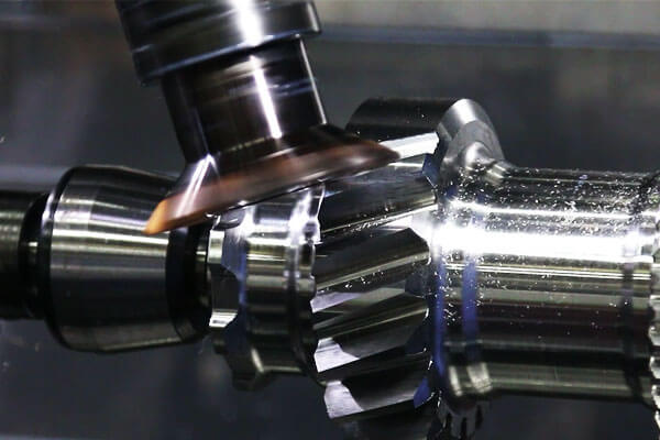
Bieg Cięcie obejmuje szereg procesów stosowanych do produkcji zębów kół zębatych, Splajny, i inne elementy zębate. Dwie najczęstsze metody to hobowanie I kształtowanie przekładni.
- Hobbing: Obrotowy nóż (płyta) jest podawany przez obracający się przedmiot obrabiany, wytwarzanie zębów przekładni poprzez ciągłe działanie tnące. Hobbing jest wysoce produktywny i szeroko stosowany w przekładniach czołowych i śrubowych.
- Kształtowanie przekładni: W obrabiany przedmiot wciskany jest frez posuwisto-zwrotny o tym samym profilu zębów co koło zębate, generowanie zębów pojedynczo. Kształtowanie jest wolniejsze, ale może wytworzyć wewnętrzne koła zębate i niektóre skomplikowane profile.
Dlaczego obróbka kół zębatych jest doskonała:
Procesy cięcia kół zębatych są specjalnie zaprojektowane w celu zapewnienia dokładności, mocny, i cichobieżne zęby przekładni. Są standardową metodą produkcji większości kół zębatych i wielowypustów.
Typowy zakres wydajności obróbki kół zębatych
| Parametr | Typowy zakres | Notatki |
| Moduł / Diametral Pitch | Moduł 0,5–20+ | Obejmuje małe przekładnie precyzyjne i duże przekładnie przemysłowe. |
| Średnica przekładni | 10–1000+ mm | Ograniczone głównie wydajnością maszyny. |
| Dokładność zębów | Klasa ISO 5–8 | Wyższe gatunki są używane do zastosowań precyzyjnych. |
| Chropowatość powierzchni | RA 0,8-3,2 μm | Gładkie powierzchnie zębów zmniejszają tarcie i hałas podczas pracy. |
| Typowe materiały | Stal węglowa, stal ze stopu, stal nierdzewna, lane żelazo, brązowy | Wybór materiału zależy od obciążenia, prędkość, i środowisko. |
Typowe metody cięcia kół zębatych i obróbki profili zębów
| Metoda | Zasada pracy | Najlepsze aplikacje |
| Hobowanie przekładni | Obrotowy frez płytowy w sposób ciągły generuje zęby koła zębatego, podczas gdy przedmiot obrabiany obraca się synchronicznie. | Produkcja wielkoseryjna kół zębatych czołowych, przekładnie śrubowe, i przemysłowe przekładnie zębate. |
| Kształtowanie przekładni | Frez posuwisto-zwrotny wytwarza zęby poprzez zsynchronizowany ruch cięcia. | Przekładnie wewnętrzne, Splajny, przekładnie barkowe, i złożone profile przekładni. |
Broaching |
Przeciągacz wielozębny usuwa materiał w jednym, postępowym przejściu. | Produkcja wielkoseryjna przekładni wewnętrznych, Klucze, i splajny. |
| Frezowanie kształtowe | Uformowany frez wycina poszczególne przestrzenie międzyzębowe zgodnie z wymaganym profilem. | Duże przekładnie, małe partie, prace naprawcze, i niestandardowe projekty narzędzi. |
| Szlifowanie biegów | Proces wykańczania ściernego polega na usunięciu niewielkich ilości materiału po obróbce cieplnej. | Precyzyjnie hartowane koła zębate stosowane w motoryzacji, lotniczy, oraz maszyny o wysokiej wydajności. |
Praktyczna wskazówka: Obróbka obwiedniowa kół zębatych jest najbardziej ekonomiczną metodą produkcji przekładni na dużą skalę. Kształtowanie stosuje się w przypadku kół zębatych wewnętrznych i skomplikowanych kształtów.
Szlifowanie: Precyzyjny proces wykańczania
Zasada pracy:
Szlifowanie wykorzystuje obracającą się tarczę ścierną (złożony z tysięcy twardych, ostre grysy) do usuwania materiału poprzez kombinację cięcia, orka, i pocieranie.
Tarcza ścierna pełni funkcję wielozębnego narzędzia tnącego, ale z ujemnym kątem natarcia, co daje bardzo gładką powierzchnię, powierzchnia o wysokiej precyzji.
Dlaczego szlifowanie jest doskonałe:
Szlifowanie jest procesem z wyboru pozwalającym uzyskać najwyższe wykończenie powierzchni i dokładność wymiarową, szczególnie w przypadku materiałów hartowanych (HRC > 45).
Może korygować zniekształcenia obróbki cieplnej i wytwarzać płaskość, powierzchnie równoległe.
| Parametr | Typowy zakres | Notatki |
| Chropowatość powierzchni | Ra 0.05 - - 0.8 µm | Precyzyjne szlifowanie może osiągnąć Ra <0.05 µm. |
| Dokładność wymiarowa | ±0,001 – 0.005 mm | Szlifowanie jest najdokładniejszym procesem obróbki. |
| Twardość materiału | Aż do 70 HRC | Można szlifować stal hartowaną, węgliki. |
| Typowe materiały | Stale hartowane, stale narzędziowe, węgliki, ceramika | Wszystko trudne, kruche materiały. |
Typowe procesy szlifowania:
| Typ | Opis | Aplikacje |
| Szlifowanie powierzchni | Szlifowanie powierzchni płaskich. | Płyty formy, stoły maszynowe, obróbka. |
| Szlifowanie cylindryczne | Szlifowanie zewnętrznych powierzchni cylindrycznych. | Wały, szpilki, czopy łożyskowe. |
| Szlifowanie wewnętrzne | Szlifowanie wewnętrznych powierzchni cylindrycznych. | Obudowy łożysk, otwory cylindrów. |
| Szlifowanie bezkłowe | Szlifowanie cylindryczne bez kłów. | Produkcja wałów na dużą skalę. |
| Szlifowanie narzędzi i frezów | Szlifowanie narzędzi skrawających. | Ostrzenie wierteł, młyny końcowe, Rozwiertaki. |
| Szlifowanie z zasilaniem pełzającym | Głęboko, szlifowanie z powolnym posuwem. | Złożone profile w twardych materiałach. |
Praktyczna wskazówka: Szlifowanie generuje znaczną ilość ciepła, co może spowodować uszkodzenia termiczne (oparzenie szlifierskie) i stres resztkowy. Stosować odpowiednią ilość chłodziwa i odpowiednie parametry szlifowania.
Szlifowanie form: Specjalizacja profilowa
Zasada pracy:
Szlifowanie kształtowe wykorzystuje ściernicę kształtową lub proces sterowany CNC do skomplikowanego szlifowania, profile nieliniowe.
Koło jest ubierane do określonego konturu, który jest następnie szlifowany w przedmiocie obrabianym.
Jest to rozszerzenie szlifowania o specjalistyczne zastosowania, gdzie wymagany jest określony kształt lub profil.
Dlaczego szlifowanie kształtów jest doskonałe:
Szlifowanie kształtowe może zapewnić bardzo precyzyjną obróbkę, złożone profile z materiałów hartowanych, z doskonałym wykończeniem powierzchni i dokładnością wymiarową.
Jest to preferowany proces formowania matryc, uderzenia, i formy.
Aplikacje:
- Wnęki pleśniowe
- Profile matryc
- Skomplikowane kontury w budowie narzędzi i matryc
- Precyzyjne profile w komponentach lotniczych
Praktyczna wskazówka: Szlifowanie kształtowe jest specjalnością, kosztowny proces, uzasadnione tylko tam, gdzie wymagana jest wyjątkowa dokładność i doskonałe wykończenie powierzchni.
3. . 5 Procesy Specjalne: Nietradycyjna obróbka
Tradycyjne narzędzia skrawające mają problemy – lub całkowicie zawodzą – w przypadku bardzo twardych materiałów (stale narzędziowe, węgliki, ceramika), złożone geometrie (głębokie wnęki, mikrofunkcje), lub gdy należy zminimalizować uszkodzenia termiczne lub mechaniczne.
W procesach specjalnych do usuwania materiału wykorzystywane są inne formy energii niż cięcie mechaniczne, oferując rozwiązania tych wyzwań.
Obróbka elektroerozyjna (EDM)
Zasada pracy:
EDM—znana również jako erozja iskrowa — usuwa materiał poprzez serię szybko powtarzających się wyładowań elektrycznych (iskry) pomiędzy elektrodą (narzędzie) i przedmiot obrabiany.
Iskry powodują erozję niewielkich ilości materiału zarówno na elektrodzie, jak i na obrabianym przedmiocie.
Przedmiot obrabiany zanurza się w płynie dielektrycznym (NP., woda dejonizowana lub olej) do kontrolowania wypływu i spłukiwania zerodowanych cząstek.

Rodzaje EDM:
| Typ | Opis | Aplikacje |
| Sinker EDM (Ram EDM) | Elektroda jest ukształtowana zgodnie z negatywem pożądanej wnęki. | Wnęki pleśniowe, umrzeć tonąc, złożone ubytki 3D. |
| Drut EDM (ŚWIĘT) | Cienki, poruszający się stale drut pełni rolę elektrody. | Profile, kontury, części precyzyjne; półfabrykaty do wykrojników. |
| EDM do małych otworów | Elektroda o małej średnicy do dokładnego wiercenia, głębokie dziury. | Otwory chłodzące, dysze wtrysku paliwa. |
Dlaczego EDM jest doskonały:
EDM może obrabiać dowolny materiał przewodzący, niezależnie od jego twardości. Może powodować kompleksy, skomplikowane kształty (łącznie z ostrymi narożnikami) z dużą dokładnością i doskonałym wykończeniem powierzchni.
W procesie nie stosuje się siły mechanicznej, dzięki czemu cienkościenne i delikatne części można obrabiać bez zniekształceń.
| Parametr | Typowy zakres | Notatki |
| Chropowatość powierzchni | Ra 0.2 - - 3.2 µm | Zależy od wykończenia; doskonałe do wykończenia. |
| Dokładność wymiarowa | ±0,005 – 0.02 mm | Wysoka precyzja, zwłaszcza w obróbce elektroerozyjnej. |
| Twardość materiału | Aż do 70 HRC | Praktycznie nieograniczone w przypadku materiałów przewodzących. |
| Przewodność materiału | Musi przewodzić prąd. | Nie nadaje się do ceramiki, tworzywa sztuczne, lub szkło. |
Aplikacje:
- Wnęki i matryce do form
- Formy wtryskowe do tworzyw sztucznych
- Elementy silników lotniczych
- Urządzenia medyczne
- Złożone kontury i profile
Praktyczna wskazówka: EDM to powolny proces, dlatego jest zwykle używany do operacji wykańczających, nie do szorowania.
Obróbka elektrochemiczna (ECM)
Zasada pracy:
ECM to nietradycyjny proces obróbki, który usuwa materiał poprzez rozpuszczanie anodowe. Przedmiot obrabiany (anoda) i ukształtowane narzędzie (katoda) są zanurzone w elektrolicie.
Pomiędzy nimi przepływa wysoki prąd stały, a jony metali są rozpuszczane z przedmiotu obrabianego, które są następnie odprowadzane przez strumień elektrolitu.
Dlaczego ECM wyróżnia się:
ECM może obrabiać twarde i trudne w obróbce materiały bez zużycia narzędzia i strefy wpływu ciepła.
Proces ten zapewnia dużą szybkość usuwania materiału i umożliwia wytwarzanie skomplikowanych kształtów z dobrym wykończeniem powierzchni. Szczególnie nadaje się do usuwania materiałów sypkich.
| Parametr | Typowy zakres | Notatki |
| Chropowatość powierzchni | Ra 0.2 - - 0.8 µm | Bardzo dobre wykończenie. |
| Dokładność wymiarowa | ±0,05 – 0.2 mm | Niższa dokładność niż EDM. |
| Twardość materiału | Aż do 70 HRC | Praktycznie nieograniczone; materiał musi być przewodzący. |
| Szybkość usuwania materiału | Wysoki | Nadaje się do usuwania luzem. |
Aplikacje:
- Łopatki i łopatki silników odrzutowych
- Lufy broni (gwintowanie)
- Implanty medyczne
- Formy do tworzyw sztucznych
- Twardy, złożone komponenty lotnicze
Praktyczna wskazówka: ECM to wyspecjalizowany proces wymagający znacznych inwestycji w sprzęt i obsługę elektrolitu. Jest to uzasadnione dużą wielkością produkcji lub trudnością stosowania metod alternatywnych.
Obróbka laserowa
Zasada pracy:
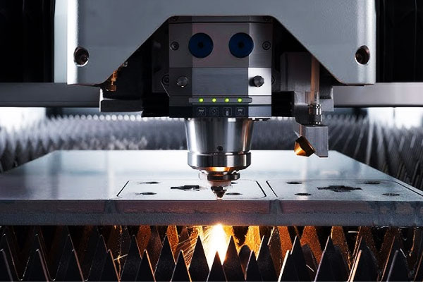
Obróbka laserowa wykorzystuje wysoce skupioną wiązkę spójnego światła (laser) stopić się, odparować, lub usuń materiał z przedmiotu obrabianego.
Plamka lasera przesuwana jest po powierzchni za pomocą sterowanych komputerowo luster lub etapów ruchu.
Dlaczego obróbka laserowa jest doskonała:
Obróbka laserowa jest szybka, dokładny, i bezdotykowy proces. Można go wykonać na dowolnym materiale (metale, tworzywa sztuczne, ceramika, szkło, kompozyty) i może osiągnąć niezwykle doskonałe cechy (do kilku mikronów).
Proces nie generuje sił mechanicznych, dzięki czemu można obrabiać cienkie i delikatne części.
| Parametr | Typowy zakres | Notatki |
| Szerokość szczeliny | 0.02 - - 0.2 mm | Bardzo wąskie cięcia. |
| Prędkość cięcia | Aż do 50 m/my | Wysoka jak na materiały arkuszowe. |
| Rozmiar funkcji | Aż do 10 µm | Do mikroobróbki. |
| Tworzywo | Praktycznie każdy materiał | Metale, tworzywa sztuczne, ceramika, szkło. |
| Dokładność | ±0,01 – 0.05 mm | Wysoka precyzja. |
Aplikacje:
- Cięcie: blacha, profile, rurki
- Wiercenie: precyzyjne otwory, otwory chłodzące
- Grawerowanie i znakowanie: numery części, Logos
- Mikroobróbka: stenty medyczne, Mikroelektronika
- Teksturowanie powierzchni: tworząc mikrochropowatość
Praktyczna wskazówka: Obróbka laserowa generuje strefę wpływu ciepła (Haz). Do materiałów wrażliwych na uszkodzenia termiczne, rozważ użycie krótkiego impulsu (pikosekunda/femtosekunda) lasery.
Obróbka ultradźwiękowa (USM)
Zasada pracy:
W obróbce ultradźwiękowej wykorzystuje się narzędzie wibrujące z dużą częstotliwością (20-40 khz) i amplituda (10-50 µm).
Zawiesina ścierna (NP., węglik boru lub węglik krzemu w wodzie) wprowadza się pomiędzy narzędzie a przedmiot obrabiany.
Narzędzie wibracyjne uderza cząstkami ściernymi w obrabiany przedmiot, usuwanie materiału poprzez mikroodpryski i erozję.
Dlaczego USM wyróżnia się:
USM to proces z wyboru do obróbki twardych i kruchych materiałów, które są trudne lub niemożliwe do obróbki tradycyjnymi metodami.
Jest szczególnie skuteczny w przypadku materiałów nieprzewodzących (ceramika, szkło, kamienie) i materiały o niskiej przewodności elektrycznej.
| Parametr | Typowy zakres | Notatki |
| Chropowatość powierzchni | Ra 0.2 - - 1.6 µm | Dobre wykończenie. |
| Dokładność wymiarowa | ±0,005 – 0.02 mm | Wysoka precyzja. |
| Tworzywo | Twardy, kruchy, materiały nieprzewodzące | Ceramika, szkło, kamienie, węgliki. |
| Zużycie narzędzia | Umiarkowany | Narzędzia zużywają się pod wpływem cząstek ściernych. |
Aplikacje:
- Wiercenie otworów w ceramice i szkle
- Obróbka zaawansowanych kompozytów
- Tonięcie w twardych materiałach
- Elementy półprzewodnikowe i elektroniczne
Praktyczna wskazówka: USM to powolny proces, dlatego zazwyczaj ogranicza się do części o dużej wartości lub trudnych w obróbce.
Obróbka strumieniem wody
Zasada pracy:
W obróbce strumieniem wody wykorzystuje się strumień wody pod wysokim ciśnieniem (z cząsteczkami ściernymi lub bez) do erozji i cięcia materiału. Ciśnienia mogą wahać się od 2,000 Do 6,000 bar (30,000 Do 90,000 psi).
Woda jest przetłaczana przez otwór o małej średnicy, tworząc naddźwiękowy strumień, który uderza w obrabiany przedmiot.
Dlaczego Waterjet jest doskonały:
Obróbka strumieniem wody to proces cięcia na zimno – nie ma strefy wpływu ciepła, brak zniekształceń termicznych, i żadnych zmian metalurgicznych.
Może ciąć szeroką gamę materiałów, w tym metale, tworzywa sztuczne, szkło, kompozyty, a nawet jedzenie.
Proces jest bardzo elastyczny, można zacząć gdziekolwiek (nie jest wymagany otwór prowadzący), i daje gładkość, dokładna krawędź.
| Parametr | Typowy zakres | Notatki |
| Grubość cięcia | Aż do 200+ mm | W zależności od materiału i materiału ściernego. |
| Szerokość szczeliny | 0.5 - - 1.5 mm | Wąski. |
| Tolerancja cięcia | ±0,05 – 0.2 mm | Dobra dokładność. |
| Wykończenie powierzchni | Ra 0.8 - - 6.3 µm | Dobre wykończenie. |
| Brak strefy wpływu ciepła | Tak | Brak uszkodzeń termicznych. |
Aplikacje:
- Grube metalowe płyty: aluminium, stal nierdzewna, tytan
- Kruche materiały: kamień, szkło, ceramika
- Kompozyty: materiały laminowane (brak rozwarstwienia)
- Przetwórstwo spożywcze: krojenie produktów spożywczych
- Komponenty lotnicze: złożone kształty w zaawansowanych materiałach
Praktyczna wskazówka: Obróbka strumieniem wody to wydajny i elastyczny proces, ale jest stosunkowo powolny i generuje dużą ilość hałasu i szlamu.
Najlepiej nadaje się do grubych lub trudnych do cięcia materiałów, gdzie inne procesy spowodowałyby uszkodzenia termiczne.
4. Wytyczne inżynieryjne dotyczące wyboru metod obróbki
Nie ma uniwersalnego, doskonałego procesu obróbki. Optymalny wybór zależy od:
- Właściwości materiału.
- Geometria części.
- Wielkość produkcji.
- Wymagania dotyczące dokładności.
- Wymagania dotyczące wykończenia powierzchni.
- Koszt produkcji.
| Aplikacja | Zalecany proces | Dlaczego? |
| Części obrotowe (Wały, szpilki) | Obrócenie | Doskonale nadaje się do kształtów cylindrycznych; dobre wykończenie powierzchni i dokładność. |
| Płaskie powierzchnie, szczeliny, kieszenie | Przemiał | Bardzo wszechstronne; może wytwarzać szeroką gamę kształtów. |
| Duży, płaskie powierzchnie (pojedyncze części) | Struganie | Niski koszt prostych części; dobry do napraw i konserwacji. |
| Precyzyjne otwory | Wiercenie + Rozwiercanie lub wytaczanie | Wiercenie nierównego otworu; rozwiercanie/wytaczanie w celu uzyskania ostatecznego rozmiaru i dokładności. |
| Zęby przekładni | Hobbing, Modelacja | Produkcja o dużej objętości; ustandaryzowane procesy. |
Materiały hartowane (HRC > 45) |
Szlifowanie lub EDM | Szlifowanie powierzchni płaskich; EDM do skomplikowanych kształtów. |
| Złożone ubytki 3D | EDM lub frezowanie (5-oś) | EDM dla głębokich, skomplikowane kształty; 5-frezowanie osiowe dla większych części. |
| Bardzo trudne, materiały nieprzewodzące | Obróbka ultradźwiękowa | Ceramika, szkło, kamienie. |
| Materiały wrażliwe na ciepło | Obróbka strumieniem wody | Brak strefy wpływu ciepła; minimalne zniekształcenie. |
| Wysoka precyzja, małe funkcje | Obróbka laserowa | Bardzo dobre funkcje, szybko, bezdotykowy. |
5. Wniosek
Świat obróbki skrawaniem jest rozległy i złożony, ale w swej istocie, opiera się na trzech podstawowych zasadach transformacji materialnej – formacji, usuwanie, i dodawanie — oraz zestaw dobrze zdefiniowanych procesów, które można dopasować do wymagań określonych części.
. 8 tradycyjne procesy — toczenie, przemiał, planowanie, wiercenie, nudny, wycinanie przekładni, szlifowanie, i szlifowanie kształtowe – stanowią podstawę przemysłu produkcyjnego.
To oni wytwarzają zdecydowaną większość precyzyjnych komponentów, od prostych szpilek po złożone formy i matryce. Ich siła leży w wszechstronności, dokładność, i niezawodność.
. 5 procesy specjalne – EDM, ECM, obróbka laserowa, obróbka ultradźwiękowa, i obróbka strumieniem wody — stanowią skuteczną alternatywę, gdy tradycyjne narzędzia skrawające osiągają swoje granice.
Umożliwiają obróbkę bardzo twardych materiałów, kruchy, lub skomplikowanych materiałów, i mogą osiągnąć cechy, które byłyby niemożliwe konwencjonalnymi metodami.
Kluczem do udanego wyboru procesu jest zrozumienie materiału, geometria, wielkość produkcji, i wymaganą tolerancję.
Opanowując cechy i zastosowania każdego procesu, inżynierowie produkcji mogą zoptymalizować wydajność produkcji, obniżyć koszty, i osiągnąć najwyższą jakość.

