翻訳を編集します
による Transposh - translation plugin for wordpress
Custom Wheel and Disc Castings

Custom Wheel and Disc Castings | Sand Casting Solutions

コンテンツの表 見せる

Wheel and disc castings represent a large category of rotational structural components widely deployed in automotive braking systems, mechanical transmission equipment, mining machinery and marine power assemblies.

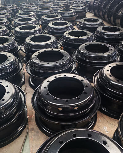
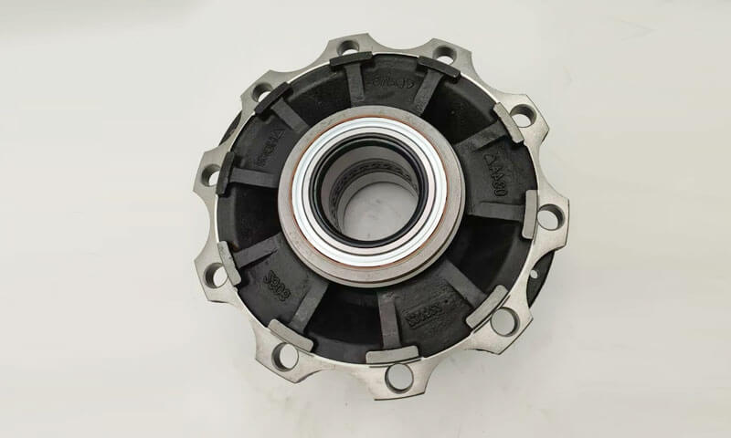
Typical products include flywheels, ブレーキディスク, belt pulleys, ホイールハブ, gear discs and brake drums.

All these parts share identical structural characteristics as axisymmetric rotary bodies: a thick central hub forming prominent hot spots, transitional connecting webs between hubs and outer rims, and thin-walled outer circumferential edges.

The drastic wall thickness disparity brings inherent metallurgical challenges, including shrinkage porosity concentrated inside hubs, end-face warpage deformation, thermal stress cracks, chilling tendency on thin sections, uneven circumferential hardness, slag inclusions and gas pores.

The core philosophy of process design lies in regulating solidification sequences via risers, chills and optimized gating layouts to realize directional solidification or proportional solidification on demand.

Sand casting has become the dominant manufacturing route for medium-to-large sized wheel & disc castings with small and medium batch production volumes due to its flexible tooling, low upfront investment and strong adaptability to varied geometries.

1. Structural Characteristics and Casting Challenges of Wheel and Disc Components

Wheel and disc castings are typical rotational structural components characterized by axisymmetric geometry, large differences in section thickness, and complex heat transfer behavior during solidification.

Although these components generally have relatively simple external shapes, their internal casting quality is highly dependent on the interaction between geometry, molten metal flow, および固化制御.

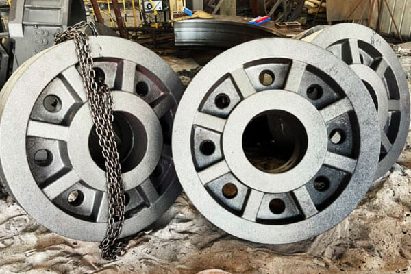
Wheel and disc castings

Typical Structural Characteristics of Wheel and Disc Castings

A wheel or disc casting can generally be divided into three functional regions: the hub, the disc/web section, and the outer rim.

The central hub is usually the thickest section and provides the connection point for shafts, ベアリング, ボルト, or transmission systems.

Because of its large volume and slow cooling rate, the hub becomes the main thermal hotspot during solidification.

Liquid metal in this region remains molten longer than surrounding areas, causing a high risk of shrinkage defects if sufficient feeding is not provided.

The disc or web section connects the hub with the outer rim and is responsible for transmitting mechanical loads while maintaining lightweight construction.

This region often contains gradual or curved thickness transitions. Improper transition design or uneven cooling can generate residual stresses, ねじれ, そして熱いひび割れ.

The outer rim typically has a smaller cross-sectional thickness and cools faster than the hub.

Excessive cooling of this area may cause premature solidification before the hub has completed feeding, leading to internal porosity and uneven mechanical properties.

The relationship between these three regions determines the overall casting behavior:

  • The hub tends to remain hot and requires effective feeding.
  • The disc requires balanced cooling to prevent deformation.
  • The rim requires controlled solidification to avoid premature freezing.

したがって, successful casting design must achieve a controlled thermal gradient from the outer regions toward the central feeding zone.

Major Casting Challenges of Wheel and Disc Components

Wheel and disc castings involve complex thermal behavior due to their typical structure of thick hubs, 薄いウェブ, and outer rims.

The large differences in section thickness create uneven solidification, feeding difficulties, and stress concentration.

The following table summarizes the major casting challenges and corresponding control methods.

キャスティングチャレンジ Cause and Mechanism Typical Defects or Risks Recommended Control Measures
Shrinkage Porosity in Hub Thermal Hot Spot The central hub has the largest section thickness and the longest solidification time. As surrounding areas freeze earlier, feeding channels may become blocked, preventing liquid metal compensation for solidification shrinkage. Internal shrinkage cavities, 微細気孔率, reduced fatigue strength, poor ultrasonic inspection results. Apply directional solidification design; optimize riser size and location; use insulated/exothermic risers, external chills, and proper pouring temperature control.
Uneven Cooling and Thermal Stress Formation Thin rim and web sections cool faster, while the thick hub remains hot for a longer period. Different cooling rates create thermal gradients and uneven contraction. 熱い亀裂, 残留応力, disc warping, loss of roundness, machining distortion, dynamic imbalance. Optimize casting orientation, mold rigidity, 冷却条件, and apply stress-relief heat treatment for precision components.
Incomplete Filling of Thin Disc and Web Sections
Thin sections lose heat rapidly during mold filling. If molten metal temperature decreases below the critical filling temperature, complete cavity filling becomes difficult. ミス, コールドシャット, incomplete edges, poor surface quality. Optimize gating location, filling velocity, 注ぐ温度, and use smooth low-turbulence filling systems such as ring-shaped side gating or bottom filling.
Gas Porosity and Non-Metallic Inclusions Turbulent molten metal flow causes air entrainment, 酸化, slag mixing, and mold erosion. Large pouring volumes increase inclusion risks. 噴気孔, subsurface porosity, oxide defects, slag inclusions, reduced fatigue performance. Use low-turbulence gating systems, セラミックフォームフィルター, effective slag removal, proper mold permeability, and stable pouring practices.
Dimensional Distortion and Machining Instability Uneven contraction during cooling causes internal stress accumulation. The hot hub restricts shrinkage of cooler rim sections. Flatness deviation, loss of concentricity, out-of-round conditions, excessive machining allowance. Improve cooling symmetry, optimize mold design, control shakeout timing, and perform stress-relief treatment when necessary.

2. Overall Process Layout & Parting Schemes

The process layout of 砂鋳造 wheel and disc components is a critical factor that determines filling behavior, 凝固シーケンス, 寸法精度, そして最終的なキャスティング品質.

Unlike simple-shaped castings, wheel components contain significant differences in section thickness between the central hub, disc/web, and outer rim, making the selection of casting orientation and parting method especially important.

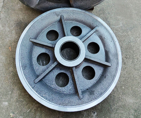
Pulleys Castings
Pulleys Castings

Horizontal Parting Process (The Most Common Solution)

Horizontal parting is the most widely used method for wheel and disc castings, 特に フライホイール, ブレーキディスク, pulley wheels, small and medium-sized hubs, and general industrial discs.

In this arrangement, the casting is positioned horizontally, and the parting plane is usually selected through the disc or web section.

The mold is divided into an upper cope and lower drag, allowing convenient pattern withdrawal, core installation, and mold assembly.

This method is widely compatible with both:

  • Green sand molding systems for mass production;
  • Resin bonded sand processes for medium and small batch production.

The main advantages of horizontal parting are its simple process layout, low tooling investment, and excellent production efficiency.

Core placement is relatively straightforward, making it suitable for components with central holes, 内部空洞, or shaft mounting structures.

Typical gating arrangements include:

  • Central top gating, where molten metal enters through the hub area and flows outward toward the rim;
  • Circumferential side gating, where molten metal enters evenly around the circumference to improve filling stability.

しかし, horizontal molding also has certain limitations. Because the upper and lower surfaces of the casting experience different heat transfer conditions, cooling is often asymmetric.

これにより、次のような結果が生じる可能性があります:

  • Uneven shrinkage;
  • End-face warpage;
  • 残留応力;
  • 寸法偏差.

加えて, the upper surface of the mold cavity has a higher tendency to trap gas and non-metallic inclusions, which may cause:

  • 噴気孔;
  • Slag inclusions;
  • 表面欠陥.

したがって, for precision-critical wheel components, horizontal parting often requires additional measures such as improved venting, 最適化されたゲート, 制御された冷却.

Vertical Parting and Vertical Pouring Process

The vertical parting process places the wheel or disc casting in a vertical orientation, with the mold split along the radial direction of the component.

This method is mainly used for high-precision wheel hubs, heavy-duty drive wheels, railway components, and large rotating parts requiring excellent dimensional stability.

Compared with horizontal molding, vertical casting provides a more symmetrical thermal environment.

The entire circumference of the casting experiences a more uniform cooling rate, which significantly reduces temperature differences between different regions.

The major benefits include:

  • Improved roundness and concentricity;
  • Reduced deformation after cooling;
  • More balanced microstructure distribution;
  • Lower residual stress.

Because the casting is positioned vertically, molten metal flow can also be better controlled, reducing the risk of uneven filling between upper and lower sections.

しかし, vertical parting requires more advanced molding capability. The main challenges include:

  • More complicated pattern and core design;
  • Higher mold assembly requirements;
  • Increased difficulty in handling large molds;
  • Greater requirements for lifting and positioning equipment.

したがって, this method is generally applied in resin sand production environments, particularly for medium-volume or customized heavy castings rather than high-volume automated production.

Inclined Pouring Process (Hybrid Optimization Method)

Inclined pouring is an improved process based on horizontal molding principles.

注ぐ途中, the mold is tilted at a controlled angle, 通常、周り 10°–25°, allowing molten metal to enter the cavity under more stable conditions.

This method combines the advantages of horizontal and vertical casting by improving both:

  • Filling smoothness;
  • Solidification direction control.

The inclined position reduces direct metal impact on the mold surface and decreases turbulence during filling.

同時に, it promotes a more favorable thermal gradient, helping molten metal feed toward the hub region.

Inclined pouring is particularly suitable for:

  • Ductile iron wheels;
  • Large disc castings;
  • Components with severe hub shrinkage tendency.

Its main benefits include:

  • Reduced oxide inclusion formation;
  • Improved hub feeding efficiency;
  • Lower risk of shrinkage porosity;
  • 寸法安定性の向上.

しかし, inclined pouring requires additional equipment or fixtures to control the mold angle accurately, making it more suitable for specialized production rather than standard molding lines.

3. Sand Mold Design and Manufacturing Process

The quality of sand molds directly determines the filling behavior, 表面の品質, 寸法精度, and internal soundness of wheel and disc castings.

Because these components typically combine 大径, thick hubs, thin web sections, and complex heat transfer conditions, the molding process must provide sufficient strength to maintain cavity stability while also maintaining good permeability and collapsibility.

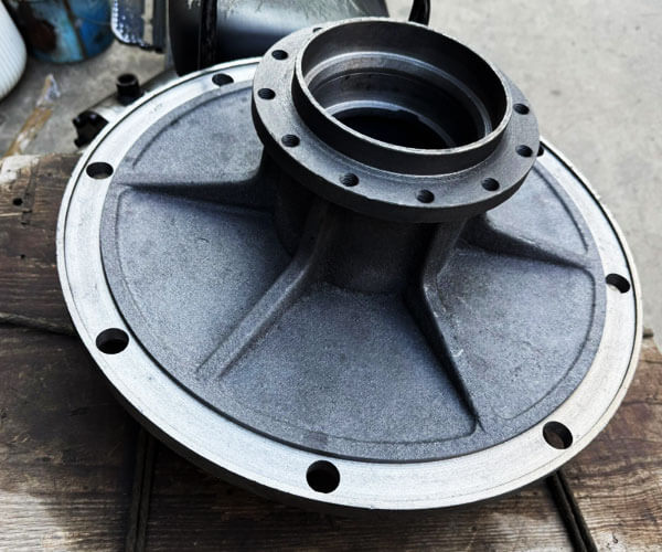
Gray cast-iron disc castings

Green Sand Molding for Mass Production of Small and Medium Wheel Components

Green sand molding is one of the most widely used and economical methods for producing small and medium-sized wheel and disc castings, のような:

  • Belt pulleys;
  • Small flywheels;
  • ブレーキドラム;
  • General industrial discs.

This process uses a mixture of silica sand, ベントナイト粘土, 水, and carbon additives to create a reusable molding material.

It is especially suitable for automated production lines where high productivity and low manufacturing cost are required.

The performance of green sand depends strongly on its physical properties. Typical control parameters include:

パラメーター 典型的な範囲 Influence on Casting Quality
水分含有量 3.2%–3.8% Controls mold strength, plasticity, and gas generation
Compactability 38%–45% Determines molding density and cavity stability
透過性 ≥80 Ensures effective gas escape during pouring
Green compressive strength 0.12–0.16 MPa Provides sufficient mold strength against metal pressure

The proportion of active bentonite and carbon additives must be carefully controlled. Bentonite provides bonding strength, while coal dust or similar carbonaceous additives help reduce:

  • 金属の貫通力;
  • 焼き付き欠陥;
  • 表面の粗さ;
  • Gas-related surface defects.

During production, reclaimed sand temperature must also be controlled. Hot reclaimed sand can negatively affect moisture distribution and reduce mold quality, leading to poor surface finish and dimensional instability.

For wheel and disc castings, additional venting measures are usually applied because gas tends to accumulate around the highest points of the hub and web sections.

Typical solutions include:

  • Annular vent grooves along the parting surface;
  • Gas vent holes at high points of the mold;
  • Additional vent risers above enclosed cavity areas.

しかし, green sand molding also has limitations. Because the mold has relatively low rigidity and moderate dimensional stability, typical dimensional accuracy is around CT9 – CT11 according to casting tolerance standards.

加えて, the relatively slow and uncontrolled cooling characteristics of green sand molds increase the risk of shrinkage defects in thick hub sections.

したがって, green sand is generally not preferred for heavy-duty ductile iron wheel hubs requiring strict ultrasonic inspection or high fatigue performance.

Self-Hardening Resin Sand Molding for Large and High-Performance Wheel Castings

For large wheel hubs, heavy-duty flywheels, railway components, and castings requiring strict non-destructive testing, self-hardening resin sand is the preferred molding technology.

緑の砂とは異なり, resin sand achieves mold strength through chemical bonding between resin and hardener, allowing the production of large and complex molds without external compaction equipment.

代表的な材料としては、:

  • 70/140 mesh silica sand;
  • Ceramsite sand for improved thermal stability;
  • Furan resin or alkaline phenolic resin systems.

The resin addition ratio is generally controlled within approximately 1.0%–1.4%, while the hardener dosage is adjusted according to:

  • 周囲温度;
  • Humidity;
  • Required curing speed;
  • Production cycle requirements.

Resin sand provides several important advantages for wheel and disc castings:

Improved Dimensional Accuracy

The high rigidity and stability of resin sand molds allow dimensional accuracy to reach approximately CT8–CT9, which is significantly better than conventional green sand molding.

This is particularly important for rotating components where dimensional deviation may affect:

  • Balance performance;
  • Shaft alignment;
  • 加工代;
  • 寿命.

Better Capability for Complex Cores

Large wheel castings often require internal cavities, mounting holes, or complex hub structures. Resin sand allows the production of:

  • Large core assemblies;
  • Thin and complex sand cores;
  • Accurate internal passages.

This makes it highly suitable for customized, single-piece, そして小ロット生産.

Higher Surface Quality

The smoother mold cavity surface reduces:

  • 砂の付着;
  • 表面の粗さ;
  • Cleaning workload;
  • 加工代.

しかし, resin sand also introduces certain challenges.

Because resin binders generate more gas during pouring, improper process control may cause:

  • Subsurface blowholes;
  • ガス気孔率;
  • Carbon-related defects.

加えて, resin sand molds have higher rigidity and lower collapsibility compared with green sand. For thick-section castings, restricted contraction may increase the risk of:

  • Thermal stress;
  • ホットクラッキング;
  • Residual stress concentration.

したがって, resin sand processes require careful coordination between mold strength, ライザーデザイン, and cooling control.

Mold Coating Technology

Mold coating plays an essential role in improving surface quality and preventing casting defects, especially for wheel and disc components with large hot sections and complex transitions.

The primary purpose of coatings is to create a protective barrier between molten metal and the sand mold, 削減:

  • Sand penetration;
  • Metal-mold reaction;
  • 焼き付き欠陥;
  • 表面の粗さ.

Different materials require different coating systems.

のために gray cast iron wheel castings, graphite-based coatings are commonly applied because graphite provides:

  • Good thermal stability;
  • Reduced metal penetration;
  • Improved surface finish.

のために ductile iron and thick-section castings, alcohol-based zircon powder coatings are generally preferred due to their:

  • 高耐火性;
  • Excellent resistance to molten iron erosion;
  • Strong protection at thermal hotspots.

A typical procedure includes:

  1. First coating application to cover the entire cavity surface;
  2. Complete drying to remove moisture;
  3. Second coating application for improved protection;
  4. Final inspection before mold assembly.

Insufficient drying may generate additional gas during pouring, while excessive coating thickness may reduce permeability and affect casting quality.

Venting System Design for Wheel and Disc Sand Molds

Gas management is a critical aspect of wheel and disc casting because their rotational geometry naturally creates gas accumulation zones.

A properly designed venting system typically includes:

Venting Measure Typical Design 関数
Parting surface vent grooves Annular grooves approximately 0.4 mm× 6 mm Provides gas escape channels along the mold interface
Hub vent rods φ8–12 mm vent holes or rods at the hub top Releases concentrated gas from thick sections
Core venting system Vent cords or porous channels inside sand cores Directs internal core gases outside the mold
Exhaust risers Located at high points of the casting Improves filling stability and prevents gas entrapment

Effective venting design must maintain a balance: insufficient venting causes gas defects, while excessive venting may weaken the mold or increase metal penetration risk.

4. Gating System Design for Wheel and Disc Castings

The gating system plays a decisive role in determining the internal quality, 寸法安定性, and mechanical performance of wheel and disc castings.

Due to their typical rotating geometry—with a massive hub, relatively thin web sections, and a thinner outer rim—the filling process must be carefully controlled to avoid turbulence, 酸化物同伴, コールドシャット, incomplete filling, and uneven temperature distribution.

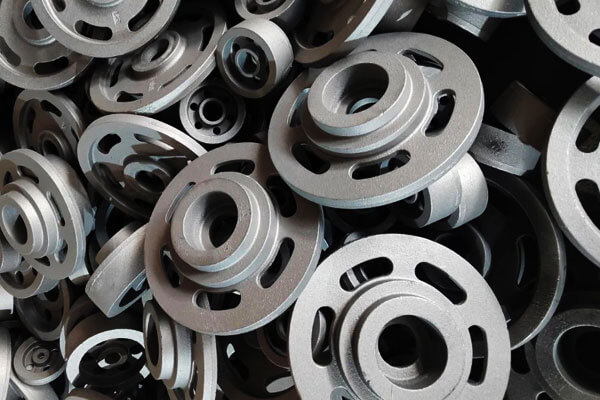
Disc Castings
Disc Castings

Central Top Gating System: Simple Layout with Strong Directional Solidification Capability

The central top gating system is one of the traditional solutions for flywheels and relatively simple disc-shaped castings.

このデザインでは, molten metal enters from the center hub area and flows radially outward toward the rim through the web section.

This arrangement provides a natural temperature gradient because the central hub remains hotter than the outer rim during filling and solidification.

When combined with properly designed risers, the system can promote directional solidification from the thinner outer sections toward the hub, allowing feeding of the central hot spot.

しかし, the central feeding position also creates several potential problems.

Continuous exposure of the hub region to high-temperature molten metal increases the thermal concentration of the hub, which may enlarge the hot spot and increase the risk of shrinkage cavities or microporosity.

加えて, direct impact of the metal stream at the center can generate turbulence during the initial filling stage, increasing the possibility of oxide film formation and slag entrainment.

For improved performance, modern designs often incorporate ceramic foam filters in the pouring basin, extend multiple radial ingates from the center, and adjust the flow direction to prevent direct metal impact on thin web areas. These modifications help reduce turbulence and improve internal cleanliness.

Annular Slit Side Gating System: Preferred Solution for Brake Discs and Precision Rotating Parts

For brake discs, ブレーキドラム, and other components requiring excellent dimensional accuracy and dynamic balance, annular slit side gating is widely considered one of the most effective solutions.

In this configuration, a circular runner is arranged around the hub area, with multiple narrow ingates evenly distributed along the circumference.

Molten metal enters the mold cavity simultaneously from multiple directions, producing a balanced filling pattern.

The major advantage of this system is its ability to achieve uniform temperature distribution around the entire circumference.

Since the molten metal reaches different regions of the casting at nearly the same time, thermal gradients are minimized, reducing residual stress, ねじれ, and roundness deviation.

The relatively gentle filling behavior also reduces turbulence compared with direct top pouring. Lower turbulence means less oxidation, fewer entrapped inclusions, and improved surface quality.

This makes the design particularly suitable for brake components where machining allowance is limited and dimensional stability is critical.

The annular gating system also supports more uniform solidification between the hub, web, and outer rim.

When combined with correctly positioned risers and chills, it can effectively control shrinkage defects in areas with significant wall thickness variation.

Bottom Gating System: High-Quality Filling for Heavy-Duty Wheel Hubs

For large and heavy wheel hubs, drive wheels, and high-load industrial components, bottom gating is often selected to achieve the highest possible filling quality.

In a bottom gating system, molten metal enters from the lower region of the mold cavity and rises gradually upward.

The metal surface remains relatively stable during filling, significantly reducing splashing, 空気のエントレインメント, and secondary oxidation.

The primary advantage of this method is its excellent flow control. Because the molten metal rises smoothly rather than falling vertically, the risk of turbulent flow and sand erosion is greatly reduced.

This is particularly important for large castings where even small amounts of oxide inclusions or sand particles can seriously affect fatigue performance.

しかし, bottom filling also has limitations. Since the upper areas of the casting are filled last, their temperature may decrease before complete feeding occurs.

したがって, bottom gating must be carefully combined with efficient riser systems, insulating sleeves, and external chills to maintain adequate feeding pressure and compensate for shrinkage in thick hub sections.

General Design Guidelines for Efficient Gating Systems

Regardless of the specific gating configuration, several fundamental principles should be followed during wheel and disc casting design.

A closed or semi-closed gating system is generally preferred because it reduces turbulence and improves slag separation.

The typical cross-sectional relationship between sprue, ランナー, and ingate is approximately:

Sprue : Runner : Ingate = 1 : 1.2 : 0.8–1

This ratio helps maintain stable metal velocity while avoiding excessive turbulence.

Horizontal runners should be extended beyond the last ingate to form slag collection zones, allowing impurities to remain away from the casting cavity.

Ceramic foam filters are frequently installed in the runner system to further improve melt cleanliness.

The ingate shape is also important. Fan-shaped, slit, or tangential ingates are often used for wheel and disc castings because they distribute molten metal gradually and reduce direct impact on mold surfaces.

最終的に, the most effective gating design is one that achieves スムーズな充填, controlled heat flow, and progressive solidification from thin sections toward feeding sources.

By optimizing the relationship between gating, ライザー, 寒気, および鋳造ジオメトリ, manufacturers can significantly reduce shrinkage porosity, インクルージョン, 変形, and other common defects in wheel and disc castings.

5. Feeding System Design: Risers and Chills

The feeding system is a critical factor in determining the internal quality of wheel and disc castings.

Due to their typical structure—large hubs, thinner webs, and outer rims—these components contain significant differences in section thickness.

凝固中, the thick hub area remains liquid longer and experiences greater volumetric shrinkage, making it highly susceptible to shrinkage cavities and microporosity.

Riser Design for Wheel and Disc Castings

The hub area is normally the main feeding target because it represents the largest thermal mass in the casting.

Risers are usually positioned above or close to the hub to provide liquid metal during the final stage of solidification.

のために gray cast iron wheel castings (EN-GJL-250, EN-GJL-300), directional solidification is commonly applied.

Cylindrical or oval risers are placed at hub hot spots, and their modulus is designed higher than the feeding zone to ensure that the riser freezes later than the casting.

のために ductile iron wheel castings (EN-GJS-450-10, EN-GJS-600-3), graphite expansion during eutectic solidification provides partial self-feeding capability.

したがって, excessive riser volume is avoided. Modern designs usually combine smaller insulated risers with chills to improve casting yield while maintaining internal soundness.

For heavy-duty wheel hubs with thick sections, insulated riser sleeves or exothermic risers are often used to extend feeding time and reduce shrinkage defects.

Chill Application and Solidification Control

Chills are used to accelerate local cooling and control the solidification pattern.

By increasing heat extraction in selected areas, chills reduce the size of hot spots and promote directional solidification toward the riser.

For wheel and disc castings, chills are mainly placed around:

  • Hub side walls where thermal concentration occurs.
  • Hub-to-web transition areas.
  • Local thick sections with high shrinkage risk.

しかし, chill placement must be carefully optimized. Excessive cooling at thin rim areas may cause premature solidification, resulting in misruns, コールドシャット, or uneven hardness.

したがって, chills are generally avoided in thin sections unless specific microstructure control is required.

The most effective feeding design is usually a combination of insulated risers and properly positioned chills, where chills control the heat flow while risers provide final shrinkage compensation.

Common Feeding Defects and Solutions

Improper feeding design can lead to several typical casting defects:

欠陥 Main Cause Optimization Method
ひけ巣 Insufficient liquid feeding at hub hot spots Increase riser efficiency or improve insulation
Microporosity Poor solidification direction and feeding pressure Optimize chills and temperature gradient
ホットクラッキング Excessive thermal stress between thick and thin sections Balance cooling rate and improve feeding layout
鋳造歩留まりが低い Oversized risers Optimize riser size through process simulation

6. 溶融, Nodularization and Inoculation Process for Ductile Iron Wheel Castings

Ductile iron is widely used for heavy-duty wheel and disc castings because it provides an excellent combination of strength, タフネス, 疲労抵抗, そして摩耗性能.

ねずみ鋳鉄との比較, ductile iron contains spherical graphite nodules, which significantly reduce stress concentration and improve mechanical properties.

しかし, achieving stable ductile iron quality requires precise control of melting, magnesium treatment, and inoculation processes.

Melting Process and Chemical Control

The melting process establishes the foundation for ductile iron quality.

Electric induction furnaces are commonly used because they provide accurate temperature and chemical composition control.

Typical ductile iron grades for wheel castings include:

  • EN-GJS-450-10
  • EN-GJS-600-3

A typical chemical composition range is:

要素 典型的な範囲 (%) 関数
炭素 (c) 3.5–3.8 グラファイト形成を促進します
シリコン (そして) 2.3-2.8 グラフィット化を強化します
マンガン (Mn) ≤0.4 Strengthens matrix
硫黄 (s) ≤0.025 Must be controlled before Mg treatment
リン (p) ≤0.03 Prevents embrittlement
マグネシウム (mg) 0.035–0.060 residual Forms spherical graphite

Typical temperature control:

  • Tapping temperature: 1500–1550℃
  • 注ぐ温度: 1360–1420°C

Strict control of sulfur and phosphorus is essential because excessive levels reduce nodularity and mechanical performance.

Magnesium Nodularization Treatment

Magnesium treatment is the key step that transforms graphite from flakes into spherical nodules. The most common method uses a magnesium-ferrosilicon alloy added to molten iron.

治療中, magnesium reacts with sulfur and oxygen, creating a strong reaction.

Proper control of treatment temperature, alloy addition, and magnesium recovery is necessary to obtain stable nodular graphite.

Poor nodularization may result in:

  • Vermicular graphite formation.
  • Reduced tensile strength and elongation.
  • 耐疲労性が低い.

A high-quality ductile iron structure should have:

  • High graphite nodularity.
  • Uniform graphite distribution.
  • Controlled nodule size.
  • Suitable ferritic/pearlitic matrix according to performance requirements.

Inoculation and Graphite Refinement

Inoculation improves graphite nucleation and stabilizes the final microstructure. It is normally performed in two stages: initial inoculation during tapping and secondary inoculation during pouring.

Ferrosilicon-based inoculants containing calcium, barium, or zirconium are commonly used.

Effective inoculation helps to:

  • Increase graphite nodule count.
  • Reduce carbide formation.
  • Improve mechanical properties.
  • Achieve uniform hardness distribution.

For large wheel castings, inoculation is especially important because slow cooling in sand molds can lead to coarse graphite and reduced strength.

7. シェイクアウト, Cooling and Heat Treatment Process

The shakeout, 冷却, and heat treatment stages play an important role in maintaining the dimensional accuracy, 機械的特性, and long-term service reliability of wheel and disc castings.

Although the casting process is completed after solidification, improper handling during cooling or premature removal from the mold can introduce residual stress, ねじれ, and even cracking, especially in components with large diameter, 不均一な壁の厚さ, and strict balance requirements.

Shakeout and Holding Time Control

After pouring and solidification, castings must remain inside the sand mold for a sufficient period before shakeout.

The sand mold provides thermal insulation and allows the casting to cool gradually, reducing temperature gradients between thick and thin sections.

Premature shakeout removes this thermal protection too early, causing uneven cooling and increasing the risk of:

  • Hub deformation caused by residual thermal stress.
  • Web distortion and loss of flatness.
  • Surface cracking in high-stress areas.

The required holding time depends mainly on casting size, 壁の厚さ, 材質の種類, and mold characteristics.

Typical holding times are:

キャストタイプ Recommended Holding Time
Small wheel and disc castings ≥ 30 分
Medium wheel hubs and flywheels 60–90 minutes
Large and heavy-duty wheel castings 90–120 minutes or longer

For large ductile iron wheels, extended cooling inside the mold is often preferred because slow cooling helps reduce thermal gradients and improves dimensional stability.

シェイクアウト後, castings should be handled carefully. Large wheel and disc castings should not be stacked or placed under uneven support, as their own weight can cause permanent bending deformation while the metal is still at elevated temperature.

Controlled Cooling After Shakeout

After removal from the mold, wheel and disc castings should continue cooling under controlled conditions.

迅速な冷却, especially for large-section ductile iron components, may generate excessive thermal stress between the hub and rim areas.

Proper cooling practice includes:

  • Avoiding forced cooling with water or strong air streams.
  • Allowing castings to cool naturally in a controlled environment.
  • Supporting castings evenly to prevent gravitational distortion.

For ductile iron wheels, controlled cooling also influences the final microstructure.

Slow cooling promotes graphite growth and reduces the formation of undesirable carbides, while excessive cooling rates may increase hardness and reduce toughness.

応力除去熱処理

Residual stress is generated during casting because different sections contract at different rates during cooling.

The thick hub, thin web, and outer rim experience different thermal contraction behaviors, resulting in internal stress even when no visible defects exist.

For high-precision wheel components, especially brake discs, drive wheels, and large hubs, stress relief annealing is commonly performed before machining.

A typical stress relief process involves:

  • Heating temperature: 500–550℃
  • 開催時間: determined by casting thickness and weight
  • Controlled furnace cooling to minimize new thermal stress

This treatment reduces residual stress and improves machining stability. Without stress relief, castings may deform during rough or finish machining because the removal of material releases internal stress.

8. 結論

Sand casting of wheel and disc components is a highly specialized process that requires careful coordination between mold design, gating technology, 給餌戦略, 冶金, and cooling control.

The key to producing high-quality wheel castings is not simply achieving complete filling, but controlling the entire thermal and fluid-flow process:

  • Selecting the correct casting orientation;
  • Designing stable and clean filling systems;
  • Managing hub thermal hotspots;
  • Applying effective risers and chills;
  • Controlling ductile iron metallurgy;
  • Using simulation-based optimization.

With properly engineered sand casting processes, manufacturers can produce large and complex wheel and disc castings with excellent mechanical properties, 寸法精度, and long-term service reliability for demanding industrial applications.

LangHe – Professional Custom Manufacturer of Wheel and Disc Castings in China

LangHe is a professional China manufacturer specializing in custom wheel and disc castings, providing high-quality casting solutions for industrial rotating components, including flywheels, ブレーキディスク, ホイールハブ, プーリー, gear discs, ブレーキドラム, and heavy-duty machinery parts.

With extensive experience in sand casting and resin sand casting technologies, LangHe supports customers from initial casting design and process optimization to production, 機械加工, 検査, and final delivery.

Custom Wheel Castings Manufacturers

LangHe manufactures wheel and disc castings in a wide range of materials, 含む gray cast iron, 延性鉄, 炭素鋼, 合金鋼, とステンレス鋼, meeting the requirements of automotive, 産業用具, エネルギー, 交通機関, and heavy machinery applications.

Through strict quality control, 高度な製造能力, and customized engineering support, LangHe delivers durable, 費用対効果, and application-specific casting solutions for customers worldwide.

As a trusted custom wheel and disc casting manufacturer in China, LangHe is committed to helping global customers achieve higher product reliability, optimized casting performance, and reduced manufacturing costs through professional casting expertise and continuous process innovation.

Contact us for custom precision castings.

コメントを残してください

メールアドレスは公開されません. 必要なフィールドにマークが付けられています *

一番上までスクロール

すぐに見積もりを取得

あなたの情報を入力してください。すぐにご連絡させていただきます.