1. Introduction
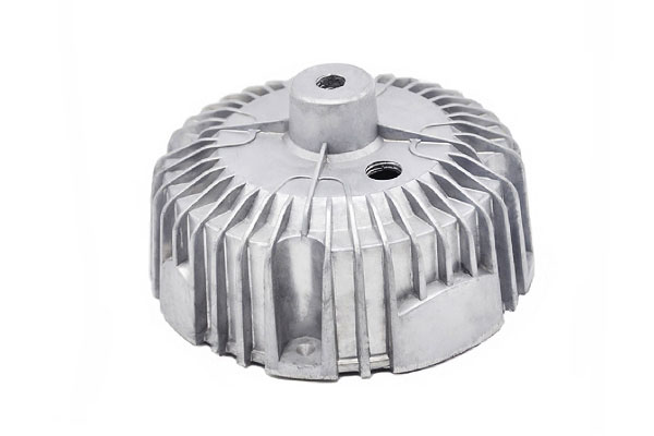
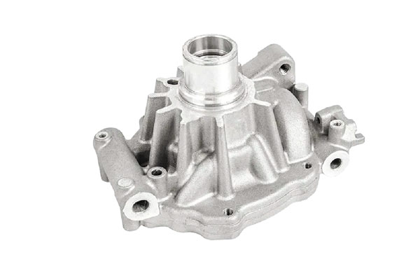
Aluminum die-casting covers are functional parts that protect internal mechanisms or electronics, provide mounting points, and often serve as part of the product’s heat-dissipation and electromagnetic shielding strategy.
Because covers are frequently produced at high volumes, die casting — especially high-pressure die casting (HPDC) — is the preferred route for combining tight tolerances, thin walls, complex ribs and bosses, and low per-part cost.
Getting reliable performance requires integrated consideration of alloy, casting method, design, tooling, post-process operations and QA.
2. What is a Custom Aluminum Die-Casting Cover?
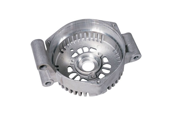
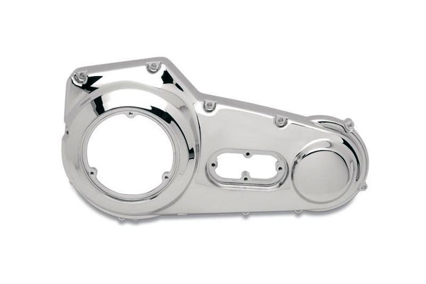
A custom aluminum die-casting cover is an engineered enclosure produced by forcing molten aluminum alloy into a steel die (mold) under controlled conditions to create a near-net-shape part that functions as a lid, housing, protective shield or heat-dissipation element.
“Custom” emphasizes design tailored to an application — geometry, bosses, ribs, sealing faces and finish are all optimized for the product’s functional, aesthetic and manufacturing requirements.
Unlike stamped, machined or sheet-metal covers, die-cast covers can integrate complex internal passages, threaded bosses, fine ribs and thin walls in a single piece.
This capability reduces assembly steps (fewer welds/screws), improves repeatability, and lowers per-part cost at volume.
Primary functional roles
Typical roles a die-casting cover performs:
- Environmental protection — dust/water sealing (with gasket or O-ring grooves) to achieve IP ratings (e.g., IP65/67 when properly sealed).
- Structural enclosure — provides mounting interfaces, locators and stiffness for internal components.
- Thermal management — spreads heat and provides finned surfaces when the cover is used as a heat sink for electronics or LED modules.
- EMI/RFI shielding — conductive housing or mating face providing electromagnetic compatibility when plated or properly gasketed.
- Aesthetics & ergonomics — visible outer skin with controlled texture, paint or coating for consumer products.
- Serviceability — designed for repeated assembly/disassembly: threaded inserts, captive fasteners, serviceable seals.
3. Die-Casting Processes Suitable for Aluminum Covers
Selecting the right casting process for an aluminum cover strongly affects cost, integrity, surface quality and performance.
High-Pressure Die Casting (HPDC — cold-chamber)
When to use it: high volumes, thin-wall covers (typical walls 1.0–4.0 mm), many integrated ribs/bosses, good dimensional control and low per-part cost after tooling payback.
Why chosen: fastest cycles, excellent dimensional repeatability, very good surface finish as-cast, supports complex features and rapid automation.
Typical process parameters (engineering guidance):
- Melting temperature (furnace): ~690–740 °C.
- Shot sleeve / ladle temp (cold-chamber pour): ~650–700 °C.
- Die (mold) temperature: ~150–300 °C (depends on alloy, finish, cycle).
- Injection / intensification pressure: broadly 50–200 MPa (process/target thinness dependent).
- Cycle time: seconds to 1–2 minutes depending on part mass and cooling.
Advantages
- Thin walls, tight tolerances (typical as-cast ±0.1–0.5 mm), excellent surface finish (textured or polished dies).
- Highly automated; low cycle cost at medium-to-high volumes (thousands → millions).
- Good for covers requiring cosmetic outer skin + integrated mounting features.
Limitations
- Porosity risk (gas + shrinkage) unless controlled — may be unacceptable for pressure-sealed covers without process enhancements.
- Die tooling is expensive and complex (slides, cores, cooling), especially with undercuts.
- Some alloys (very high Mg) can be challenging; cold-chamber is used because aluminum attacks hot-chamber components.
Alloys: A380 / ADC12 / AlSi9Cu3(Fe) family are standard. Good fluidity and low hot-tearing tendency.
Practical tips
- Use ceramic filtration, controlled ladle transfer and degassing.
- Consider vacuum-assist (see 4.2) if sealing/pressure integrity needed.
- Design with uniform sections, generous fillets and readily machinable sealing faces.
Vacuum-Assist HPDC (Vacuum Die Casting)
When to use it: covers that must be leak-tight or have very low internal porosity (electronic enclosures, pressure-sealed housings), while still needing HPDC throughput and geometry.
What changes vs standard HPDC
- A vacuum system draws air/gas from the die cavity during or just before fill.
- Significantly reduces entrapped air and hydrogen porosity; improves mechanical properties and pressure tightness.
Benefits
- Lower internal porosity → better fatigue and sealing performance.
- Often eliminates need for impregnation or extensive rework for small leaks.
Tradeoffs
- Increased equipment cost and cycle complexity; slightly slower cycle rates due to vacuum steps.
- Requires careful die sealing and vacuum control.
Use case: HD electronic covers requiring IP67 sealing with machined gasket faces.
Low-Pressure Die Casting (LPC) / Gravity-assisted Pressure Fill
When to use it: larger covers, thicker sections, or parts where internal soundness is critical but HPDC geometry/throughput is less important.
How it works: molten metal is pushed into the mold from below using a small positive pressure (not shot) — fill is slower and calmer.
Typical pressure band:0.02–0.2 MPa (0.2–2 bar) — process-dependent and much lower than HPDC intensification pressures.
Advantages
- Calmer fill → less turbulence and oxide entrapment; better feeding → fewer shrinkage defects.
- Good for medium-to-large parts where porosity must be minimized (pump housings, larger covers).
- Easier directional solidification control.
Limitations
- Slower cycles and higher equipment/operation costs per part vs HPDC.
- Less suitable for very thin-wall, high-volume parts.
Alloys: A356/AlSi9 variants often used; suitable for thicker, heat-treatable designs.
Squeeze Casting / Semi-Solid (Thixo / Rheo) Casting
When to use it: performance covers where superior mechanical properties, low porosity and near-forged behavior are required (e.g., powertrain covers under high mechanical loads).
Principle: semi-solid slurry or direct squeeze under pressure during solidification collapses shrinkage and yields very low porosity.
Typical pressure during solidification: moderate static pressures — often tens of MPa applied while metal solidifies (process dependent).
Advantages
- Very low porosity, improved mechanical properties and fatigue life (approaching wrought/forged).
- Good for structural covers subject to dynamic loads.
Limitations
- Higher per-part cost; tooling and process control more demanding.
- Lower throughput vs HPDC; suited for medium volumes where performance outweighs cost.
Lost-Foam Casting (LFC) & Shell / Investment for Aluminum Covers
When to consider
- Lost-foam: complex internal cavities without cores — medium complexity and volume. Surface finish ~3.2–6.3 µm.
- Shell / Investment: when very fine detail and better surface finish are required but volumes are moderate (often less common for aluminum than for other alloys).
Advantages
- LFC lets you create internal channels without multiple cores; investment gives superior finish for visible parts.
- Useful for prototypes and low-to-medium volume production where tooling cost for HPDC is not justified.
Limitations
- LFC can have higher porosity than vacuum HPDC unless process controlled.
- Investment casting for aluminum is less typical; often used for specialty geometries or when thin, precise walls are required at modest volumes.
Process Selection Matrix — Quick Decision Guide
Use this condensed matrix to pick a process based on primary drivers.
- Highest volume, thin-wall covers, low per-part cost: HPDC (cold-chamber)
- High volume + sealing/low porosity required: Vacuum-assist HPDC
- Large, thicker covers needing low porosity (structural): Low-Pressure Casting
- Performance covers needing forged-like properties: Squeeze / Semi-Solid
- Complex internal cavities at low/medium volumes: Lost-Foam / Investment / Shell Casting
- Prototype / low volume, minimal tooling cost: sand casting or CNC machining may be better alternatives
4. Material Choices for Aluminum Die-Cast Covers
Common die-casting alloys (practical list)
- Al-Si-Cu (A380 / AlSi9Cu3(Fe)) — the most common HPDC alloy worldwide: excellent fluidity, good mechanical strength, and good castability for thin walls and complex shapes.
- Al-Si (A413/A413.0, A356 variants) — used for gravity/low-pressure or squeeze casting when higher ductility or heat-treatment capability is required (note: many of these are gravity/permanent-mold alloys rather than HPDC).
- ADC12 (JIS) — Japanese die-casting standard similar to A380/A383; common in Asia.
- High-silicon Al-Si alloys (AlSi12, AlSi10Mg) — higher fluidity and thermal stability; some used in gravity and precision casting.
- Die-casting specific Al-Zn/Mg alloys — less common for covers because of corrosion concerns unless coated.
5. Design for Die Casting — Geometry Rules for Covers
Design rules must balance function, castability and cost.

Key recommendations:
Wall thickness
- Target 1.5–4.0 mm for HPDC covers; minimum practical ~1.0–1.2 mm in select ribs/areas with expert gating and high flow. Avoid sudden thickness changes; use stepped transitions with fillets.
Draft
- Use draft angles 0.5°–3°: typical external faces 1–2°, internal undercuts may require cores or slides.
Ribs & bosses
- Ribs: height typically ≤ 2.5–3× wall thickness; rib thickness ≤ 0.6× nominal wall to avoid sink. Add generous fillets at rib bases (~1–2× thickness).
- Bosses: use boss reinforcement with radial ribs, core out boss center to avoid shrinkage. Ensure bosses have enough draft and an internal core where threaded inserts are planned.
Threads & inserts
- Avoid casting functional threads where possible; prefer machined threads or threaded inserts (helicoil, PEM, self-clinching inserts). For thin bosses, use inserts installed post-cast (spin-in, press-in).
Sealing faces & mating surfaces
- Reserve sealing faces for secondary machining to Ra targets and flatness; design “machining windows” and call out tolerances.
Undercuts & slides
- Minimize undercuts; where required use side-action slides or cores; every slide increases tooling complexity and cost.
Gating, venting & feed design
- Coordinate with foundry: place gates to promote laminar fill, avoid impingement on critical thin walls, provide vents near cores and internal cavities.
Thermal management
- For covers acting as heat sinks, maximize surface area (fins) but design fins with draft and spacing to allow demolding and post-casting cleaning.
Tolerance & datum plan
- Specify datums for machined features; typical die-casting tolerances: ±0.1–0.5 mm depending on feature size, tighter only after machining.
6. Tooling & Mold Considerations
Tool steel & life
- Use H13 or equivalent hot-work tool steels for HPDC dies; cooling channels and surface treatments (nitriding, PVD on ejector pins) improve life.
Typical die life: hundreds of thousands to several million shots depending on cycle parameters and maintenance.
Cooling & thermal control
- Uniform cooling reduces shrinkage and distortion. Design conformal cooling where possible; maintain die temperatures within 150–300 °C for aluminum.
Venting & filtration
- Effective venting reduces blowholes; ceramic in-line filtration in the pouring system removes oxides and inclusions.
Cores, slides and inserts
- Complex covers may need movable slides or collapsible cores; these increase initial tooling cost and maintenance but enable complex geometry without secondary assembly.
Ejector system & part handling
- Design ejector layout to avoid scuffing; use stripper plates or air-blow off for delicate features.
Die maintenance
- Include die protection, regular polishing, and a maintenance plan in the supplier contract to preserve surface finish and dimensional fidelity.
7. Process Parameters & Quality Controls — Typical Ranges
Melt & pour parameters (typical HPDC window)
- Melting temperature (Furnace): ~690–740 °C (alloy and practice dependent).
- Shot chamber temperature (cold-chamber): metal poured into shot sleeve typically 650–700 °C.
- Die temperature:150–300 °C (depending on alloy, cycle & finish).
- Injection pressure:50–200 MPa (higher for thin walls and fast fill).
- Cycle time: seconds to a minute depending on part and cooling requirements.
Quality controls
- Filtration: ceramic filters in ladle transfer.
- Vacuum assist / low pressure: where low porosity required.
- Porosity control & measurement: X-ray (radiography), ultrasonic inspection, or CT for critical parts.
- Process monitoring: shot profile, plunger speed, die temperature logged per cycle for SPC.
Defect drivers
- Gas porosity (hydrogen, entrapped air) — mitigated by degassing and vacuum.
- Shrinkage porosity — mitigated by gating, risering, and die thermal control.
- Cold shuts, misruns — caused by low melt temp or poor gating.
- Hot tearing — caused by restraint during solidification (addressed via geometry and controlled cooling).
- Oxide inclusions — minimized by filtration and calm filling.
8. Post-Casting Operations: Machining, Sealing Features, Inserts & Coatings
Secondary machining
- Machining critical faces, threads and mounting bosses is standard. Typical allowances: 0.5–2.0 mm depending on casting process; investment/shell may allow smaller.
Sealing & gaskets
- For IP-rated covers, machine sealing faces and provide gasket grooves (design per gasket spec).
Use flatness and Ra targets compatible with the gasket (e.g., Ra ≤ 1.6 μm for many rubber gaskets).
Threaded inserts & fasteners
- Options: press-fit brass/steel inserts, helicoils, PEM fasteners, self-tapping screws (if allowed). For repeated assembly cycles, use metal inserts rather than cast threads.
Coatings & surface finishing
- Anodizing is generally not applicable to die-cast Al because some alloys and porosity complicate anodize quality; electroless nickel plating, powder coating, liquid painting, or conversion coatings (e.g., chromate or non-chromate passivation) are common.
- Shot-peening / vibratory finishing for edges and aesthetics; electropolish where needed for smoothness (rare for aluminum).
- Sealing / impregnation for porosity is rarely used for aluminum (more common for cast iron), but epoxy impregnation can be applied for leak critical small castings.
EMI/RFI shielding
- For covers serving as electromagnetic shields, ensure continuous conductive contact at seams (conductive gaskets, plated mating faces) and consider conductive coatings.
9. Mechanical, Thermal & Electrical Performance — Practical Data
Useful engineering numbers (rounded):
- Density: 2.70 kg·L⁻¹ (≈2.70 g·cm⁻³).
- Elastic modulus: 69–72 GPa.
- Thermal conductivity: 120–170 W·m⁻¹·K⁻¹ (alloy/porosity dependent).
- Coefficient of thermal expansion (20–100 °C): 22–24 ×10⁻⁶ /°C.
- Electrical resistivity (room T): ~2.6–3.0 × 10⁻⁸ Ω·m (good conductor).
- Typical static strength (A380 or similar, as-cast): UTS ~200–320 MPa, yield ~100–200 MPa, elongation ~1–6% — dependent on section, porosity and post-processing.
- Fatigue & impact: cast aluminum has lower fatigue endurance than wrought aluminum; avoid tensile stress concentrations and require radiographic inspection for cyclic applications.
Design implications
- For heat-dissipation covers, aluminum’s conductivity is advantageous but surface area and contact resistance matter.
Use thicker sections where heat spreads or design fins with adequate wall thickness and draft. - For EMI shielding, ensure plating or continuous conductive mating surfaces; porous die castings may need plating for conductivity continuity.
- For mechanical load-bearing covers, check local stress concentrations at mounting bosses; use inserts if repeated torque or fatigue loads expected.
10. Inspection, Testing & Common Defects
Inspection methods
- Visual inspection: surface finish, flash, cold shuts.
- Dimensional inspection: CMM for critical features; go/no-go gauges for threads and bosses.
- Radiography (X-ray) / CT: detect internal porosity, shrinkage. Specify acceptance class.
- Ultrasonic testing (UT): thickness and subsurface defects.
- Leak testing / pressure testing: if cover seals a pressure cavity; use hydrostatic or pressure decay tests.
- Mechanical testing: tensile and hardness on coupons or witness samples per heat/lot.
Common defects & remedies
- Porosity / gas pockets: improve degassing, vacuum, gating, and use filtration.
- Cold shuts / flow lines: increase melt temp, revise gating or increase shot speed.
- Hot tearing: modify geometry (fillets), adjust gate placement or die thermal control.
- Surface burn/oxidation: improve plunger and transfer methods, use protective flux and skimming.
Acceptance criteria
- Define radiographic acceptance level (e.g., ISO 10049/ASTM). For pressure parts specify maximum porosity size/count and require 100% radiography or statistical sampling depending on risk.
11. Manufacturing Economics, Lead Time & Scale Decisions
Cost drivers
- Tooling: primary upfront cost; shell/investment higher than conventional steel die work. Complexity (slides, cores) increases cost.
- Cycle time / production rate: HPDC provides low per-part cost at high volumes.
- Secondary operations: machining, plating, coatings and assembly add unit costs.
- Quality and yield: porosity rejects, rework and scrap reduce yield.
Lead time
- Tooling design & manufacture: 4–12+ weeks depending on complexity and shop capacity.
- Prototype runs: add 2–6 weeks.
- Mass production: per-part cycle times measured in seconds to a few minutes; throughput depends on machine size and number.
When to choose die casting vs alternatives
- Die casting ideal: volumes from a few thousand units/year upward for moderately complex parts.
- Low volume / rapid prototyping: 3D-printed patterns + sand casting or CNC machining may be more cost effective.
- Very high structural/fatigue demand: consider machined or forged housings despite higher per-part cost.
12. Applications of Aluminum Die Casting Covers
Custom die-cast covers are widely used across industries:

- Consumer & industrial electronics: ECU lids, junction box covers, power supply enclosures.
- Automotive & mobility: sensor housings, electronic module covers, actuator lids.
- Lighting & thermal: LED luminaire covers with integrated fins and mounting bosses.
- Tools & small machinery: gearcase lids, gearbox covers, power-tool housings.
- Hydraulics & pumps: pump volute covers or bearing housings where integrated features reduce assembly.
- Telecom & RF: chassis lids providing EMI shielding with plated mating surfaces.
13. Sustainability, Recyclability & Life-Cycle Considerations
- Aluminum recycling: aluminum is highly recyclable and die-casting scrap and end-of-life covers have strong scrap value.
Recycled aluminum reduces embodied energy dramatically vs primary aluminum. - Design for disassembly: prefer mechanical fasteners or serviceable seals to allow reuse and recycling.
- Coating & contamination: avoid coatings that hamper recycling or heavy plating that complicates scrap streams. Specify recyclable paint systems and easily removable labels.
- Lifecycle cost: aluminum’s low weight can reduce shipping and operational energy (especially in vehicles), offsetting higher material cost.
14. Custom Aluminum Die Casting Cover vs. Alternatives
Below is a concise, engineering-oriented comparison table that contrasts a Custom Aluminum Die-Casting Cover with common alternatives.
Values are typical engineering ranges (rounded) to help decision-making — always confirm with your supplier/foundry for a given alloy/process and part geometry.
| Method / Material | Advantages | Limitations / Considerations | Typical wall thickness (mm) | Typical dimensional tolerance |
| Custom Aluminum Die-Casting (HPDC, A380/ADC12) | Complex geometry with ribs/bosses; high production efficiency; good thermal & EMI behavior; smooth as-cast surface | High tooling cost; porosity risk; anodizing/finishing constraints | 1.0–4.0 | ±0.1 → ±0.5 mm |
| Stamped / Formed Sheet-Aluminum | Low tooling cost for simple shapes; lightweight; fast turnaround | Limited 3D complexity; requires welding or assembly; lower stiffness | 0.5–3.0 | ±0.2 → ±1.0 mm |
| CNC Machined Aluminum (6061/6000 series) | Excellent precision and finish; no porosity; high structural integrity | High machining cost; long cycle time for volume production | ≥2.0 (design-dependent) | ±0.01 → ±0.1 mm |
Injection-Molded Plastic (ABS/PC/Nylon) |
Lowest part cost at high volumes; excellent cosmetics; corrosion-free; lightweight | Limited strength; poor heat/EMI performance; not suitable for high-load covers | 0.8–3.0 | ±0.1 → ±0.5 mm |
| Die-Cast Zinc (Zamak Series) | Excellent detail replication; high dimensional accuracy; low die wear | Heavier than aluminum; lower temperature capability; corrosion concerns | 1.0–4.0 | ±0.05 → ±0.3 mm |
| Cast/Forged Magnesium (Mg Alloys) | Extremely lightweight; good stiffness-to-weight ratio; die-castable | Higher cost; corrosion sensitivity; coating requirements; process controls needed | 1.0–4.0 | ±0.1 → ±0.5 mm |
| Forged / Machined Aluminum (Wrought 6xxx) | High mechanical strength; excellent fatigue performance; very low defect rate | Very high cost for complex shapes; more waste material | ≥3.0 | ±0.01 → ±0.1 mm |
15. Supplier & Procurement Checklist — What to Require from a Foundry
Contractual minimums
- Material & alloy designation (e.g., A380 per ASTM / ADC12 per JIS) and CMTR per EN 10204 type 3.1 or equivalent.
- Die & process details: HPDC machine size, vacuum/degassing, filtration used.
- Tooling & maintenance: die steel grade, expected die life, maintenance schedule.
- Dimensional & finish specs: CMM plan, Ra targets, datum references and machining allowances.
- NDT & sample plan: radiography %, UT plan, pressure/leak tests for sealed covers.
- Mechanical test results: tensile, hardness on representative coupons.
- Surface treatment certifications: plating thickness, coating adhesion, salt spray results if corrosion protection required.
- Traceability & marking: heat/lot marking and linkage to CMTR and inspection reports.
- Quality system & audits: ISO 9001 / IATF 16949 (automotive) evidence if relevant.
- Packaging & handling: corrosion-inhibiting packaging for export shipments.
Acceptance language example
“Parts shall be produced in alloy A380 per [spec], supplied with CMTR for each heat,
with 100% visual inspection, dimensional CMM report for first article, radiographic inspection per level X for production lot sample, and hydrostatic/pressure test at 1.25× working pressure for sealed housings.”
16. Conclusion
Custom aluminum die-casting covers offer a cost-effective way to produce robust, thermally capable and dimensionally accurate enclosures when the design is tuned for casting and the supplier process controls are robust.
Success rests on integrated decisions: pick a die-cast-suitable alloy, design for consistent wall sections and tooling demoldability, choose appropriate casting and degassing strategies (vacuum/filtration when sealing matters), machine critical faces, and require clear QA (CMTR, NDT, dimensional control).
With these elements in place, die-cast covers deliver excellent value, repeatability and lifecycle benefits — particularly at medium to high production volumes.
FAQs
What wall thickness should I specify for a die-cast cover?
Typical HPDC practice is 1.5–4.0 mm for main walls. Use thicker sections for load paths and heat spreading; avoid sudden changes in thickness.
Coordinate with the foundry for minimum thickness on complex ribs or deep draw features.
Which aluminum alloy is best for a sealed, waterproof cover?
A380 (ADC12 class) via vacuum-assisted HPDC is a common choice; use vacuum casting, ceramic filtration and controlled gating to minimize porosity.
Post-machining sealing faces and using a bonded gasket are crucial. For superior corrosion resistance or heat treatment needs, consider alternative alloys or coatings.
How tight are die-casting tolerances?
Typical as-cast tolerances for die-cast parts are on the order of ±0.1–0.5 mm depending on feature size and location.
Machined features can achieve much tighter tolerances — specify which faces will be machined.
Do I need to anodize die-cast aluminum covers?
Anodizing on die-cast alloys is tricky due to alloy composition and porosity; conversion coatings, e-coats or powder coatings are more commonly used.
If anodize is required, discuss alloy selection and sealing processes with the finisher.
How do I minimize porosity for a pressure-tight cover?
Employ vacuum die casting or low-pressure casting, use ceramic filtration and proper degassing, design directional solidification and risering, and apply radiographic inspection to validate internal soundness.