1. Introduction
Brackets are ubiquitous components that locate and support assemblies, transmit loads and serve as attachment points for sub-systems.
Die-casting enables highly integrated bracket geometries (ribs, bosses, internal cavities, integral clips) that reduce parts count and assembly time.
Aluminum die casting, in particular, is favored where weight reduction, corrosion resistance, electrical/thermal conductance and volume economics are priorities.
The engineering challenge is balancing geometry and production economics while ensuring the required static and fatigue performance.
2. What are Aluminum Die Casting Brackets?
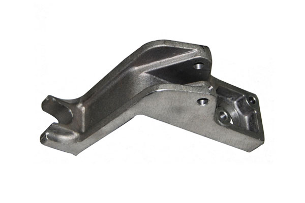
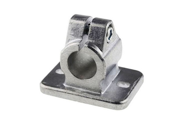
An aluminum die-casting bracket is a component produced by forcing molten aluminum into a reusable steel mold (die) under controlled conditions to form a near-net shape bracket.
Brackets produced by die casting typically need minimal secondary processing except for critical machined features.
They are used as mounting points, supports, housings and interface components in a wide span of industries.

Key defining attributes:
- Near-net shape complexity (integrated ribs, bosses, clips)
- Thin-wall capability (enables weight reduction)
- Repeatable dimensional control for high-volume production
- Tradeoff between as-cast porosity and attainable mechanical performance
3. Manufacturing Processes that Make Aluminum Die-Casting Brackets
The choice of casting process determines a bracket’s achievable geometry, mechanical integrity, surface quality, unit cost and production rhythm.
High-Pressure Die Casting (HPDC)
What HPDC is: Molten aluminum is forced into a steel die at high velocity and high pressure using a plunger or piston.
The metal solidifies against the die surfaces and the part is ejected, trimmed and (if required) machined.

Typical process parameters (engineering ranges):
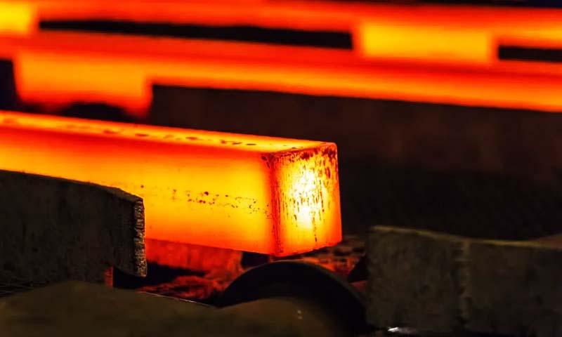
- Melt temperature: ~650–720 °C (depends on alloy and practice)
- Die operating temperature: ~150–250 °C (surface finish and texture dependent)
- Injection/shot speed: ~10–60 m/s (profiled)
- Cavity/holding pressure: ~40–150 MPa (machine and part dependent)
- Typical cycle time: ~10–60 s per shot (very short for thin parts; cooling dominates)
- Typical as-cast wall thickness: 1.0–5.0 mm (optimal 1.5–4.0 mm)
Strengths
- Extremely high throughput and repeatability for large volumes.
- Excellent surface finish and dimensional control (often minimal post-machining required beyond critical datum faces).
- Ability to produce very thin walls and complex integrated features (clips, ribs, bosses).
Limitations / risks
- Entrapped gas and shrinkage porosity are common if gating, die temperature, melt cleanliness or shot profiles are suboptimal.
- High initial tooling cost (hardened steel dies) and significant die-engineering lead time.
- Thick sections (>5–6 mm) are prone to shrinkage defects and require special design features (coring, feeders) or alternative processes.
When to use
- Complex, thin-walled brackets produced at medium to high annual volumes (typically thousands to millions of units).
Low-Pressure, Semi-Pressure and Vacuum-Assisted Variants
Low/Semi-pressure casting
- Metal is fed into the die by applying relatively low, controlled pressure at the furnace or runner (typical range 0.03–0.3 MPa). Filling is slower and gentler than HPDC.
- Produces castings with lower porosity and better feeding of thicker sections; cycle times are longer.
Vacuum-assisted HPDC
- A vacuum pump evacuates air from the die or runner system before/during filling.
- Benefits: greatly reduced entrapped-air porosity, improved mechanical consistency, fewer blowholes and improved weldability.
- Often combined with controlled shot profiles and melt degassing for structural brackets.
Practical implications
- These hybrid approaches are chosen when bracket integrity (especially fatigue performance) is important but HPDC geometry or productivity still desired.
They increase capital/process complexity and add per-part cost versus conventional HPDC, but can substantially improve usable mechanical properties.
Gravity (Permanent-Mold) and Low-Pressure Die Casting (LPDC)
Gravity / permanent-mold casting
- Molten metal pours into a reusable metal mold under gravity. Cooling is slower; feeding and gating are passive.
- Produces denser parts with lower gas porosity compared to standard HPDC.
- Typical cycle times: ~30–120 s (longer than HPDC).
- Better suited to moderately complex brackets with thicker sections or where lower porosity is required, but not ideal for very thin walls.
Low-pressure die casting (LPDC) (distinct from low-pressure filling described earlier)
- A pressure (typically tens to hundreds of millibars up to ~0.3 MPa) is applied from the bottom to push metal into the die; slower, laminar filling reduces turbulence and gas entrapment.
- LPDC achieves a better combination of density and geometry than gravity casting and is frequently used for structural brackets that need improved fatigue life.
When to choose
- Medium-volume production where part integrity and lower porosity are prioritized over the absolute cycle speed of HPDC.
Squeeze Casting and Semi-Solid (Thixo) Processing
Squeeze casting
- Molten metal is poured into a closed die and then compressed (squeezed) while solidifying. This pressure during solidification fills feeding channels and closes shrinkage pores.
- Produces near-forged density and mechanical properties with very low porosity, often approaching wrought-like performance.
Semi-solid / thixotropic processing
- Metal is cast in a semi-solid slurry state, which combines solid fragments and liquid so flow is more laminar and less turbulent, minimizing porosity and oxide entrainment.
- Allows complicated shapes with improved mechanical properties compared with conventional HPDC.
Tradeoffs
- Higher equipment and process cost, longer cycle times and more challenging process control than HPDC.
- Used when bracket duty cycles require the highest possible integrity (safety mounts, structural members, crash-relevant brackets).
Process Selection Guidance Summary
| Objective / Constraint | Preferred process |
| Very high volume, thin walls, complex features | HPDC |
| Need reduced gas porosity for improved fatigue | Vacuum-assisted HPDC or LPDC |
| Thick sections, lower porosity, medium volumes | Gravity / Permanent-mold |
| Highest strength / near-forged density | Squeeze casting / semi-solid |
| Moderate volumes with better integrity than HPDC | Low-pressure / semi-pressure |
4. Material Selection for Aluminum Die Casting Brackets
Typical alloys and application guidance
| Alloy (common name) | Typical use |
| A380 / ADC12 (HPDC workhorse) | General-purpose brackets — excellent castability, machinability, balanced strength. |
| A360 / similar | Improved corrosion and elevated-temperature performance. |
| A383 | Better fluidity for very thin or highly complex geometries. |
| A356 (cast-wrought, heat-treatable) | Used when higher ductility or heat treatment (T6) is required; more common in low-pressure or permanent-mold castings. |
Representative material properties (typical, process dependent)
Values vary with alloy chemistry, melt practice, porosity and post-processing. Use these as engineering starting points; validate by test coupons and production sampling.
- Density: ≈ 2.72–2.80 g/cm³
- Modulus of elasticity: ≈ 68–71 GPa
- A380 (as-cast typical): UTS ≈ 280–340 MPa, yield ≈ 140–180 MPa, elongation ≈ 1–4%
- A356 (T6 typical, heat-treated): UTS ≈ 260–320 MPa, yield ≈ 200–240 MPa, elongation ≈ 6–12%
- Thermal conductivity (alloyed castings): typical 100–150 W/m·K (alloy and porosity dependent)
- Hardness (as-cast): ~60–95 HB (varies by alloy and heat condition)
Design implication: If bracket function demands higher ductility/fatigue performance or elevated temperature strength, select heat-treatable alloys or an alternative process that reduces porosity.
5. Design for Die Casting: Geometric Rules for Brackets
Wall thicknesses
- Target range:1.0–5.0 mm, with 1.5–4.0 mm being the practical sweet spot for many HPDC brackets.
- Keep walls as uniform as possible. When thick sections are unavoidable, use local coring or ribs to reduce mass and shrinkage.
Draft, fillets and corners
- Draft angles: external 0.5°–2°, internal 1°–3° depending on depth and texture.
- Internal fillets: recommended ≥0.5–1.5× wall thickness. Large radii reduce stress concentration and improve metal flow.
Ribs and stiffeners
- Rib thickness: approx 0.4–0.6× nominal wall thickness to avoid creating thick-section shrinkage zones.
- Rib height: typically ≤ 3–4× wall thickness; provide adequate fillets at the base.
- Use ribs to increase stiffness without unduly increasing section thickness.
Bosses, holes and threads
- Boss base thickness: maintain minimum material beneath bosses equal to nominal wall thickness; add gussets for load transfer.
- Machine allowance for critical holes/datum surfaces:0.5–1.5 mm depending on feature size and precision required.
- Threading strategy: prefer post-machined threads or inserted/helicoil solutions for high torque/life applications.
Dimensional tolerancing and CNC allowances
- Typical as-cast tolerances: ±0.1–0.3 mm (feature-size and tolerance class dependent).
- Specify datums early; minimize the number of post-machined surfaces to control cost.
6. Surface Treatments, Post-Machining, and Joinery
Surface finishing, secondary machining and joining strategy are essential to turn a near-net die casting into a fit-for-purpose bracket.
Heat treatments
- HPDC alloys (A380/ADC12 family): generally not highly heat-treatable to the same degree as cast-wrought alloys.
A380 can be artificially aged (T5) for modest strength gains; full solution-age (T6) treatments are limited by alloy chemistry and typical HPDC microstructure. - A356 and other cast-wrought alloys: support T6 (solution + artificial aging) and deliver substantially improved yield and fatigue performance — choose these if you need higher ductility/strength and if the chosen process (permanent mold, LPDC or squeeze) accommodates heat treatment.
Post-Machining: Surfaces, Datums, and Process Parameters
Post-machining transforms a near-net aluminum die casting into a precision component with functional surfaces, controlled tolerances, and repeatable assembly geometry.
Which surfaces to machine
- Critical datums, mounting faces, bearing bores and precision holes — always plan for secondary machining.
- Leave minimal machining allowance on as-cast surfaces: typical allowances 0.3–1.5 mm, depending on casting accuracy and feature size. For high precision datums, use the larger end of that range.
Example cutting parameter ranges
| Operation | Tool | Cutting speed Vc (m/min) | Feed | Depth of cut (per pass) |
| Face milling / roughing | Carbide face mill (indexable) | 250–600 | fz 0.05–0.35 mm/tooth | 1–5 mm |
| Slotting / end milling (finish) | Solid carbide end mill (2–4 flutes) | 300–800 | fz 0.03–0.15 mm/tooth | 0.5–3 mm |
| Drilling (HSS-Co or carbide) | Spiral point drill | 80–200 | 0.05–0.25 mm/rev | drill depth as required |
| Reaming / finish bore | Carbide reamer | 80–150 | feed per rev per tool guidelines | light passes (0.05–0.2 mm) |
| Tapping (if used) | Forming or cut tap (with lubricant) | N/A (use peck and controlled feed) | as recommended by tap maker | — |
Surface Finishing Options
| Finish | Purpose / benefit | Typical thickness | Notes |
| Conversion coating (chromate or non-chrome) | Improves paint/powder adhesion, corrosion protection | film < 1 µm (conversion layer) | Essential pretreatment before painting/powder; alternatives to hexavalent chromate used for RoHS/REACH compliance |
| Anodizing (clear / decorative) | Hard surface, corrosion resistance, color options | 5–25 µm (decorative), 25–100 µm (hard anodize) | Die-cast porosity can cause staining/voids; pre-etch and sealing required; thick anodize may increase dimensional change |
| Powder coating | Durable, uniform appearance, corrosion barrier | 50–120 µm typical | Requires good surface prep (conversion coating) and low porosity to avoid bubbling |
Liquid painting |
Cost-effective color/texture control | 20–80 µm | Primer + topcoat recommended for outdoor use |
| Electroless nickel (EN) | Wear resistance, controlled thickness, electrical properties | 5–25 µm typical | Requires proper pre-conditioning; provides uniform coverage including inside features |
| Hot-dip or zinc plating (on fasteners / inserts) | Sacrificial corrosion protection | variable | Normally applied to steel fasteners, not to cast aluminum parts |
| Mechanical finishes (shot/bead blast, vibratory, polishing) | Cosmetic surface, stress relief, surface smoothing | N/A | Shot peening can improve fatigue life if controlled |
Porosity sealing and advanced densification
Vacuum impregnation
- Purpose: fill through-porosity and surface-connected voids with a low-viscosity resin to make castings leak-tight and improve cosmetic finish.
- Typical use cases: fluid-carrying brackets, housings, visible panels with porosity, parts that will be anodized or painted.
- Process summary: parts are placed in a vacuum chamber with resin; vacuum draws resin into pores; pressure assists penetration; excess resin is removed and cured.
- Design note: vacuum impregnation is a remediation step — do not use it to compensate for poor gating/design that produces excessive porosity.
Hot Isostatic Pressing (HIP)
- Capability: can close internal shrinkage pores and improve density and mechanical properties.
- Practicality: effective but expensive and not commonly applied to standard HPDC brackets; more often used in high-value structural castings if warranted.
Inserts and Fasteners
- Threaded Inserts: Brass/steel inserts (pressed or cast-in) for high-load fastening—pull-out strength 2–3x die-cast threads.
- Fasteners: Aluminum, steel, or stainless steel bolts (match material to bracket alloy to avoid galvanic corrosion).
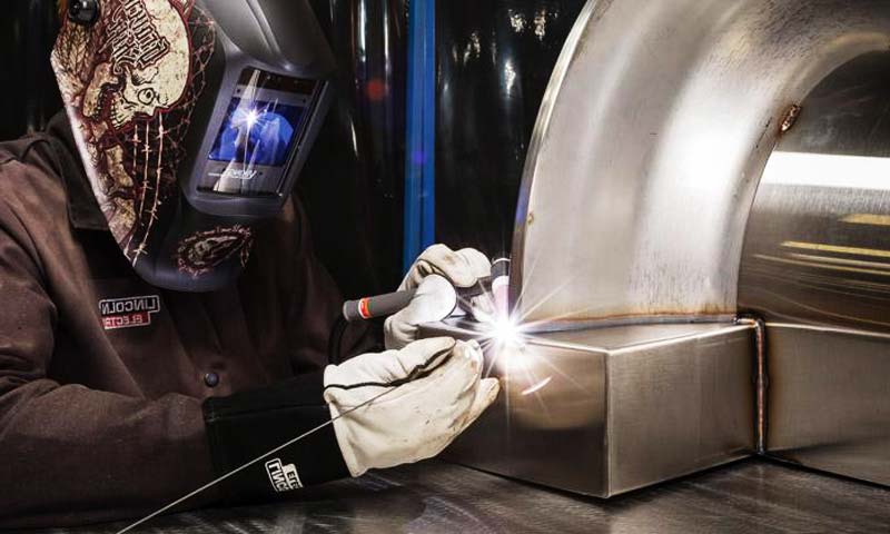
- Joinery Methods: Welding (TIG/MIG for aluminum brackets), adhesive bonding (for lightweight assemblies), or mechanical clamping.
7. Quality, Inspection, and Common Defects for Brackets

Common defects
- Gas porosity: entrapped hydrogen/gases produce spherical porosity.
- Shrinkage porosity: occurs in thick, inadequately fed zones.
- Cold shuts / misruns: from low melt temperature or flow interruptions.
- Hot cracks / hot tears: from tensile strains during solidification in constrained areas.
- Flash and surface blemishes: due to die mismatch or excessive lubricant.
Inspection methods
- Visual + dimensional: first line (CMM, optical measurement).
- X-ray/CT scanning: detect internal porosity and shrinkage (production sampling plan).
- Pressure/leak test: for sealed brackets or those carrying fluids.
- Mechanical testing: tensile, hardness, fatigue samples from production runs.
- Metallography: microstructure, intermetallic phases and porosity quantification.
Controlling defects
- Critical countermeasures: optimized gating/venting, vacuum assist, melt degassing, controlled die temperatures, and appropriate wall/rib geometry.
8. Mechanical Performance of Aluminum Die Casting Brackets
Static behavior
- Design loads should be verified by FEA on as-cast geometry and by testing representative cast parts.
Typical design calculations use the alloy’s measured tensile/yield strength corrected for measured porosity and safety factors appropriate to service (1.5–3× depending on criticality).
Fatigue performance
- Fatigue life is highly sensitive to surface condition, stress concentrations and porosity.
- Fatigue strength of HPDC alloys is typically lower than heat-treated, wrought aluminum due to as-cast porosity.
For dynamic services, specify fatigue testing on production castings or select processes that minimize porosity (vacuum HPDC, squeeze casting).
Example engineering numbers (illustrative)
- For a bracket made of A380 as-cast with UTS ~320 MPa and yield ~160 MPa, design static safety factors commonly range 1.5–2.5 for non-critical parts; higher for safety-critical attachments.
Fatigue verification should include S-N testing to at least 10⁶ cycles where applicable.
9. Corrosion, Thermal, and Electrical Considerations
Corrosion
- Aluminum forms a protective oxide but is vulnerable to pitting in chloride environments and galvanic corrosion when connected to cathodic metals (steel, copper).
Use coatings, sacrificial isolation (washers, sleeves) or select compatible fasteners.
Thermal behavior
- Aluminum’s lower density and higher thermal conductivity compared with steel (thermal conductivity for alloys typically 100–150 W/m·K) make it effective for heat-dissipation brackets.
Be mindful of thermal expansion differences when mating with other materials.
Electrical considerations
- Aluminum is electrically conductive and can serve as a ground or EMI path.
In environments with alternating magnetic fields, eddy currents in large solid brackets may produce heating — design with slots or laminations if needed.
10. Advantages of Aluminum Die Casting Brackets
- Weight reduction: Aluminum density (~2.72–2.80 g/cm³) vs steel (~7.85 g/cm³) yields ≈ 35% of the steel mass for equal volume — i.e., ~65% weight savings for the same geometry, enabling lighter assemblies and fuel/energy savings.
- Complex, integrated geometry: reduces parts count and assembly time.
- Good corrosion resistance: natural oxide plus coatings.
- Thermal and electrical conductivity: useful in thermal management and grounding.
- Recyclability: aluminum scrap is highly recyclable and recycling consumes a small fraction of primary-production energy.
- High volume cost efficiency: HPDC amortized tooling makes unit cost very competitive at scale.
11. Key Applications of Aluminum Brackets
- Automotive & EV: motor mounts, transmission brackets, battery pack supports, sensor/adaptive system mounts.
- Power electronics & e-mobility: inverter/motor mounting structures where heat dissipation and dimensional accuracy are important.
- Telecommunications & infrastructure: antenna mounts, outdoor equipment brackets.
- Industrial machinery: gearbox and pump supports, sensor mounts.
- Appliances & consumer electronics: chassis and internal support brackets with demanding cosmetic/fit requirements.
- Medical & aerospace (selected components): where certification and higher integrity processes (vacuum, LPDC, squeeze) are applied.
12. Aluminum Brackets vs. Steel Brackets
| Category | Aluminum Brackets | Steel Brackets |
| Density / Weight | ~2.7 g/cm³ (lightweight; ~1/3 of steel) | ~7.8 g/cm³ (significantly heavier) |
| Strength-to-Weight Ratio | High; excellent efficiency for weight-sensitive designs | High absolute strength but lower strength-to-weight ratio |
| Corrosion Resistance | Naturally corrosion-resistant; can be enhanced with anodizing or coating | Requires painting, plating, or galvanizing to prevent rust |
| Manufacturing Processes | Very suitable for die casting, extrusion, CNC machining | Commonly stamped, welded, forged, or machined |
| Thermal Conductivity | High (good for heat dissipation applications) | Lower than aluminum |
| Magnetic Properties | Non-magnetic (beneficial for electronics and EMI-sensitive uses) | Magnetic (unless made from stainless steel grades) |
| Fatigue Behavior | Good with proper design; performance depends on porosity control in cast parts | Generally excellent fatigue strength, especially in forged or welded structures |
Cost Level |
Moderate; die casting reduces unit cost in high volumes | Often lower material cost; fabrication can be cheaper for low-volume parts |
| Surface Finishing | Anodizing, powder coating, painting, EN plating | Painting, powder coating, galvanizing, black oxide |
| Stiffness (Elastic Modulus) | Lower (~70 GPa); may require thicker sections for same rigidity | High (~200 GPa); stiffer for the same geometry |
| Weldability | Possible but limited for high-Si die cast alloys; risk of porosity | Excellent for most steels; strong welded joints |
| Recyclability | Highly recyclable with low energy cost | Also recyclable but higher melting energy |
| Typical Applications | Automotive lightweight brackets, electronics housings, aerospace components | Heavy-load supports, industrial frames, structural mounts |
13. Conclusion
Aluminum die-casting brackets are a widely applicable solution when lightweight, high-volume, geometrically complex components are needed.
Success requires a systems approach: choose the right alloy and casting process for the load case and production volume; design with uniform walls, appropriate ribs/bosses and draft;
control melt cleanliness and die temperature; and plan inspection and post-processing (machining, sealing, coatings).
For static, non-fatigue brackets HPDC A380/ADC12 class alloys often suffice; for structural, fatigue-sensitive applications, use vacuum/low-pressure processes, heat-treatable alloys or squeeze casting and validate with fatigue and NDT sampling.
FAQs
What wall thickness should I specify for an HPDC bracket?
Aim for 1.5–4.0 mm for most HPDC brackets. Keep walls uniform and avoid abrupt thickness changes; core out thick zones where possible.
Do die-cast brackets need machining?
Critical mounting faces, bore diameters and threads generally require post-machining. Plan 0.5–1.5 mm machining allowance for datums.
How can porosity be minimized?
Use vacuum-assisted casting, optimized gating/venting, strict melt degassing and controlled die temperatures; consider alternative casting methods for ultra-low porosity.
Are aluminum die-cast brackets suitable for high-fatigue applications?
They can be, but fatigue performance must be demonstrated on production castings.
Prefer vacuum/LPDC or squeeze casting and apply surface enhancement (shot peening, machining) to improve life.
How much lighter is an aluminium bracket compared with a steel bracket of the same volume?
Given typical densities, an aluminum bracket is roughly 35% of the weight of the same-volume steel bracket — i.e., ≈65% lighter, enabling significant system-level mass savings.