Introduction
Casting cracks are one of the most prevalent and destructive defects in metal casting manufacturing.
They severely compromise the structural integrity, dimensional stability, mechanical performance and service safety of cast components, leading to high scrap rates, increased production costs and shortened equipment service life.
In industrial casting production, cracks are scientifically categorized into two exclusive types based on formation stage, microscopic mechanism, morphological features and stress state: hot cracks (hot tears) and cold cracks (cold tears).
Hot cracks occur in the final solidification stage of molten metal, while cold cracks form after complete solidification during the low-temperature elastic cooling phase.
The two defect types differ drastically in macroscopic morphology, microscopic expansion mode, root causes and susceptible alloy systems.
A systematic understanding of their formation mechanisms and targeted resolution strategies is essential for foundry engineers to optimize casting processes, eliminate crack defects and improve the yield rate of high-quality castings.
This article elaborates the full-dimensional characteristics, formation principles, key inducing factors and standardized preventive & remedial solutions for casting hot cracks and cold cracks.
1. Hot Cracks: Formation Mechanism, Characteristics and Solutions
Hot cracks are typical high-temperature casting defects that emerge at the late solidification stage or immediately after solidification, when the casting alloy retains extremely low strength and poor plastic toughness.
They are common in steel castings, malleable iron castings and lightweight alloy castings, and are fundamentally driven by unrelieved shrinkage stress and thermal stress during solidification.
Typical Morphological and Structural Characteristics
Hot cracks possess unique visual and microscopic features that distinguish them from cold cracks:
Macro shape:
Crack lines are tortuous, irregular and uneven in thickness, presenting a wide outer opening and gradually narrowing internal section with a typical tearing, “partially connected” fracture state.
Surface oxidation features:
Crack surfaces form distinct oxide layers without metallic luster.
Steel casting hot cracks appear nearly black, while aluminum alloy cracks show a dull gray tone due to high-temperature oxidation.
Microscopic expansion mode:
Hot cracks germinate and expand along grain boundaries, which is their core microscopic identification feature.
Classification:
Divided into external hot cracks and internal hot cracks.
External cracks are visible on the casting surface, mostly distributed at sharp corners, abrupt wall thickness transitions and stress-concentrated areas with slow local solidification, and may even penetrate the entire casting cross-section in severe cases.
Internal hot cracks form at the final solidification zone inside castings, accompanied by dendritic crystal structures, and rarely extend to the outer surface.
Core Formation Mechanism
After molten metal is poured into the mold, heat dissipates outward through the mold wall, making solidification start from the casting surface and gradually extend inward.
In the late solidification stage, dendritic crystals overlap to form a rigid solid skeleton and begin linear shrinkage.
At this stage, a thin unsolidified liquid metal film still exists between adjacent dendrites.
If the shrinkage of the dendritic skeleton is completely unobstructed, no internal stress will be generated.
However, when the solid shrinkage is restrained by external barriers such as sand molds, sand cores and mold friction, tensile stress accumulates inside the casting.
Once the tensile stress exceeds the ultimate strength of the alloy at high temperatures, intergranular cracking occurs between dendrites.
The occurrence of hot cracks depends on liquid metal replenishment after cracking.
If sufficient molten metal fills the cracked gaps in time, defects will not form; if the cracks cannot be replenished, permanent hot cracks will develop.
Alloys with a wide solidification temperature range and spongy paste-like solidification characteristics are highly susceptible to hot cracking,
while eutectic alloys with constant-temperature solidification have the lowest hot crack tendency.
Key Inducing Factors
The formation of hot cracks is the combined result of structural design, smelting quality and casting process parameters:
- Structural defects: Uneven wall thickness, excessively small inner fillets, excessive branching of overlapping parts, and rigid frame or rib structures that block free solid shrinkage of castings.
- Process irrationalities: Improper size and position of gating and riser systems that restrict shrinkage;
premature mold shakeout leading to rapid and uneven cooling; excessive mold strength with poor deformability. - Material and chemical composition issues: Alloys with high linear shrinkage rates; excessive low-melting impurity elements;
excessive sulfur and phosphorus content in steel and iron castings that deteriorate high-temperature toughness.
Systematic Resolution and Preventive Measures
Optimize Casting Structural Design
Standardize structural design to eliminate inherent stress concentration risks: ensure uniform wall thickness of castings, set rounded transition fillets at all sharp corners to buffer shrinkage stress,
and adopt curved spoke structures for wheel castings to release shrinkage resistance effectively.
Improve Molten Alloy Smelting Quality
Adopt refining and degassing processes to remove oxide inclusions and dissolved gas in molten metal, purify the alloy microstructure.
Strictly control the content of harmful impurities such as sulfur and phosphorus, and avoid excessive low-melting phases to stabilize the high-temperature strength and plasticity of the alloy.
Optimize Casting Process Parameters
Implement the simultaneous solidification principle to balance the cooling rate of all casting parts and minimize thermal stress differences.
Design reasonable gating and riser dimensions and layout to avoid shrinkage obstruction.
Extend the retention time of castings in the sand mold to achieve uniform temperature distribution and reduce internal thermal stress.
Improve the deformability of sand molds and sand cores, remove mold clamping weights and fastening devices in advance,
and partially excavate redundant molding sand for large castings to reduce shrinkage resistance.
Standardize Post-Casting Operation
Avoid collision, extrusion and violent vibration during shakeout, cleaning and handling to prevent secondary tearing of high-temperature castings.
2. Cold Cracks: Formation Mechanism, Characteristics and Solutions
Cold cracks are low-temperature structural defects that form after the casting is completely solidified and cooled to an elastic state.
They occur when local casting tensile stress exceeds the room-temperature ultimate strength of the alloy, and are mainly distributed in stress-concentrated tension zones during the cooling process.
Distinguishing Morphological and Microscopic Features
Cold cracks have completely different characteristics from hot cracks, enabling accurate visual and microscopic identification:
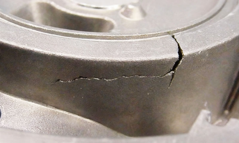
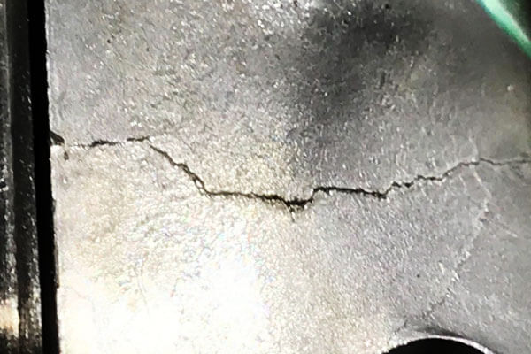
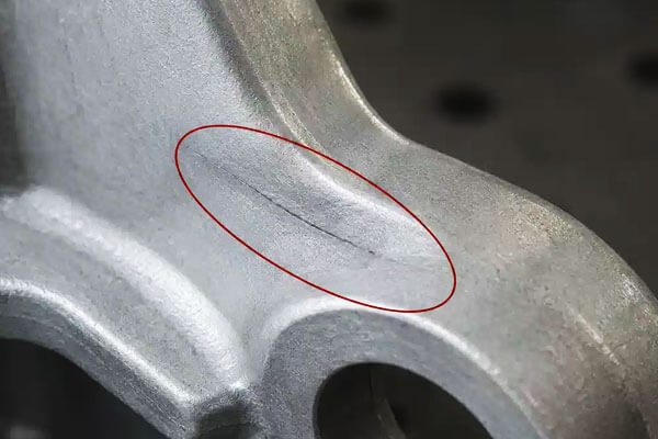
- Macro morphology: Cracks are straight or fold-shaped with uniform, slender and consistent width, featuring smooth and neat fracture lines.
- Fracture state: The fracture surface is clean with obvious metallic luster or slight low-temperature oxidation color, without the rough oxidized layer of hot cracks.
- Microscopic mode: Cold cracks expand in a transgranular manner, penetrating the entire casting cross-section instead of spreading along grain boundaries, which is the most essential difference from hot cracks.
Formation Mechanism
After full solidification, the casting enters the elastic cooling stage.
Uneven cooling speed across different structural parts generates significant temperature gradients, resulting in unbalanced shrinkage deformation.
Restricted by the casting’s own rigid structure and external mold resistance, huge residual tensile stress accumulates inside the component.
When the local tensile stress exceeds the low-temperature yield and tensile strength of the alloy material, transgranular fracture occurs, forming cold cracks.
Main Inducing Factors
Unreasonable Casting Structure
Severely uneven wall thickness causes inconsistent cooling shrinkage; rigid closed structures and thin-wall & large-core structures are prone to constrained shrinkage stress, which easily exceeds the alloy’s tensile strength and triggers cracking.
Defective Gating and Riser System Design
Improper ingate placement (arranged at thick-wall positions) aggravates cooling speed differences and thermal stress concentration.
Undersized or improperly positioned risers block free shrinkage of castings.
Excessively high high-temperature strength and poor deformability of molding sand and core sand further increase shrinkage resistance and tensile stress.
Unqualified Alloy Chemical Composition
Excessively high carbon and alloy element content increases alloy brittleness and reduces low-temperature toughness.
Excessive phosphorus content (over 0.05%) significantly enhances the cold brittleness of steel castings.
Excessive anti-graphitization elements in gray iron castings increase shrinkage volume and induce cold cracks.
Non-Standard Post-Casting Processes
Premature mold shakeout and high-temperature shakeout lead to rapid cooling and sharp stress surge; mechanical collision and extrusion during cleaning and handling directly crack low-toughness castings.
Targeted Resolution and Prevention Strategies
Optimize Structural and Process Design
Optimize wall thickness uniformity, add transition structures for rigid closed parts, and eliminate structural stress concentration.
Redesign the gating and riser system to avoid blocking casting shrinkage and balance the cooling rate of thick and thin sections.
Strictly Control Alloy Composition
Precisely adjust alloy element ratios, strictly limit the content of brittle impurities such as phosphorus, and reduce cold brittleness of the material to improve low-temperature impact toughness.
Standardize Mold Release and Handling Specifications
Properly extend the mold retention time to achieve slow and uniform cooling of castings and release residual stress gradually.
Avoid mechanical impact and extrusion in post-processing procedures.
Implement Stress Relief Heat Treatment
Perform aging heat treatment in a timely manner for castings with large residual casting stress to eliminate internal stress.
Conduct secondary aging treatment after riser cutting and welding repair to prevent delayed cold cracking.
3. The Engineering Principle Behind Crack Prevention
Crack prevention in castings is not a matter of luck or trial and error. It is a matter of engineering balance.
A casting cracks when the metal is forced to withstand tensile stress at a stage when its strength is too low, or when residual stress accumulates faster than the material can relax it.
From this perspective, every crack is the visible result of an invisible mismatch between thermal behavior, solidification behavior, mechanical restraint, and material capability.
The fundamental principle is straightforward: a casting must be allowed to shrink and cool in a controlled, low-resistance manner, while maintaining sufficient feeding and structural support during the vulnerable stages of solidification and cooling.
If any part of that balance is lost, cracking becomes likely.
Crack formation is a stress problem, not just a defect problem
In foundry practice, cracks are often described as hot cracks or cold cracks, but beneath these surface classifications lies the same mechanical truth: the casting experiences stress that exceeds its instantaneous strength.
During solidification, the metal is partially solid and partially liquid. This is the most fragile stage of all.
The dendritic skeleton has formed, but it has not yet developed enough ductility to tolerate large deformation.
If the surrounding mold, core, riser system, or geometry prevents free contraction, tensile stress concentrates in the weak zone. That is the origin of hot cracking.
After solidification, the casting may appear fully sound, but large temperature gradients still exist between the surface and the interior.
As the part cools, the outer layers contract first while the hotter interior resists that contraction. This generates residual stress.
If the stress is not relieved gradually, it can exceed the material’s room-temperature or intermediate-temperature strength and produce cold cracking.
So the real engineering question is not simply “How do we stop cracks?” but rather: How do we design the process so that stress never builds beyond the casting’s temporary strength?
The casting must be designed as a shrinkage system
A casting is not a rigid object during production. It is a body that must change shape slightly and continuously as it cools.
Good design recognizes this and works with thermal contraction instead of against it.
That is why crack-resistant design begins with geometric simplicity and structural uniformity:
- Wall thickness should be as even as possible.
- Sudden changes in section should be avoided.
- Sharp internal corners should be replaced with generous radii.
- Intersections of ribs, bosses, and flanges should be softened rather than abrupt.
- Long rigid frames should be broken up or redesigned to allow contraction.
- Heavy sections should not be isolated from thinner sections without a transition strategy.
When the geometry is stiff and irregular, the casting behaves like a structure with built-in stress concentrators.
The result is not just a higher cracking risk, but also uneven solidification, localized hot spots, feeding difficulty, and residual stress accumulation.
In other words, poor geometry creates a cascade of failures.
A crack-resistant casting design therefore treats shrinkage as a functional requirement, not a nuisance. The part must be allowed to contract predictably.
Solidification must be controlled, not merely accelerated
Many process problems come from misunderstanding cooling rate. Faster is not always better. What matters is not maximum cooling speed, but uniform and coordinated cooling.
If one area solidifies much earlier than another, the early-solidified region becomes a rigid shell while the remaining section is still contracting or feeding.
That imbalance creates tensile stress. If feeding is blocked or the shell is restrained, cracking follows.
For this reason, the designer must understand the solidification pattern of the casting:
- Where are the last-to-freeze regions?
- Where will the thermal center form?
- Which zones will experience the highest restraint?
- Where can liquid metal still feed shrinkage?
- Where will the shell be thin and weak during the final stage?
A robust casting process tries to create a solidification pattern that is deliberate and predictable.
Depending on the alloy and geometry, this may mean directional solidification toward risers, or in some cases near-simultaneous solidification to reduce differential stress.
The key is consistency. Uncontrolled solidification creates stress gradients; controlled solidification manages them.
The mold and core should support shape, not oppose contraction
A mold must hold the casting shape during pouring and initial solidification, but after that it should not behave like a rigid clamp.
If the sand mold or core has excessive strength, poor collapsibility, or insufficient high-temperature yielding behavior, it resists contraction and transforms thermal shrinkage into tensile stress.
This is one of the most overlooked sources of cracking. A mold that is “too good” in the sense of being too rigid can be harmful.
The ideal mold system provides a balanced combination of:
- dimensional stability during pouring,
- adequate erosion resistance,
- sufficient collapsibility after solidification,
- and low restraint during shrinkage.
Core design is especially important in hollow or box-shaped castings.
A core that is too large, too hard, or too strong can become a mechanical brace inside the part.
As the metal contracts around it, stress concentrates in the walls. If the resulting stress exceeds the alloy’s strength, the casting cracks, often in a seemingly unexplained way.
Engineering crack prevention therefore requires not just a metal specification, but a mold behavior specification. The mold is part of the mechanical system.
Feeding and restraint must be balanced together
Risers are often discussed only in terms of shrinkage compensation, but their function is more subtle.
A riser must feed metal to shrinkage zones, but if the gating and risering layout creates local restraint, it may also become part of the cracking problem.
A good feeding system should:
- supply liquid metal to the last-solidifying areas,
- avoid trapping isolated hot spots,
- prevent premature gating freeze-off,
- and not lock the casting into a rigid stress field.
If a gate freezes too early, it can block the natural contraction of the casting.
If a riser or feeder is positioned so that it mechanically restrains shrinkage, the casting may tear near the connection region.
This is especially common where there is a large stiffness mismatch between the casting body and the attached feeding system.
The principle here is critical: feeding metal and releasing shrinkage stress are both necessary, but they are not the same thing.
A process that feeds well but restrains contraction may still crack. The design must accomplish both functions at once.
Residual stress must be reduced before it becomes a crack
Not all cracks appear immediately. Some castings exit the mold intact and crack later during shakeout, cleaning, machining, or handling.
That means the casting contained residual stress that had not yet been fully released.
Residual stress is unavoidable to some degree, but its magnitude can be controlled. The main engineering tools are:
- uniform section design,
- proper mold collapsibility,
- controlled cooling in the mold,
- appropriate shakeout timing,
- stress-relief heat treatment,
- and careful handling after solidification.
The purpose of stress-relief heat treatment is not to change the shape of the part, but to lower internal stress to a safer level.
For high-stress castings, this is often the difference between a stable part and a delayed crack.
In large or complex castings, stress relief is especially important because the temperature gradients and section variation are usually greater.
In such cases, the casting may appear dimensionally stable while still carrying dangerous internal stress.
Once machining removes a support surface or opens a locked-in stress path, the crack can appear suddenly.
Material selection must match the geometry and process
A crack-resistant process is only possible when the alloy’s behavior is compatible with the part design and foundry process.
Some alloys have wider solidification ranges, lower hot ductility, or greater contraction sensitivity.
These alloys may be perfectly suitable in one geometry and highly crack-prone in another.
That means alloy selection cannot be separated from design. The engineer must consider:
- solidification range,
- hot tearing sensitivity,
- linear shrinkage,
- ductility during the semi-solid stage,
- toughness after solidification,
- susceptibility to embrittling elements,
- and the effect of impurities such as sulfur or phosphorus.
A geometry with sharp transitions and strong restraint demands a more crack-tolerant alloy than a simple, uniformly sectioned part.
Likewise, an alloy with known hot cracking sensitivity may require modified gating, lower restraint, improved mold collapsibility, or slower controlled cooling.
In practice, many crack problems are not solved by process tuning alone. Sometimes the material must change, or the design must be relaxed to fit the alloy’s real behavior.
Handling after solidification is part of the crack-prevention system
Crack prevention does not end when the metal freezes. A casting can still fail during shakeout, cutting, grinding, shot blasting, or transportation.
Once the part has solidified, it may still be fragile because of high residual stress, low temperature toughness, or hidden microcracks.
For that reason, post-solidification operations should be treated as part of the metallurgical process:
- shakeout should not be too early,
- parts should not be dropped or struck,
- gate removal should be controlled,
- machining should avoid abrupt force application,
- and storage should prevent stacking loads or bending stress.
This is particularly important for large thin-walled castings and rigid castings with long spans. These parts may look robust but can be surprisingly sensitive to local impact or bending.
4. Core Differences Between Hot Cracks and Cold Cracks
| Item | Hot Cracks | Cold Cracks |
| Formation stage | Occur during the final stage of solidification or shortly after solidification, when the casting is still at a very high temperature | Occur after solidification, during cooling into the elastic range or after the casting has cooled further |
| Root cause | Tensile stress generated by restrained solidification shrinkage in a weak semi-solid structure | Residual thermal stress or external restraint exceeding the alloy’s strength during cooling |
| Material state at cracking | Semi-solid or near-solid, with very low strength and ductility | Fully solid, but still under significant internal stress |
| Typical crack path | Usually intergranular, propagating along grain boundaries | Usually transgranular, propagating across grains and through the section |
| Crack shape | Irregular, curved, tortuous, and often branched | Straight or slightly zigzag, with relatively uniform width |
Surface appearance |
Rough fracture surface, often oxidized, dull, and lacking metallic luster | Cleaner fracture surface, often metallic bright or only lightly oxidized |
| Crack opening | Often wider at the surface and narrower inside | Usually more uniform in width along the crack line |
| Common locations | Hot spots, sharp corners, thick-to-thin transitions, restrained regions, last-to-solidify zones | Highly stressed regions, restrained sections, corners, core-restrained areas, near gates or stiff structural zones |
| Influencing factors | Wide solidification range, poor feeding, high shrinkage tendency, strong mold restraint, poor collapsibility | Uneven cooling, high residual stress, rigid structure, poor mold/core yield, brittle alloy chemistry |
| Typical alloys prone to it | Steels, malleable cast irons, and some light alloys | Brittle or low-toughness alloys, steels with high carbon or phosphorus, cast irons with unfavorable chemistry |
Detection method |
Often visible on the surface; internal hot cracks may require sectioning or NDT | Often visible after cooling; internal cracking may also require sectioning or NDT |
| Prevention focus | Improve solidification feeding, reduce restraint, refine geometry, increase mold collapsibility, avoid hot spots | Reduce residual stress, improve cooling uniformity, optimize shakeout timing, improve heat treatment, strengthen toughness |
| Key engineering principle | Prevent the semi-solid skeleton from tearing under shrinkage stress | Prevent cooled metal from cracking under accumulated residual stress |
| Typical corrective action | Redesign geometry, adjust risering/gating, modify mold conditions, improve alloy quality | Stress relief, slower and more uniform cooling, better core/mold collapsibility, chemistry control, careful handling |
5. Conclusion
Cracks in castings form because the metal is asked to shrink, solidify, and cool under restraint. When that restraint creates stress greater than the alloy can tolerate, the casting tears apart.
Hot cracks appear during solidification, usually with irregular, oxidized, intergranular features.
Cold cracks appear during later cooling, usually as straighter, cleaner, through-thickness fractures driven by residual stress.
The remedy is equally systematic: improve casting design, reduce stress concentration, optimize solidification, choose suitable alloy chemistry, improve mold collapsibility, control shakeout time, and apply stress-relief heat treatment when needed.
In practice, the best crack-free casting is not the one that is “strongest” in the mold, but the one that is allowed to shrink in a controlled, balanced, and predictable way.