1. Executive summary
Aluminum die-cast enclosures deliver an unmatched combination of mechanical strength, dimensional accuracy, thermal conductivity and electromagnetic shielding in a single near-net form.
For many electronic and electromechanical products where thermal dissipation, EMI shielding and mechanical robustness are priorities,
Aluminum HPDC enclosures are the preferred solution versus sheet metal or plastic housings-provided the enclosure is designed with die-casting constraints (wall thickness, draft, ribs, bosses) and appropriate downstream machining and sealing.
The main tradeoffs are tooling cost and per-part finish/processing steps; for medium to high volumes, HPDC is highly economical.
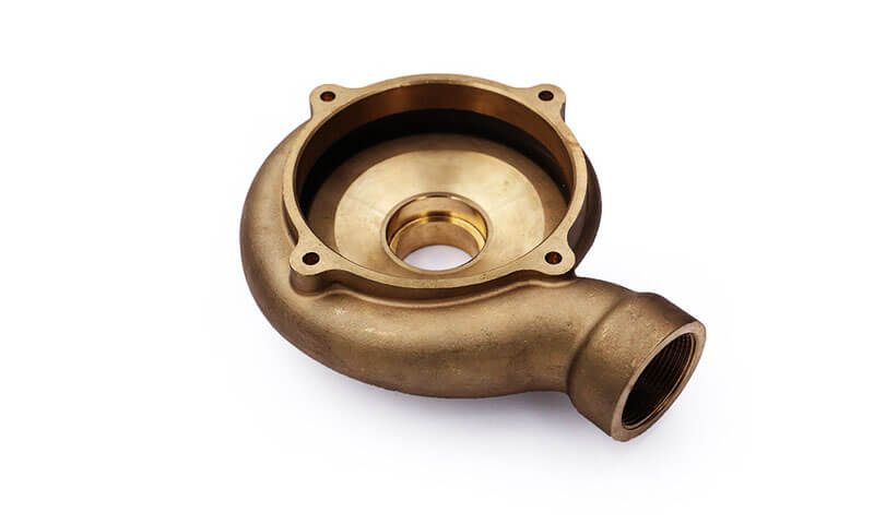
2. What is an aluminum die-cast enclosure?
An aluminum die-cast enclosure is a housing produced primarily by high-pressure die casting (HPDC) using an aluminum alloy (e.g., A380/ADC12 family, A356 variants or specialized die-casting alloys) and then finished with machining, surface treatment and sealing.
Typical features integrated into the cast part include mounting bosses, standoffs, ribs, cable entry ports, bosses for threaded inserts, heat-sink fins, and flanges for gaskets or connectors.
Die-casting produces a near-net shape with fine surface detail and repeatable dimensional tolerances.
Why choose die-cast aluminum for enclosures?
- High stiffness and impact resistance (protects electronics)
- Excellent thermal conduction for passive heat dissipation
- Inherent EMI/RFI shielding (electrically conductive continuous metal)
- Ability to integrate structural and thermal features in one part
- Good surface quality for coatings and aesthetic finishes
- Recyclable and widely available
3. Materials & Alloy choices
Aluminum alloys used for die cast enclosures are chosen based on castability, mechanical strength, thermal conductivity, corrosion resistance and machinability.
Below is a compact table of common choices and their typical performance envelopes (engineering guidance — verify supplier datasheets for exact values).
| Alloy / Common name | Typical use in enclosures | Density (g/cm³) | Typical tensile strength (MPa) | Typical thermal conductivity (W·m⁻¹·K⁻¹) | Notes |
| A380 / AlSi9Cu3(Fe) (die-casting standard) | General-purpose die-cast enclosures | ~2.68–2.80 | ~150–260 (as-cast) | ~100–140 (alloy-dependent) | Best for high-volume HPDC; good castability and detail; moderate strength |
| ADC12 (similar to A380) | Automotive & electronic housings | ~2.7 | ~160–260 | ~100–140 | Widely used in Asia; good thin-wall capability |
| A356 / AlSi7Mg (gravity/PM & sometimes HPDC) | Higher-strength, heat-treatable enclosures & heat-sinks | ~2.65–2.70 | ~200–320 (T6) | ~120–160 | Heat treatable (T6) gives better mechanical & fatigue properties; often used when higher thermal performance and pressure resistance required |
| A413 / AlSi12Cu (castings) | Specialized housings, thermally demanding parts | ~2.7 | ~200–300 | ~110–150 | Balance of strength and conductivity |
Notes: values are typical ranges for design estimation. Die-cast alloys have lower ductility than wrought aluminum and show porosity differences depending on process.
Thermal conductivity of cast aluminum alloys is lower than pure aluminum (237 W/m·K) but still favorable for thermal management compared with plastics.
4. Die-casting processes & variants relevant to aluminum enclosures
Aluminum die-cast enclosures can be produced by several casting technologies.
Each process offers a different balance of geometry capability, surface quality, porosity (integrity), mechanical properties, cost and throughput.
Summary table — processes at a glance
| Process | Typical production scale | Typical min wall (mm) | Relative porosity / integrity | Surface finish (Ra) | Key strengths | When to choose |
| High-Pressure Die Casting (HPDC) | High → very high | 1.0–1.5 | Moderate (can be improved) | 1.6–6 µm | Extremely high throughput, thin walls, fine detail, excellent dimensional repeatability | High-volume enclosures with thin walls and many integrated features |
| Vacuum HPDC | High (premium) | 1.0–1.5 | Low porosity (best HPDC variant) | 1.6–6 µm | All HPDC benefits + reduced gas porosity and improved mechanical/fatigue behaviour | Enclosures needing higher integrity, pressure seals, or improved fatigue life |
| Low-Pressure Die Casting / Gravity Low-Pressure (LPDC) | Medium | 2–4 | Low (good) | 3–8 µm | Good integrity, lower turbulence, better mechanical properties than HPDC | Medium volumes where integrity and mechanical properties matter |
| Squeeze Casting / Rheo / Semisolid | Low → medium | 1.5–3 | Very low porosity | 1.6–6 µm | Near-forged properties, low porosity, excellent mechanicals | Enclosures requiring higher strength/fatigue resistance; smaller volumes |
Permanent-mold / Gravity (PM) |
Low → medium | 3–6 | Low | 3–8 µm | Good mechanical properties, low porosity, longer die life than sand | Medium-volume, thicker-walled enclosures and structural parts |
| Investment Casting | Low → medium | 0.5–2 | Low (good) | 0.6–3 µm | Excellent detail and surface finish, thin sections possible | Small, precision enclosures or parts with complex internal geometry |
| Sand Casting (resin / green) | Low | 6+ | Higher (larger sections) | 6–25 µm | Low tooling cost, flexible sizes | Prototypes, very low volumes, very large enclosures |
| Lost-foam / Additive (hybrid) | Low | 1–6 (geometry dependent) | Variable | Variable | Quick tooling for complex forms, fewer cores | Rapid prototypes, design validation, low-volume customized enclosures |
Detailed process descriptions & practical implications
High-Pressure Die Casting (HPDC)
- How it works: Molten aluminum is injected at high speed/pressure into a steel die (two halves), rapidly solidified and ejected. Typical cycle times are short (seconds to a few minutes).
- Typical process parameters: molten temperature ~680–740 °C (alloy dependent); die temperature ~150–220 °C; fast shot velocities and high intensification pressures compress metal into thin features.
- Performance: excellent dimensional accuracy, fine detail (logos, ribs, thin fins) and low unit cost at scale.
- Tradeoffs: HPDC tends to trap gas/turbulence-born porosity and may produce a slightly less ductile microstructure than gravity methods. Vacuum HPDC and optimized gating/venting strongly reduce these issues.
- Practical tip: specify vacuum HPDC if sealing faces, tapped bosses or fatigue life are critical; otherwise conventional HPDC is lowest cost for simple enclosures.
Vacuum HPDC (vacuum assist)
- Benefit: pulls air out of cavity and runner system during filling — reduces entrapped air and hydrogen-related porosity, improves mechanical properties and leak tightness.
- Use case: IP-rated enclosures with machined sealing faces, connectors under pressure or enclosures in vibration-critical applications.
Low-Pressure Die Casting / Gravity Low-Pressure (LPDC)
- How it works: molten metal is forced into a closed die by low positive pressure from below (or filled by gravity), producing gentle filling and low turbulence.
- Performance: better soundness and less porosity than HPDC; better microstructure and fatigue life.
- Use case: moderate volumes where mechanical integrity matters but HPDC economics are not required.
Squeeze Casting / Semisolid (Rheo / Thixo)
- How it works: semisolid slurry or metal is solidified under pressure in a closed die. Results are near-full density and fine microstructure.
- Performance: properties close to forging (high strength, low porosity), better surface finish than conventional casting.
- Use case: enclosures requiring high mechanical/fatigue performance but in modest volumes.
Permanent Mold / Gravity Die
- How it works: reusable metal molds are filled by gravity; slower than HPDC but gentler filling.
- Performance: lower porosity, better mechanicals than HPDC; limited complexity vs HPDC.
- Use case: medium volumes demanding higher integrity (e.g., housings with larger wall sections).
Investment Casting (Lost-wax, silica-sol)
- How it works: pattern (wax/3D printed) coated with ceramic shell, dewaxed and ceramic shell fired, then filled with molten metal (usually in vacuum/inert for reactive alloys).
- Performance: excellent surface finish and thin wall capability; complex internal features; slower throughput and higher cost.
- Use case: small precision housings, internal complex channels, or when best cosmetic finish/feature fidelity is required.
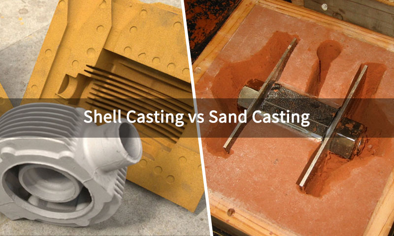
Sand Casting (Green/Resin)
- How it works: expendable sand molds formed around patterns; flexible but coarse surface and dimensional variation.
- Performance: high porosity risk in thin sections and coarser finish; low tooling cost.
- Use case: prototypes, very low volumes, very large enclosures or when tooling investment is prohibitive.
Lost-foam / Additive hybrid
- How it works: foam patterns or 3D-printed patterns are coated or embedded in sand; metal vaporizes pattern on pour; hybrid additive-to-casting workflows are increasing for rapid NPI.
- Performance & use: good for complex shapes and low-volume customization; variable integrity depending on process control.
How process choice affects enclosure attributes
- Wall thickness & features: HPDC excels at thin external walls and integrated bosses; PM and investment better for thicker, stress-bearing bosses.
- Porosity & leak tightness: Vacuum HPDC, LPDC, squeeze casting and permanent mold give lowest porosity; HPDC without vacuum can require sealing or design allowances for critical faces.
- Mechanical & fatigue strength: squeeze/semisolid and permanent-mold parts generally outperform standard HPDC in fatigue-critical applications.
HIP (post-cast Hot Isostatic Pressing) is an option to close internal porosity for very high-reliability parts (but costly). - Surface finish & detail: investment casting > HPDC > permanent mold > sand casting. Fine logos, texturing and visible cosmetics are easiest with HPDC and investment casting.
- Tooling & unit economics: HPDC tooling cost is highest but unit cost lowest at high volumes.
Sand and investment offer low tooling cost but higher per-part price at volume. Permanent mold tooling falls between.
5. Mechanical, Thermal, and Electrical performance
Density: ~2.68–2.80 g/cm³ — about 1/3 of steel, reducing product weight.
Stiffness / modulus: ~68–72 GPa (aluminum class) — lower than steel, but sufficient when designed with ribs and wall thickness.
Typical tensile strength (die-cast): ~150–260 MPa (HPDC alloys); up to ~300 MPa for heat-treated A356 T6.
Thermal conductivity: typical cast alloys ~100–160 W/m·K (alloy and porosity dependent). This is far superior to plastics and aids passive cooling.
Electrical conductivity & EMI shielding: continuous aluminum shell is an effective conductive barrier; good for baseline shielding, especially when gaskets and conductive interfaces are controlled.
Implications:
- Aluminum enclosures provide structural protection and heat-spreading for power electronics.
- For mechanical robustness, use ribs and flanges — die-casting easily integrates them.
- For EMI performance, continuous conductive surfaces and good contact at seams (with conductive gaskets or overlapping flanges) are essential.
6. Design for die cast — geometry, features, and DFM rules
Good die-casting design is decisive. Below is a practical design guideline table and key rules that designers should follow.
Key DFM rules (summary)
- Wall thickness: aim for uniform walls. Typical HPDC minimum: 1.0–1.5 mm for simple shapes; practical enclosure exterior walls often 1.5–3.0 mm. Avoid thick islands—use ribs rather than local thickness increases.
- Draft angle: provide 1–3° draft on all vertical faces (more for deep features).
- Ribs: use ribs to stiffen — rib thickness ≈ 0.5–0.8× nominal wall thickness; avoid ribs that create closed sections.
- Bosses / standoffs: boss outer wall ≈ 1.5–2.0× main wall thickness; include radius between boss and wall; include drain/gage holes for venting; incorporate proper root thickness to avoid shrinkage.
- Fillets & radii: use generous fillets at transitions (≥1–2× wall thickness) to reduce stress concentration and feeding issues.
- Undercuts: minimize undercuts; where needed use slides or split dies which increase tooling cost.
- Sealing faces: cast slightly oversized and machine to flatness; specify surface finish (Ra) for gasket sealing.
- Threading: avoid molded threads for repeated assembly — prefer machined threads or heat-set/insert threads (see Section 10).
- Vent & gating: locate gates and vents to minimize porosity in sealing faces and bosses; coordinate with foundry for gating plan.
Compact DFM table
| Feature | Typical guideline |
| Min wall thickness (HPDC) | 1.0–1.5 mm; prefer ≥1.5 mm for rigidity |
| Typical wall thickness (enclosure) | 1.5–3.0 mm |
| Draft angle | 1–3° (external) |
| Boss diameter:min wall ratio | Boss OD 3–5× wall thickness; boss thickness 1.5–2× wall |
| Rib thickness | 0.5–0.8× wall thickness |
| Fillet radius | ≥1–2× wall thickness |
| Machined sealing face allowance | 0.8–2.0 mm extra stock |
| Thread engagement | 2.5× screw diameter in aluminum (or use insert) |
These are rules-of-thumb — consult the die-caster early for optimization and simulation.
7. Sealing, Ingress protection, and Gasketing strategies
Electronic enclosures often must meet IP ratings. Key considerations:
- Gasket groove design: use rectangular or dovetail grooves sized for gasket compression (e.g., 20–30% compression). Provide continuous groove geometry and avoid dead spaces.
- Face flatness & finish: machine sealing faces to flatness and specify Ra (e.g., Ra ≤ 1.6 µm) for good elastomer adhesion.
- Fasteners & compression sequence: specify bolt torque, spacing, and use of captive screws or threaded inserts to prevent gasket extrusion. Consider multiple smaller screws for uniform compression.
- Gasket materials: choose silicone, EPDM, neoprene or specialized fluorosilicons based on temperature/chemical exposure and hardness (shore A 40–60 typical). For EMI shielding use conductive elastomer gaskets.
- Drainage & venting: provide weep holes or vent membranes for pressure equalization; use breathable vents to prevent condensation while maintaining IP.
- Sealed connectors & cable glands: use certified cable glands for IP67/68 applications. Consider potting or molded overmolds for harsh environments.
Qualification: for IP67/68 specify immersion and dust tests per IEC 60529 and detail test conditions (depth, duration, temperature).
8. Thermal management and heat-dissipation strategies
Aluminum die-cast enclosures are frequently used as structural heat sinks.
Design strategies:
- Direct mounting of heat-producing components to the enclosure base or dedicated boss area to conduct heat into the body.
Use thermal interface materials (TIMs), thermal pads, or thermally conductive adhesives for improved contact. - Integrate fins and increased surface area on external surfaces; HPDC can form complex fin geometries if die design allows.
Fins should be thick enough to avoid breakage yet thin enough for convective cooling. Typical fin thickness 1–3 mm with spacing optimized for airflow. - Use internal conduction paths: internal ribs and thickened pads that route heat to outer shell.
- Surface finish for heat transfer: matte or anodized surfaces can change emissivity; anodizing reduces thermal contact conductivity where coating is present — account for that when designing conduction cooling.
- Forced convection: design intake/outlet openings (with filtration for dust) and provide mounting features for fans or blowers. For IP rated enclosures, consider conduction cooling or heat pipes to avoid vents.
- Thermal modeling: use CFD to balance conduction, convection and radiation; thermal simulations should consider PCB layout, power loss maps and worst-case ambient.
Rule of thumb: aluminum enclosure conduction paths typically reduce PCB hotspot temperatures significantly versus plastic enclosures; quantify with thermal resistance (°C/W) for the intended assembly.
9. EMI / RFI shielding and grounding considerations
Aluminum enclosures provide a conductive barrier but require careful design for high shielding effectiveness:
- Seam control: ensure seam contact surface area is sufficient and apply conductive gaskets at joints if needed. Overlapping flanges with conductive fastener compressions are effective.
- Surface finish & plating: chromate conversion, nickel plating or conductive paints can improve corrosion resistance and maintain conductivity.
Non-conductive coatings (some paints) reduce shielding unless contact points are left uncoated or conductive paths are provided. - Gasket selection: conductive elastomer gaskets (silicone with silver or nickel impregnations) provide EMI sealing at seams and around access panels.
- Cable & connector feed-throughs: use filtered feed-throughs or shielded connectors; maintain 360° shielding continuity.
- Grounding strategy: designate one or more ground points with star grounding to avoid ground loops; use captive studs or welded lugs for external ground points.
- Testing: measure shielding effectiveness (SE) per IEEE 299 or MIL-STD-285; typical well-designed aluminum enclosures can provide 60–80 dB SE over relevant frequency bands with proper gasketing.
10. Machining, Inserts, and Assembly methods
Post-cast machining usually required for mating faces, thread holes, connector mounting areas and precision features.
- Machining allowances: specify machining stock on cast parts (0.8–2.0 mm depending on process) on critical surfaces.
- Threading: use helicoil or steel inserts (e.g., PEM, clinch nuts or threaded bushings) where repeated assembly is expected.
For thin wall bosses use self-tapping screws with controlled torque or insert nuts. - Thread engagement: aim for ≥2.5× screw diameter engagement in aluminum or use steel insert.
- Press-fit & snap-fit: possible for internal retention, but consider thermal cycles and creep in aluminum.
- Fastener torques: specify maximum torque to avoid boss stripping. Use torque-limiting tools in assembly.
- Surface mounting features: boss reinforcement and gussets to support connectors and frequent handling.
Quality controls: runout, flatness and thread gauges; CMM inspection for critical geometries; maintain datums during machining.
11. Surface finishes, coatings and corrosion protection
Common finishes for die-cast enclosures:
- Chromate conversion (Alodine/Chem Film): improves corrosion resistance and paint adhesion; note environmental regulations favor non-hexavalent processes.
- Anodizing: decorative and corrosion protective; thick anodize increases dielectric isolation and may reduce thermal conduction at interface—plan mounting pads uncoated or with removed coating for thermal contact.
- Powder coating / paint: good aesthetics and corrosion protection; must manage seam conductivity for EMI (use conductive gaskets or masked contact surfaces).
- Electroless nickel / nickel plating: improves wear and corrosion resistance; maintains electrical conductivity.
- Mechanical finishing: bead blasting, tumbling, polishing for cosmetic finish.
Selection notes: for EMI-critical designs leave seal faces uncoated or provide conductive paint/plating at the flange/gasket area. For outdoor use select corrosion-resistant coatings and proper sealing.
12. Testing, Qualification, and Standards
Key tests and standards commonly applied:
- Ingress Protection (IP) testing: IEC 60529 (IPxx ratings for dust and water). Typical targets: IP54, IP65, IP66, IP67 depending on environment.
- Salt spray / corrosion: ASTM B117 for coatings; real service conditions may require immersion or cyclic corrosion testing.
- Thermal cycling & shock: validate thermal fatigue and dimensional stability (e.g., per MIL-STD-810).
- Vibration & shock: IEC 60068-2, automotive or MIL standards depending on application.
- EMC / EMI testing: per FCC, CE EMC Directive, MIL-STD-461 (military), IEEE 299 for shielding effectiveness.
- Mechanical testing: drop, impact and torque tests for connectors.
- Pressure / leak test: if housing is pressurized or potted, test for leaks and seal integrity.
- RoHS / REACH compliance: material selection and coatings must meet regulatory requirements in targeted markets.
13. Manufacturing economics, Lead time, and Volume considerations
- Tooling cost: die cost is high (tens to hundreds of kUSD depending on complexity and cavities) — justified for medium to high volumes.
- Unit cost: HPDC yields low per-part cost at scale; for low volumes prototype options include 3D printed patterns, sand casting or CNC machined aluminum.
- Cycle time: HPDC cycles are short (seconds to minutes), enabling high throughput.
- Post-processing cost: machining, heat treatment, surface finishing, insert installation and assembly add to per-part cost; design to minimize expensive secondary operations.
- Break-even: typically die casting becomes economical when annual volumes exceed thousands of parts, but this varies widely.
Supply chain tips: early engagement with die-caster reduces iteration, and modularizing parts (inner frames vs outer covers) may reduce tooling complexity.
14. Environmental, health & safety and recyclability
- Recyclability: aluminum is highly recyclable with low energy cost to re-melt vs primary production. Die-cast scrap and end-of-life housings have high scrap value.
- Coating environmental compliance: prefer non-hexavalent conversion coatings and compliant paint chemistries for ROHS/REACH.
- Foundry H&S: control of molten metal, dust, and smoke during finishing and coating; proper ventilation and PPE required.
- Life-cycle benefits: lightweight housing reduces shipping and may decrease energy consumption in mobile applications.
15. Typical industry applications & case examples
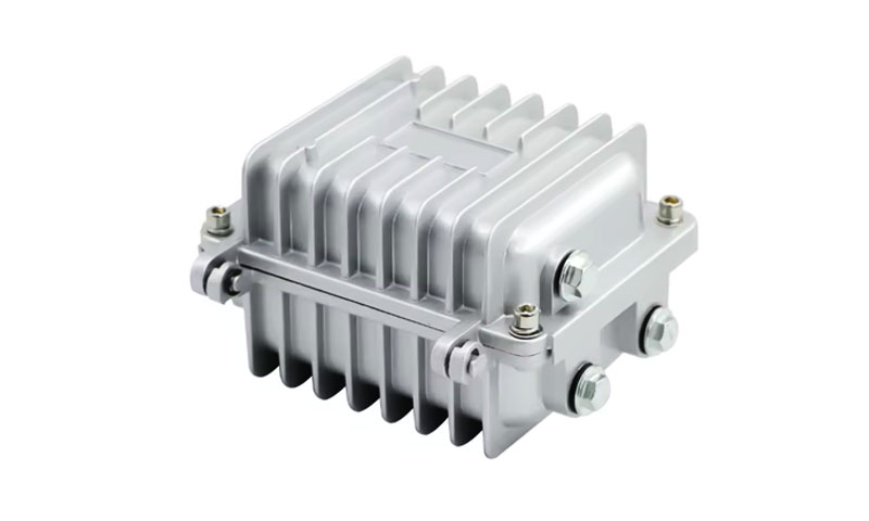
- Power electronics / inverters (solar, EV, motor drives): enclosures conduct and dissipate heat; must meet EMI and environmental protection.
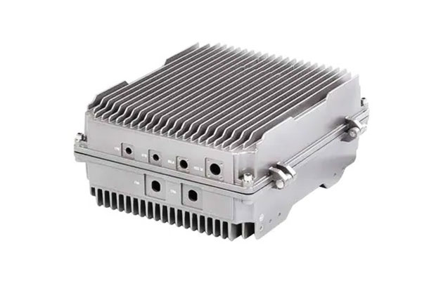
- Telecommunications base stations & radio heads: EMI shielding and weather resistance.
- Automotive ECUs & power modules: combined structural and thermal role; vibration and temperature cycling critical.
- Industrial controls & instrumentation: enclosure protects controllers in harsh environments (IP66 versions common).
- Medical devices & imaging electronics (non-implant): require hygienic finishes and EMI control.
- Outdoor IoT / smart city nodes: small die-cast housings with integrated flanges and antenna mounts.
16. Aluminum Die-Cast Enclosures vs. Alternatives — Comparison Table
Below is a compact, engineering-oriented comparison of aluminum die-cast enclosures (HPDC) versus common alternative materials/processes.
| Material / Process | Density (g·cm⁻³) | Thermal conductivity (W·m⁻¹·K⁻¹) | Typical tensile strength (MPa) | EMI shielding | Typical surface finish | Relative cost (unit, mid-volume) | Best use cases |
| Aluminum HPDC (A380 / ADC12) | ~2.7 | ~100 – 140 | ~150 – 260 | Very good (continuous metal shell) | Smooth as-cast → paint / powder / anodize | Medium | High-volume electronic enclosures requiring thin walls, integrated bosses, basic thermal dissipation and EMI shielding |
| Aluminum (A356 T6, gravity / vacuum HPDC) | ~2.65 | ~120 – 160 | ~200 – 320 (T6) | Very good | Good → can be machined & anodized | Medium–High | Enclosures needing higher mechanical integrity, improved fatigue/thermal performance or pressure seals |
| Sheet-metal Steel (stamped / folded) | ~7.85 | ~45 – 60 | ~300 – 600 (grade dependent) | Very good (with continuous seams & gaskets) | Painted / powder coated | Low–Medium | Low-cost enclosures, large panels, simple shapes; where weight is less critical and toughness is required |
| Stainless Steel (sheet) | ~7.7–8.1 | ~15 – 25 | ~450 – 700 | Excellent (conductive, corrosion resistant) | Brushed / electropolished | High | Corrosive or hygienic environments, high strength & corrosion resistance required |
Plastic Injection Molded (PC, ABS, PPO) |
~1.1–1.4 | ~0.2 – 0.3 | ~40 – 100 | Poor (unless metallized) | Smooth, textured | Low | Low-cost, dielectric enclosures, indoor consumer electronics, non-EMI critical applications |
| Die-cast Zinc (Zamak) | ~6.6–7.1 | ~100 – 120 | ~200 – 350 | Good | Very fine surface detail; easy plating | Medium | Small, detailed housings where weight is less critical and high detail is needed; decorative finishes |
| Die-cast Magnesium | ~1.8 | ~70 – 90 | ~200 – 350 | Very good | Good as-cast; can be machined/painted | Medium–High | Ultra-lightweight enclosures with good thermal conduction (automotive, aerospace electronics) |
| Extruded / Fabricated Aluminum (sheet/extrusion + machining) | ~2.7 | ~205 (pure Al), alloys lower | 200 – 400 (alloy dependent) | Very good | Excellent (anodize, machined finish) | Medium–High | Precision enclosures, heat-sink integrated parts, low- to mid-volume runs where NPI & tooling costs must be limited |
| Metal Additive Manufacturing (AlSi10Mg / 316L) | 2.7 / 8.0 | 100 (Al) / 10–16 (316) | 250–500 (material dependent) | Very good | As-built → machined & finish | High | Low-volume, complex internal channels, rapid iteration prototypes, highly optimized thermal paths |
Notes & selection guidance
- Weight: aluminum (≈2.7 g·cm⁻³) gives the best weight-to-stiffness trade vs steels or zinc; magnesium is lighter still but cost/process limited.
- Thermal management: aluminum alloys offer substantially better thermal conduction than plastics and stainless steels — a major reason to choose die-cast aluminum for power electronics.
- EMI performance: metal housings (aluminum, steel, zinc, magnesium) provide inherently good EMI shielding; plastics require metallization or conductive gaskets to match.
- Structural integrity & porosity: HPDC parts may exhibit porosity — use vacuum HPDC, LPDC, or A356 (T6) routes where leak tightness, fatigue life or machined sealing faces are critical.
- Surface finish & corrosion: die-cast aluminum accepts a wide range of finishes (powder coat, paint, electroless nickel, chromate conversion, anodize). Stainless offers superior bare-metal corrosion resistance.
- Economics: HPDC has high tooling cost but low unit cost at volume. Sheet-metal is cheaper tooling-wise for low volumes but less capable of complex integrated features. AM is expensive per part but enables unparalleled geometry freedom.
17. Conclusion
Aluminum die-cast enclosures provide engineers a powerful platform that integrates mechanical protection, heat conduction and EMI shielding in a single manufacturable package.
Successful use demands early focus on DFM for die casting, correct alloy and process selection (vacuum HPDC or A356 T6 when integrity and thermal performance are critical), clear sealing and EMI strategies, and well-specified finishing and testing.
When designed and specified correctly, die-cast aluminum enclosures can reduce assembly complexity, improve reliability and provide a premium, durable housing for modern electronics.
FAQs
When should I prefer die-cast aluminum over sheet-metal enclosures?
Prefer die-cast aluminum when you need integrated ribs/bosses, superior thermal conduction, higher mechanical robustness, and EMI shielding. Sheet metal excels for very low tooling cost, thin profile and simple shapes.
Can I use painted die-cast enclosures and still meet EMI requirements?
Yes — but ensure gasketed conductive contact at seams, or provide uncoated conductive contact pads. Conductive paints or plating on flange areas also help.
Are molded/aluminum enclosures waterproof?
They can be—when sealing faces are machined to flatness, appropriate gaskets and cable glands are used, and the design is tested and qualified to the intended IP rating.
How do I prevent gasket creep and compression set over time?
Specify durable gasket materials, design for appropriate compression (20–30%), maintain bolt pattern and torque, and select inserts if fasteners are frequently cycled.
What is the typical lead time for production tooling?
Tooling lead time varies with complexity—typically 6–20 weeks. Early supplier involvement and design for manufacturability reduce iteration and time to production.
How do aluminum die-cast enclosures achieve EMI shielding?
EMI shielding is achieved via: 1) Aluminum’s inherent conductivity (50 dB baseline); 2) Integrated internal shielding ribs (add 40–60 dB); 3) Conductive surface treatments (electroless nickel, conductive paint, adding 15–30 dB).
What is the maximum IP rating for aluminum die-cast enclosures?
Aluminum die-cast enclosures can achieve IP68 (submersion beyond 1 m) with vacuum die casting (porosity <1%) and precision sealing groove design (±0.1 mm tolerance) paired with Viton O-rings.
Can aluminum die-cast enclosures be used in high-temperature applications?
Yes—standard enclosures (A380/ADC12) operate up to 125°C; high-temperature alloys (6061) with hard anodizing can handle 150–200°C (suitable for engine-mounted electronics).