1. Introduction
Cast aluminum tube connectors are purpose-designed fittings (tees, elbows, couplings, adapters, flanges, barb fittings, quick-connect housings) that join pipes or tubes in fluid, pneumatic and structural systems.
Casting offers near-net geometry, internal shapes (flow passages, bosses, ribs), and integration of features that would be expensive or impossible by machining alone.
Aluminum brings a high strength-to-weight ratio (density ≈ 2.68 g·cm⁻³), good corrosion resistance for many environments, excellent thermal and electrical conductivity, and recyclability — but has limits in extreme pressure or aggressive chemical service where steels or exotic alloys are preferred.
2. What is a Cast Aluminum Tube Connector?
A cast aluminum tube connector is a purpose-made cast component that mechanically and/or fluidically joins two or more tubes, pipes or hoses.
It performs the functions of alignment, structural support, sealing, and (often) flow routing — in any combination — while exploiting casting to produce near-net shapes, integrated features and internal passages that would be difficult or costly to machine from solid.

Functional scope
Typical connector types produced by casting include:
- Couplings / unions / nipples — straight joins between two tubes.
- Elbows / bends (45°/90°) — change flow direction.
- Tees / wyes — branch a flow into two or more paths.
- Adapters — convert between thread standards, tube sizes or connection types (push-fit, flare, compression).
- Barb fittings & hose tails — for flexible hose attachment.
- Manifolds / multi-port blocks — integrate several ports, valves or sensors into one body.
- Integrated assemblies — connectors with built-in valves, filters, sensors, or fast-mount tabs.
3. Why Choose Cast Aluminum — material advantages & limits
Key material advantages
- Low density: ≈ 2.68 g·cm⁻³ → lightweight assemblies and lower inertia.
- Good specific strength: many cast alloys reach useful UTS after T6 heat treatment (see table). Typical cast alloys used for connectors combine adequate tensile strength (200–320 MPa) with good ductility.
- Castability & complexity: casting reproduces complex internal geometries, thin sections for flow passages and integrated bosses at lower unit cost for medium volumes.
- Corrosion resistance: naturally forms a protective oxide (Al₂O₃). With anodizing or coatings, corrosion resistance is improved in many environments.
- Thermal & electrical conductivity: useful for heat dissipation or grounding.
- Recyclability & sustainability: aluminum is highly recyclable with modest loss of properties.
Limitations / cautions
- Lower absolute strength vs steels: aluminum’s yield strength and ultimate strength are lower than common steels; unsuitable where very high pressures, structural loads or thread torque require steel.
- Creep at elevated temperature: aluminum softens above ~150–200°C depending on alloy — not appropriate for sustained high-temperature service.
- Galvanic corrosion risk: when in electrical contact with more noble metals (copper, stainless steels), galvanic corrosion can accelerate unless insulated.
- Fatigue sensitivity: cast parts can contain porosity; fatigue life must be qualified (HIP, pressure die casting or squeeze casting reduces porosity).
4. Materials & Alloys Commonly Used
Below is a concise practical table of common aluminum casting alloys used for tube connectors, with typical heat-treat states and practical mechanical ranges.
| Alloy (common name) | Typical designation / notes | Typical process | Typical UTS (MPa) | Key traits |
| A356 / A356.0 (Al-Si7Mg) | Widely used cast alloy | Permanent-mold, sand, gravity; T6 heat-treat | ~200–320 MPa (T6) | Good castability, good corrosion resistance, heat-treatable; common for pressure housings. |
| A357 / A357.0 | Similar to A356 with Ti/Ca modifiers | Permanent mold, die cast variants | ~210–330 MPa (T6) | Higher strength variants; good for structural connectors. |
| A380 | Al-Si die-casting alloy (often for HPDC) | High-pressure die casting | ~200–280 MPa (as-cast) | Excellent die-castability, thin wall capability, good detail reproduction. |
| ADC12 / AlSi12 (Asian die casting) | Equivalent die-casting alloy | HPDC | ~180–260 MPa | Common in automotive die-cast connectors. |
| 356 (cast, T6) | Similar to A356 | Gravity/permanent mold | ~240–300 MPa (T6) | Used where higher strength after T6 is required. |
| Cast 6061 (less common) | Alloy 6061 composition but cast variant | Sand/permanent | ~200–260 MPa (T6) | Good weldability and machinability; less common for complex castings. |
5. Manufacturing routes & process comparison
Different casting processes are used depending on volume, detail, required mechanical properties and cost.
| Process | Pros | Cons | Best for |
| High-Pressure Die Casting (HPDC) | Very high production rate; excellent dimensional repeatability; fine detail, thin walls | Typically higher porosity (unless vacuum); lower ductility; expensive tooling | Automotive connectors, high-volume fittings |
| Permanent Mold / Gravity Die | Good mechanical properties, low porosity; good surface finish; moderate cycle time | Higher tooling cost than sand; limited complexity | Medium-volume pressure connectors in A356 |
| Sand Casting (green sand / resin sand) | Low tooling cost; large part capability; easy for low-volume/custom shapes | Coarser surface finish; greater dimensional variation; slower | Prototypes, large housings |
| Investment Casting (lost-wax) | Very fine detail, thin features, good surface finish, complex internal geometry | Higher cost per part; slower cycles; limited size without segmentation | Small precision connectors, complex internal geometries |
| Squeeze Casting / Semi-solid | Low porosity, good mechanical properties, near-net shapes | Specialized equipment; moderate volume | High performance connectors requiring reduced porosity |
Design/Process match: For pressure-rated fluid connectors where fatigue and internal integrity matter, permanent-mold A356 (T6) or vacuum HPDC with post-process densification are common.
For low-pressure HVAC or aesthetic connectors, HPDC A380/ADC12 may be most economical.

6. Design for castability — geometry, tolerances and DFM rules
Wall thickness and uniformity
- Recommended nominal wall thickness: 1.5–4.0 mm for die-cast thin walls; 3–8 mm for sand/permanent-mold depending on size. Maintain uniform wall thickness to minimize shrinkage and warpage.
Fillets, radii and stress relief
- Use generous fillets at boss and groove bases. Fillet radius ≥ 1.5× local wall thickness reduces stress concentration and improves metal flow.
Draft and parting line
- Provide draft angles for ejection: 0.5°–3° depending on texture and casting method. Clearly define parting line relative to critical sealing faces (avoid sealing surfaces across parting lines).
Bosses and mounting features
- Design bosses with adequate root thickness and gussets; avoid placing high-stress fasteners directly into thin cast material — use steel inserts for repeated torque cycles.
Threads and sealing features
- For pressure-tight connectors favor machined or pressed inserts for threads rather than tapping thin cast thread. Use O-ring grooves with radii to avoid sharp corners that stress concentrations.
Machining allowance and tolerances
- As-cast tolerances vary by process; specify datums and machinings: typical as-cast dimensional tolerance ±0.1–0.5 mm per 100 mm for investment/die-cast, ±0.5–1.0 mm for sand casting. Plan machining allowances of 0.3–1.5 mm on critical faces.
7. Joining, sealing and installation methods
Connectors interface with tubing by different methods — design must accommodate the selected joining strategy.

Mechanical
- Compression fittings / ferrule — connector body houses ferrule and nut; compression forms pressure seal. Aluminum connectors used with brass ferrules or stainless; beware of differential hardness and galling.
- Barb fittings + hose clamp — used for flexible hoses; connector must have defined barb profile and retention length.
- Threaded connections — machine threads (BSP, NPT, metric) into cast body or use threaded inserts (Helicoil) to improve thread life in aluminum. For high torque/pressure prefer steel inserts.
- Flange bolted joints — ensure bolt pads are reinforced; specify gasket grooves and bolt circle. Use studs or threaded inserts if repeated assembly cycles are expected.
Metallurgical
- Brazing / soldering — aluminum can be brazed with specialized fluxes and filler metals (e.g., Al-Si brazing alloys). Requires flux control and often inert atmosphere for high-quality joints.
- Welding — aluminum castings may be weldable (depending on alloy); use appropriate filler (4043/5356) and pre/post-weld treatments.
Cast A356 can be welded but distortion and reduced fatigue life must be considered. - Adhesive bonding — structural adhesives used in some low-pressure connectors; surface prep (anodize, primer) is critical.
Sealing options
- Elastomer O-rings / gaskets — common; design grooves to standard dimensions and specify material (EPDM, NBR, FKM) per fluid.
- PTFE tape / thread sealant — for threaded connections (beware of torque control).
- Metal-to-metal seats — used for high temp; require precise machining and hardening/coating.
Installation notes
- Fastener selection: avoid plain carbon steel fasteners in contact without isolation (galvanic corrosion). Use stainless or plated hardware per environment.
8. Mechanical performance, Pressure capability, and Safety considerations

Pressure capability
- Pressure rating depends on alloy, casting process, wall thickness, thread retention and sealing method. Typical conservative guidance:
-
- Low-pressure fluid fittings (water, HVAC): up to 10–20 bar (150–300 psi) feasible with cast aluminum if designed and tested.
- Medium pressure (pneumatic, low-pressure hydraulic):20–100 bar (300–1500 psi) possible only with robust geometry, post-cast densification, O-ring seals and steel inserts.
- High pressure hydraulic (>200 bar / >3000 psi):steel or forged fittings are typically preferred; aluminum connectors need extensive validation and often are unsuitable.
Safety & design factor
- Use safety factors appropriate to application (typically 3–4× for pressure systems), consider fatigue, burst pressure tests and cyclical loads.
Fatigue & dynamic loads
- Castings can contain microvoids; fatigue life must be established by testing. For cyclic pressure/vibration environments, prefer vacuum die casting/permanent mold alloys and consider HIP or shot peening for improved life.
Thread strength & pull-out
- Thread engagement and insert choice determine axial pull-out strength. For repeated assembly/disassembly use steel inserts or threaded collars.
9. Corrosion, Surface protection, and Longevity
Corrosion modes
- Uniform corrosion: generally low for aluminum in neutral environments.
- Pitting & crevice corrosion: in chloride-rich environments (seawater) aluminum alloys can pit; use higher-silicon or anodized surfaces, or choose stainless/bronze.
- Galvanic corrosion: aluminum is anodic to steel, copper, brass — avoid direct contact or insulate; electrical contact accelerates galvanic attack.
- Erosion-corrosion: fast moving abrasive fluids can abrade oxides and accelerate corrosion.
Protective measures
- Anodizing: thick anodic film improves wear and corrosion resistance and provides a good primer surface for paints.
- Conversion coatings: alodine (chromate-based, though environmental regs limit use) or non-chromate alternatives for corrosion inhibition and paint adhesion.
- Paints & powder coatings: for external environmental protection.
- Cathodic protection: sacrificial anodes rarely used on small connectors; insulating joints is often simpler.
- Material selection: choose more corrosion-resistant alloys (e.g., A356 with appropriate post-treatments) or move to stainless/bronze for seawater.
Sealing porous castings
- Impregnation (resin) can seal through-porosity for fluid-bearing parts manufactured by processes that produce porosity (some HPDC or sand cast conditions).
10. Cost, Lead time, and Manufacturing economics
Tooling
- Die casting tooling: high initial cost (tens to hundreds of k$) but low per-part cost at high volume.
- Permanent mold tooling: moderate cost, long life.
- Sand molds / 3D printed patterns: low initial cost suitable for prototypes/small runs.
Per-part cost drivers
- Complexity, post-machining operations, heat treatment, coatings, inserts, and NDT add to cost.
Volume amortizes tooling. HPDC best for >10k–100k units/year; permanent mold for 1k–20k; sand/investment for low-volume.
Lead time
- Prototype (printed pattern + sand mold): weeks.
- Production tooling (die/permanent mold): weeks → months (tooling lead time).
- Cycle time per part varies from seconds (HPDC) to minutes/hours (permanent mold/investment).
11. Key Applications of Cast Aluminum Tube Connectors
Cast aluminum tube connectors are widely used in systems that require lightweight construction, corrosion resistance, precision flow paths, and cost-effective high-volume manufacturing.
Their combination of castability, strength, and machinability makes them suitable across many industries.

Automotive & Transportation
Used in coolant systems, HVAC manifolds, turbo/intercooler pipes, and EV battery thermal-management modules.
Core benefit: Lightweight, corrosion-resistant, excellent thermal conductivity.
HVAC, Refrigeration & Heat Pumps
Applied in refrigerant manifolds, expansion valve bodies, and heat-pump connectors.
Core benefit: Precision internal passages, leak-tight sealing interfaces.
Industrial Machinery & Pneumatics
Used for pneumatic blocks, air connectors, and coolant distribution fittings.
Core benefit: Non-ferrous, easy to machine, durable for automation systems.
Water Handling & Fluid Distribution
Found in pump housings, filtration connectors, irrigation fittings.
Core benefit: Cost-efficient casting for multi-port and custom geometries.
Marine & Offshore
Applied in seawater cooling systems and structural tube joints.
Core benefit: Good corrosion resistance when coated or anodized.
Appliances & Consumer Products
Found in dishwasher/washing machine inlets, small-engine connectors.
Core benefit: Ideal for high-volume, cost-sensitive manufacturing.
Electric Vehicles & Battery Systems
Used in EV coolant manifolds and integrated thermal modules.
Core benefit: Thermal conductivity + compact, complex shapes.
Custom Machinery & Low-Volume Equipment
Suitable for prototypes and special-purpose machines.
Core benefit: Flexible tooling, fast customization.
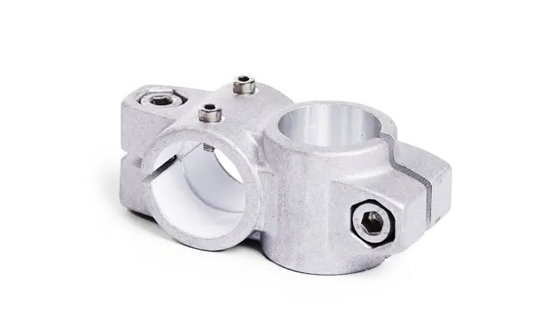
Structural Frames & Architectural Systems
Used in tube joints, clamps, railings, modular structures.
Core benefit: Lightweight structural rigidity and corrosion resistance.
12. Cast Aluminum Tube Connector — vs. Alternatives
Below is a focused, engineering-oriented comparison of cast aluminum tube connectors against the common alternative materials and manufacturing routes.
| Material / Process | Density (g/cm³) | Typical Tensile Strength (MPa) | Temperature Capability (°C) | Corrosion Performance | When to Choose |
| Cast Aluminum (A356, A356-T6) | ~2.68 | 180–320 | 120–180 | Good atmospheric; fair chemical | Weight-critical structures; medium-pressure systems (<30–50 bar); integrated cast geometries |
| Die-Cast Aluminum (A380/ADC12) | ~2.74 | 150–260 | 100–120 | Fair | Mass-production parts; thin-wall connectors; low/medium-pressure applications |
| Wrought Aluminum (6061-T6 / 7075-T6) | 2.70–2.81 | 300–570 | 150–200 | Good | High-cycle fatigue applications; repeated assembly; higher-pressure fittings |
| Forged / Machined Steel (Carbon/Alloy) | ~7.85 | 400–900 | 250–450 | Poor without coating | High-pressure hydraulics; heavy-duty mechanical joints; safety-critical connectors |
Stainless Steel Castings (CF8/CF8M/1.4408, Duplex) |
7.7–8.1 | 450–700 | 300–600 | Excellent; marine-grade | Chemical, marine, offshore; corrosive fluids; when strength + corrosion are required |
| Brass / Bronze Castings | 8.3–8.9 | 200–500 | 200–300 | Excellent in potable water & seawater | Plumbing; marine connectors; stable threaded joints |
| Engineering Plastics (Nylon, PPS, PEEK) | 1.1–1.6 | 70–140 | 80–260 | Excellent chemical; non-conductive | Low-pressure fluid handling; chemical-resistant, non-metallic connectors |
| Metal Additive Manufacturing (AlSi10Mg, 316L, Ti64) | 2.7 (Al) / 4.5 (Ti) / 8.0 (SS) | 250–500 | 100–600 | Good to excellent | Complex internal passages; low-volume specialty connectors; rapid development |
13. Conclusion
Cast aluminum tube connectors combine manufacturing economy and design flexibility with favorable material properties.
Selecting the right alloy and casting method, designing for uniform sections and effective feeding, planning robust joining and sealing strategies, and implementing appropriate quality control steps are the keys to successful, reliable connector production.
Tradeoffs among cost, strength, finish, pressure capability and corrosion resistance must be balanced for the intended service; prototype testing and supplier collaboration are essential before scale-up.
FAQs
Which aluminum alloy is best for a pressure-rated tube connector?
For pressure-rated connectors requiring post-processing and strong mechanical performance, A356 (permanent-mold, T6 if heat treated) is a good choice.
For very high volumes and thin features, A380/ADC12 die-casting may be selected but you must control porosity and validate pressure performance.
Can cast aluminum connectors be welded?
Yes, but with care. Welding cast aluminum requires appropriate filler metal and joint design; porosity and distortion risk mean welded assemblies often require post-weld machining and inspection.
How do I ensure a cast connector is leak-tight?
Use appropriate finishing (machining flat sealing faces), O-ring grooves, impregnation if porosity exists, and validate with hydrostatic or pressure-decay testing at the specified test pressure.
Is anodizing recommended for cast connectors?
Anodizing improves corrosion resistance and appearance but requires good as-cast integrity and pre-treatment; porous castings may need impregnation or sealing before anodize.
What inspection methods detect internal porosity in cast connectors?
X-ray or CT scanning provides detailed internal porosity maps; radiography and ultrasonic testing can detect larger voids; helium pycnometry and destructive metallography quantify porosity fraction.