1. Introduction
Casting is one of humanity’s oldest and most versatile manufacturing processes.
At the heart of this process lies the casting pattern: a physical template that defines the geometry of the final part.
A well-designed pattern minimizes scrap, shortens lead time, reduces machining and improves repeatability; a poor one forces expensive repairs, rework or even a tooling redesign.
2. What Is a Casting Pattern and Why It Matters
A casting pattern is a precisely engineered three-dimensional model of a desired component, used to form the mold cavity into which molten metal is poured.
Unlike a simple replica, the pattern is deliberately modified to incorporate allowances for shrinkage, machining, and distortion, as well as functional features such as gating systems, risers, and core prints.
Once metal solidifies within the mold, it assumes the geometry and dimensions defined by the pattern—making the pattern the foundation of dimensional accuracy and repeatability in casting.
Why Patterns Are Indispensable
In modern foundry practice, the pattern is not just a “template” but an engineering control element that determines casting quality, cost, and process efficiency.
Its impact can be quantified across three core dimensions:
- Geometry Control: Patterns ensure parts match design specifications. A poorly designed pattern can lead to dimensional errors, which cause 35% of casting defects.
- Cost Efficiency: Pattern material and design account for 10–25% of total casting costs.
Choosing the right pattern (e.g., wood for low volume vs. metal for high volume) can reduce per-part costs by 40–60%. - Process Compatibility: No single pattern works for all casting methods—investment casting requires wax patterns, while sand casting uses wood or metal. Mismatched patterns lead to 20% higher scrap rates.
Patterns vs. Dies: A Technical Distinction
While patterns and dies serve similar geometric replication purposes, their operational roles differ fundamentally:
| Feature | Casting Pattern | Die (Permanent Mold) |
| Process Type | Expendable mold (sand, investment, shell) | Permanent mold (die casting, gravity casting) |
| Reusability | Mold destroyed after each casting | Reused for multiple cycles |
| Material | Wood, resin, wax, or metal | Hardened tool steel or H13 |
| Primary Function | Shape and allowance definition for expendable molds | Direct metal forming and cooling control |
| Cost Range | Low-to-medium | High (precision-machined) |
3. Key Design Parameters That Apply to All Patterns
Regardless of material, process, or complexity, every casting pattern must incorporate a set of core design parameters to ensure dimensional accuracy, manufacturability, and defect-free castings.
These principles are guided by ASTM A802 – Standard Specification for Casting Patterns and Core Boxes and are adjusted according to the base metal, casting process, and part geometry.
| Design Parameter | Definition | Typical Values (by Metal/Process) | Rationale / Impact |
| Draft Angle | Taper applied to vertical surfaces to facilitate pattern removal from the mold. | Sand casting: 1–3° Shell molding: 0.5–1° (smoother mold surfaces) | Reduces mold damage (sand cracking or shell breakage) and minimizes pattern wear. Insufficient draft is a leading cause of misaligned or broken molds. |
| Shrinkage Allowance | Extra material incorporated to compensate for contraction during solidification and cooling. | Aluminum alloys: 1–2% Cast iron: 2–3% Brass/copper alloys: 3–4% | Ensures final part dimensions meet design specifications. For example, a 100 mm cast iron part may require a 102–103 mm pattern to compensate for shrinkage. |
| Machining Allowance | Extra material provided to accommodate post-casting machining, finishing, or surface treatments. | Precision components (aerospace/medical): 0.5–1 mm Structural/industrial: 1–2 mm | Facilitates finishing operations, maintains tolerance, and mitigates casting surface imperfections such as roughness or minor porosity. |
Dimensional Tolerance |
Allowable variation in pattern dimensions relative to nominal size. | Metal patterns: ±0.1–0.3 mm Wood patterns: ±0.3–1.0 mm Wax patterns (investment casting): ±0.05–0.2 mm | Ensures consistent production quality and interchangeability, critical for assemblies like automotive gears or aerospace components. |
| Gating Integration | Incorporation of sprues, runners, gates, and risers to control metal flow and feed solidification. | Gate cross-section: 1.5× thickest part section Risers: 2× part volume | Optimizes molten metal delivery, prevents defects like cold shuts, misruns, and shrinkage porosity. Correct gating design can reduce scrap rates by 15–25%. |
| Parting Line | The plane along which the mold splits (e.g., cope vs. drag) to allow pattern removal. | Aligned with symmetry and natural undercuts; avoids trapped features | Simplifies mold assembly, minimizes flash, and reduces machining or rework. Poor parting line placement can increase scrap by up to 20%. |
4. Pattern Materials — selection and trade-offs
| Material | Typical use | Strengths | Weaknesses | Typical life |
| Wood (hardwoods) | Prototypes, low-volume, simple shapes | Cheap, fast to mill, easy repairs | Sensitive to moisture, limited precision | Tens–hundreds of shots |
| Aluminum | Medium volume, match-plate prototypes | Lightweight, good thermal stability, faster cycle | Prone to wear vs steel | Hundreds–thousands of shots |
| Steel / Tool steel | High-volume, precision, hot-run tooling | Durable, excellent dimensional stability | Higher initial cost, harder to modify | Thousands–tens of thousands of shots |
| Cast iron | Heavy-duty match plates, robust patterns | Good thermal mass, low cost vs steel | Heavy, can corrode | Thousands of shots |
| Plastics / Epoxy / PU | Low–medium volume, 3D-printed patterns | Low cost for complex shapes, easy to iterate | Lower thermal stability, abrasion | Tens–hundreds of shots |
| 3D-printed resin / metal | Complex geometry, quick-turn prototypes | No tooling lead time, complex features | Surface finish and strength vary, cost per part | One-offs to low-run reuse |
5. Common Types of Pattern in Casting
Casting patterns are the cornerstone of mold creation. Selecting the correct pattern type balances complexity, volume, cost, and precision.
The following ten patterns are most widely used in industrial casting, with guidance on when and why to choose each.
Single-Piece (Solid) Pattern
- Definition: A single, solid replica of the final part, representing its exact external geometry.
Typically used for small or simple components, it does not have separable sections, and all mold cavities must be formed around this one piece.
It is often used for flat, prismatic shapes where undercuts or complex features are minimal.
Single Piece Pattern - Use Case: Small, simple geometries or prototype parts.
- Advantages: Low cost, easy to fabricate, fast lead time.
- Limitations: Unsuitable for complex geometries or undercuts; may require excessive draft or additional cores.
Two-Piece (Split) Pattern
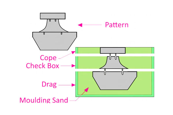
- Definition: A pattern divided along a single parting plane into two halves—commonly referred to as cope (top) and drag (bottom).
This allows the pattern to be removed from sand or other mold materials without damaging the cavity.
The split accommodates moderate undercuts and facilitates gating and riser placement. - Use Case: Most standard sand castings with moderate complexity.
- Advantages: Supports undercuts, allows easy mold removal.
- Limitations: Requires careful parting-plane design and alignment (dowel pins often used).
Multi-Piece Pattern
- Definition: A pattern composed of three or more sections to capture intricate or deep cavities, or to accommodate multiple parting planes.
Components typically include top, bottom, and intermediate sections. This design allows production of complex shapes that cannot be formed with a single or two-piece pattern.Multi-Piece Pattern - Use Case: Complex industrial components with internal features.
- Advantages: Enables casting of deep or multi-directional features without multiple cores.
- Limitations: Assembly is time-consuming; alignment errors may increase scrap.
Match-Plate Pattern
- Definition: Patterns (single or multiple) are mounted on a rigid metal plate, with the cope and drag sides arranged on opposite faces.
This configuration is tailored for mechanized or high-volume molding, allowing automatic flask handling and rapid cavity formation. - Use Case: Medium-to-high volume production in automated sand molding lines.
- Advantages: High repeatability, fast molding, suitable for mechanized production.
- Limitations: Higher initial tooling cost; plate must be machined precisely.
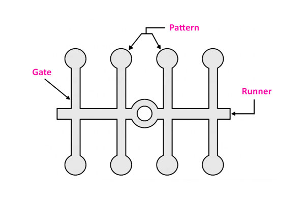
Gated / Multi-Cavity Pattern
- Definition: Combines multiple part patterns into a single assembly, with integrated sprues, runners, and gates.
Designed to fill several cavities simultaneously with molten metal. Often used when identical parts are required in high volume.Gated / Multi-Cavity Pattern - Use Case: Small castings produced in high volumes, e.g., automotive components.
- Advantages: Efficient production, consistent filling, reduced labor per part.
- Limitations: Complex gating design; runner scrap must be recycled.
Skeleton Pattern
- Definition: A simplified, open-frame version of the final component, outlining the key geometric features while leaving large portions of the cavity to be formed by sand or molding material.
This design is particularly effective for large, relatively simple shapes where material savings and sand removal efficiency are important. - Use Case: Large, simple geometries like machine bases or structural castings.
- Advantages: Saves material and weight, simplifies sand removal.
- Limitations: Not suitable for fine detail or small, intricate parts.
Sweep Pattern
- Definition: A pattern that forms a cavity by rotating a profile template (sweep) around a central axis, tracing the desired contour in the mold material.
Ideal for rotationally symmetric components and shapes that can be generated by a single curved profile. - Use Case: Rotationally symmetric parts such as cones, bells, or large pulleys.
- Advantages: Fast cavity formation for axisymmetric geometries.
- Limitations: Limited to sweepable profiles; not suited for complex 3D features.
Loose-Piece Pattern
- Definition: A pattern with detachable sections specifically designed to form undercuts, projections, or internal features.
Loose pieces are removed individually during mold formation to prevent damage to the mold and ensure accurate cavity creation. - Use Case: Parts with bosses, holes, or complex protrusions that trap a one-piece pattern.
- Advantages: Facilitates removal and reduces risk of mold damage.
- Limitations: Requires skilled labor for assembly and precise alignment.
Cope & Drag (Flask) Pattern
- Definition: A modular pattern designed for use in flask-based sand molds, separating the top (cope) and bottom (drag) for easier mold filling, compaction, and metal pouring. Common for large or heavy castings.
- Use Case: Large sand castings such as engine blocks or pump housings.
- Advantages: Modular; supports heavy molds and large parts.
- Limitations: Handling and alignment of heavy flasks can be challenging.
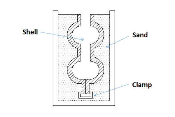
Shell Pattern
- Definition: Used in shell molding processes, often metallic or heated, to produce thin, rigid, resin-bonded sand shells around the pattern.
This type of pattern allows high precision, intricate detail, and excellent surface finish due to controlled heating and uniform shell deposition.Shell Pattern - Use Case: Precision components requiring thin walls, excellent surface finish, or fine detail (e.g., aerospace housings, gearboxes).
- Advantages: High dimensional accuracy (±0.1 mm possible), smooth surface finish (Ra 0.8–3.2 µm), efficient cooling.
- Limitations: Requires process control and careful pattern heating; higher upfront cost than sand patterns.
Engineering Insights
- Pattern choice is dictated by: part geometry, production volume, tolerance requirements, and material.
- Cost vs. complexity trade-off: Simple single-piece patterns are cheapest, while multi-piece or match-plate patterns have higher initial cost but enable high-volume, precise production.
- Pattern maintenance: Reusable patterns (metal) require periodic inspection; expendable patterns (wood, wax) must be replaced frequently to maintain tolerances.
6. Process-Specific Notes: Patterns for Key Casting Methods
Different casting processes impose unique requirements on patterns. Understanding these distinctions ensures optimal mold formation, minimal defects, and cost-effective production.
The following notes detail how patterns are adapted for sand casting, shell molding, investment casting, and die casting.
Sand Casting
- Pattern Requirements: Patterns must be robust yet lightweight, as they are manually or mechanically packed with sand.
Draft angles, shrinkage allowances, and gating features are critical to compensate for sand compaction and metal shrinkage. - Common Pattern Types: Single-piece, two-piece, multi-piece, skeleton, and cope & drag patterns are most widely used.
- Considerations:
-
- Wood patterns are common for low-volume parts; metal patterns are preferred for high-volume or precise components.
- Draft angles typically range from 1–3° for vertical surfaces.
- Core placement and removable pieces are important for undercuts.
- Applications: Engine blocks, pump housings, structural components, and industrial machinery.
Shell Molding Casting
- Pattern Requirements: Patterns must withstand heat for resin-coated sand shell formation. Metal or heated patterns are often used to ensure uniform shell thickness and detail.
- Common Pattern Types: Shell patterns, match-plate patterns, and gated/multi-cavity patterns are ideal.
- Considerations:
-
- Thin shells allow for precise tolerances (±0.1 mm) and smooth surface finishes (Ra 0.8–3.2 µm).
- Draft angles can be smaller (0.5–1°) due to resin flexibility.
- Patterns are often coated to prevent sticking and facilitate release.
- Applications: Aerospace components, precision automotive parts, and small-to-medium intricate industrial castings.
Investment Casting
- Pattern Requirements: Patterns are typically wax replicas of the final part. Wax patterns must be dimensionally accurate and able to withstand multiple coating and burnout cycles.
- Common Pattern Types: Single-piece, gated/multi-cavity, and loose-piece patterns are most frequently employed.
- Considerations:
-
- High dimensional precision and intricate detail are achievable (±0.05–0.2 mm).
- Patterns must account for shrinkage of both metal and ceramic shell.
- Wax patterns can be assembled into trees to cast multiple parts simultaneously.
- Applications: Turbine blades, medical devices, jewelry, and high-precision aerospace components.
Die Casting
- Pattern Requirements: Die casting uses permanent metal dies, not expendable patterns, but dies perform the pattern function of defining part geometry.
Die design must consider part ejection, cooling channels, and gating systems. - Common Pattern Types: Match-plate or gated/multi-cavity concepts are adapted into die tooling.
- Considerations:
-
- High initial cost is offset by rapid, high-volume production.
- Tolerances are tight (±0.1 mm), with minimal finishing required.
- Complex geometries may require slide cores or inserts.
- Applications: Automotive components, electrical housings, consumer electronics, and small precision industrial parts.
7. Conclusion
Choosing the right type of pattern and material is a cost-quality tradeoff that must be resolved at the design stage.
Use simple patterns for prototypes and low volumes, match-plate or gated systems for medium volumes, and steel tool patterns for very high runs.
Combine solid pattern fundamentals (draft, shrinkage, machining allowance) with modern tools (CAD, simulation, 3D printing) to reduce iterations and ramp production faster.
A systematic approach to pattern selection reduces scrap, shortens lead time, and delivers predictable part quality.
FAQs
How big a draft angle should I use?
Use 1°–3° for most polished surfaces. Increase to 2°–5° for textured or coarser sands, and up to 7° for heavy textures.
What shrinkage allowance do I use for stainless steel?
Typical linear allowance is 1.9%–2.5%; confirm with foundry and adjust after trial castings.
When is a match-plate pattern justified?
A: When automation and high repeatability are required—usually hundreds to tens of thousands of parts per year. Break-even depends on tooling cost vs. expected volume.
What is the typical lifespan of a metal pattern?
Aluminum patterns last 10,000–100,000 cycles (medium volume), while steel patterns endure 100,000–1,000,000 cycles (high volume, e.g., automotive mass production).
Can 3D-printed patterns replace traditional metal patterns?
For low-to-medium volume (<10,000 parts), yes—3D-printed patterns reduce lead time by 70–90%.
For high volume (>100k parts), metal patterns remain superior due to their durability and lower per-part cost.