1. Introduction
A gate valve is a fundamental isolation device in industrial fluid systems.
Their long-stroke, linear gate creates a near-unobstructed flow path when fully open and a positive mechanical seal when fully closed.
Because of low pressure drop, robust construction and suitability for very large sizes and high pressures, gate valves remain a go-to choice for pipeline isolation in industries ranging from water and power to oil & gas and mining.
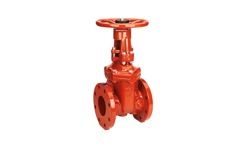
2. What is a Gate Valve?
A gate valve is a type of linear motion valve that uses a sliding gate or wedge-shaped disc to start or stop the flow of a medium.
Unlike throttling valves that regulate flow, gate valves are primarily designed for on/off isolation.
When fully open, they create a nearly unobstructed flow path with minimal pressure drop, which makes them highly efficient for bulk flow systems such as pipelines, water distribution networks, or oil & gas transmission lines.
Gate valves are available in a wide range of diameters — from DN 15 (½ inch) to DN 1200 (48 inches) and beyond for custom pipeline solutions.
They are also manufactured for pressure ratings up to Class 2500 (PN 420), making them suitable for both low-pressure water services and high-pressure, high-temperature steam or hydrocarbon systems.
Because of their robustness and adaptability, gate valves are among the most widely specified valves across industries like energy, chemical processing, mining, construction, and water management.
Key Features of Gate Valves
- Low Pressure Drop: Full-port gate valves (port diameter = pipe diameter) have ΔP 50–70% lower than globe valves of the same size.
For example, a 6-inch full-port gate valve has a flow coefficient (Cv) of 1,200, vs. 600 for a 6-inch globe valve (ASME B16.104). - High Flow Capacity: Ideal for large-diameter systems (up to 120 inches) handling high flow rates (e.g., 5,000 gpm for water mains), where maximizing throughput is critical.
- Cost Efficiency: For diameters ≥6 inches, gate valves are 20–30% cheaper than ball valves and 50% cheaper than butterfly valves, making them the economical choice for bulk fluid transport.
- Robust Sealing: Wedge-shaped gates self-seal under pressure, achieving ISO 5208 Class IV (metal seats) or Class VI (soft seats) shutoff—critical for preventing fluid loss in toxic or high-value applications.
- Wide Operating Range: Suitable for pressures from vacuum to ANSI Class 2500 (4,200 psi) and temperatures from -196°C (cryogenic) to 870°C (high-temperature steam), depending on materials.
3. Design Components & Materials of Gate Valves
Gate valves are engineered as pressure boundary devices that combine structural strength, sealing integrity, and material compatibility to ensure safe isolation.
Their design elements and materials are chosen carefully to meet performance, safety, and cost requirements across industries.
Main Components of a Gate Valve
| Component | Function | Typical Design Considerations |
| Body | Primary pressure boundary housing fluid and guiding flow. | Designed to withstand full pressure rating; manufactured by casting or forging; includes end connections (flanged, welded, threaded). |
| Bonnet | Covers the valve internals and supports stem/actuator assembly. | Bolted, welded, or pressure-seal bonnet types depending on service pressure. |
| Gate (Disc/Wedge) | Sliding barrier that isolates flow. | Options include solid wedge, flexible wedge, slab gate, or parallel discs; choice depends on pressure, temperature, and thermal cycling. |
| Seat Rings | Provide sealing interface between gate and valve body. | Hardfaced with alloys (Stellite, Inconel) or soft-seated for bubble-tight sealing. |
Stem |
Transmits motion from actuator/handwheel to gate. | Rising-stem (visible motion) or non-rising (compact); surface hardened or coated to resist wear. |
| Packing & Gland | Prevents leakage along stem. | Made of graphite, PTFE, or advanced low-emission packings; live-loading improves sealing reliability. |
| Gaskets & Fasteners | Seal body-bonnet joint. | Spiral wound gaskets, metallic seals; high-strength bolting for integrity under pressure and temperature cycles. |
| Actuator / Handwheel | Provides mechanical or powered operation. | Manual (handwheel, gearbox) or automated (electric, pneumatic, hydraulic) depending on size and service. |
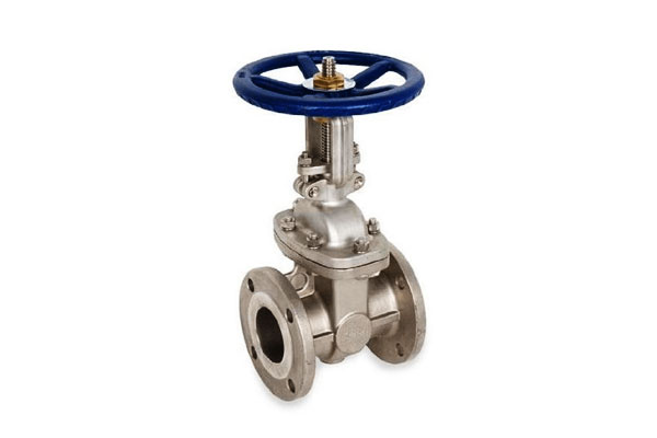
Material Selection for Gate Valves
Choosing the correct material is essential to ensure mechanical strength, corrosion resistance, and thermal stability.
| Component | Common Materials | Application Notes |
| Body & Bonnet | Cast iron, ductile iron, carbon steel (WCB), stainless steel (CF8/CF8M), Cr-Mo steels, duplex/super-duplex, nickel alloys | Carbon steel for general service; stainless/duplex for corrosive environments; Cr-Mo for high-temperature steam; cast iron for cost-effective water service. |
| Gate (Disc) | Same as body or upgraded alloys; hardfaced with Stellite or equivalent | Hardfacing improves wear and sealing durability. |
| Seat Rings | Stainless steel, hardfaced alloys, soft inserts (PTFE, elastomers) | Soft seats for bubble-tight sealing in low-temp services; hardfaced alloys for high-temp, erosive service. |
Stem |
Stainless steel, high-strength alloy steel, Monel, Inconel | Corrosion-resistant alloys prevent galling and stem leakage under severe service. |
| Packing | Graphite, PTFE, braided carbon fiber | Graphite for high temperature (> 400 °C); PTFE for low-friction, chemical resistance. |
| Gaskets | Spiral wound (SS + graphite), metal ring joint (RTJ), compressed fiber sheets | Selected based on pressure class, media compatibility, and emission standards. |
4. Working Principle of Gate Valves
A gate valve operates by translating rotational motion (handwheel or actuator) into linear motion of the stem and gate. Key behaviours:
- Open: Rotating the actuator retracts the gate into the bonnet/slot, creating an unobstructed flow path approximating pipe bore. Flow resistance is low, and pressure drop is minimal.
- Close: The gate advances into the seat area, compressing against one or two seats to isolate flow. Seat contact is metal-to-metal or metal-to-soft material depending on design.
- Guidance & sealing: Guides and seat geometry prevent tilting, ensure even seating, and compensate for thermal expansion (flexible wedge designs).
- Position indication: Rising-stem designs provide visual confirmation of open/closed position; non-rising stems often use indicators or limit switches.
5. Types of Gate Valves
Gate valves can be classified in several ways — by wedge geometry, stem configuration, or specialized design variations.
The correct selection depends on fluid type, pressure, temperature, cycle frequency, and installation space.
Wedge (Solid, Flexible) vs. Parallel Gates
| Type | Description | Advantages | Limitations | Common Applications |
| Solid Wedge | One-piece, rigid gate with tapered sealing faces. | Simple, robust, suitable for most services. | Sensitive to thermal distortion; not ideal for high-temp cycling. | Water, oil, gas pipelines, low-to-medium pressure service. |
| Flexible Wedge | Similar to solid wedge but with a thin relief groove or hollow section that allows slight flexing. | Compensates for seat misalignment and thermal expansion; better sealing in steam and thermal cycling services. | Slightly weaker than solid wedge; manufacturing complexity. | Power plants, steam service, high-temp pipelines. |
| Parallel Gate | Two flat, parallel discs pressed against seats by spring or fluid pressure. | Low operating torque; good sealing; less risk of jamming under thermal stress. | Higher cost; more complex design. | High-pressure pipelines, refineries, and hydrocarbon service. |
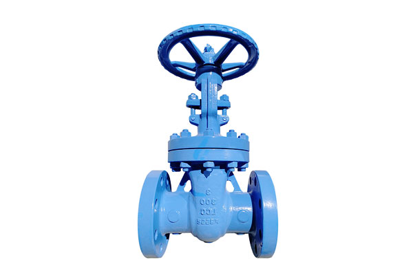
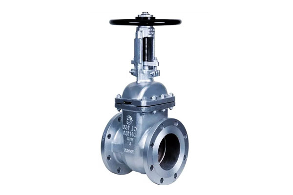
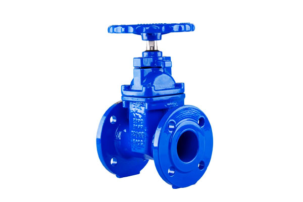
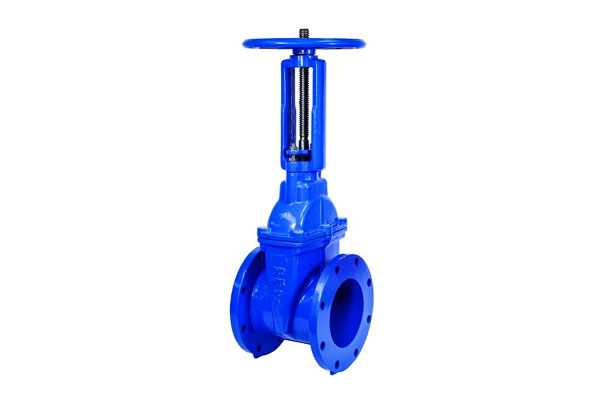
Rising-Stem (OS&Y) vs. Non-Rising-Stem
| Type | Description | Advantages | Limitations | Typical Applications |
| Rising Stem (OS&Y – Outside Screw & Yoke) | Stem threads external to fluid; stem visibly rises/falls as valve operates. | Clear visual position indication; threads isolated from process medium, reducing corrosion. | Requires more vertical space; exposed threads need lubrication and protection. | Power plants, refineries, aboveground installations requiring visual verification. |
| Non-Rising Stem | Stem rotates in place; gate moves via internal thread engagement. | Compact design; suitable for confined or buried spaces. | No visual position indication (requires indicator or limit switch); stem threads exposed to medium. | Underground pipelines, shipboard, compact installations. |
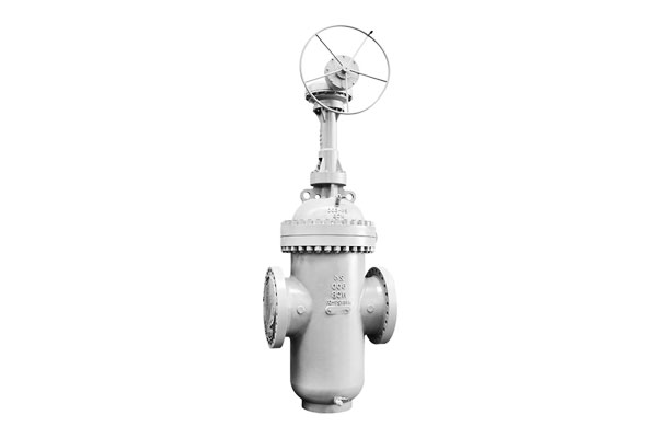
Through-Conduit, Slab, and Knife Gate Variations
| Type | Description | Advantages | Limitations | Applications |
| Through-Conduit Gate Valve | Gate retracts fully into body cavity, creating an unobstructed, full-bore flow path. | Full-bore design enables pigging; low pressure drop; ideal for long-distance pipelines. | Larger body size; higher cost; more complex maintenance. | Oil & gas transmission, slurry pipelines, petrochemical service. |
| Slab Gate Valve | A single, flat gate that slides across the bore; often used in through-conduit designs. | Simple structure; tight shutoff; easy operation. | Not self-cleaning; debris may accumulate in seat area. | High-pressure, large-diameter pipelines, hydrocarbons. |
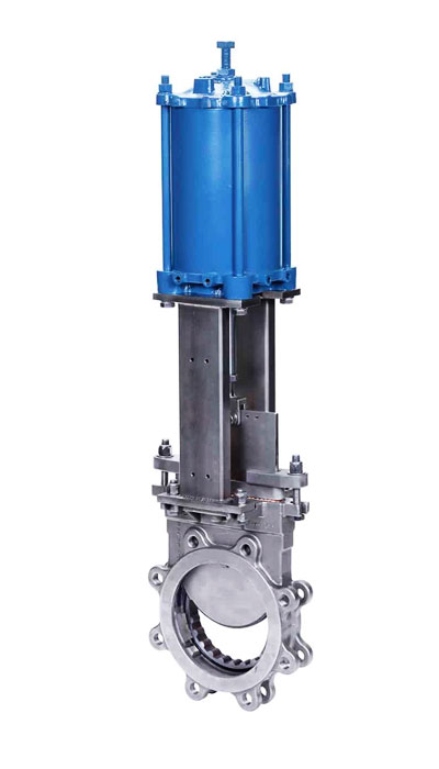
| Knife Gate Valve | Thin, sharpened gate that cuts through slurry or solids. | Handles thick, viscous, or abrasive fluids; low cost; lightweight. | Lower pressure ratings; less reliable sealing than wedge/parallel gates. | Mining, pulp & paper, wastewater, bulk solids transport. |
6. Common Manufacturing Processes of Gate Valves
The manufacturing of gate valves requires a combination of heavy-duty forming processes (casting, forging, fabrication) and precision machining to achieve sealing accuracy.
Each route is selected based on valve size, pressure class, material, and application requirements.
Overview of Manufacturing Routes
| Process | Description | Advantages | Limitations | Typical Applications |
| Casting | Molten metal is poured into a mold to form valve body/bonnet. Common methods: sand casting, shell molding, investment casting. | Economical for complex shapes and large sizes; wide material choice. | Casting defects (porosity, shrinkage) require NDT inspection; machining required for finish. | Large-diameter water/gas valves; carbon steel or stainless steel bodies. |
| Forging | Metal shaped under pressure to refine grain structure and strength. | Superior mechanical properties; high density; less risk of defects. | More costly for large sizes; limited to smaller–medium valves. | High-pressure steam, oil & gas, refinery services. |
| Fabrication & Welding | Valve body built from rolled plates or forged sections welded together. | Flexibility for very large or custom valves; lower material waste. | Requires weld qualification, PWHT, and NDT; welding adds cost. | Extra-large diameter water/gas distribution valves, offshore. |
CNC Machining |
Precision finishing of body, gate, stem, and sealing surfaces. | High accuracy and repeatability; ensures sealing tolerances. | Time- and cost-intensive; requires advanced equipment. | All gate valves (final finishing). |
| Surface Treatment & Hardfacing | Deposition of alloys (e.g., Stellite, Inconel) on seats/gates; coatings for corrosion resistance. | Extends life, improves erosion and corrosion resistance. | Adds process complexity and cost. | High-temp steam, corrosive/erosive services. |
| Assembly & Testing | Installation of internals, packing, gaskets, and actuator; followed by hydrostatic and seat leakage tests per API/ISO. | Ensures functional integrity and compliance with standards. | Labor-intensive; requires skilled QA/QC. | All final products. |
Casting Processes and Tolerances
| Casting Method | Description | Typical Size Range | Dimensional Tolerance* | Notes |
| Sand Casting | Uses expendable sand molds; most common for large valve bodies. | DN 50 – DN 1200+ | ±2.5–3.0 mm per 100 mm | Flexible, economical, but rougher finish. |
| Shell Molding | Fine sand bonded with resin; thin shell molds. | DN 15 – DN 300 | ±1.5–2.0 mm per 100 mm | Better surface finish; moderate complexity. |
| Investment Casting (Lost Wax) | Wax pattern coated with ceramic, then molten metal poured. | DN 15 – DN 150 | ±0.5–1.0 mm per 100 mm | Excellent precision; limited to small/medium valves. |
Quality Assurance in Manufacturing
- Non-Destructive Testing (NDT): Radiographic, ultrasonic, magnetic particle, or dye penetrant testing to detect casting/forging defects.
- Hydrostatic & Seat Leakage Testing: Performed according to API 598, ISO 5208, or MSS-SP-61 standards.
- Material Certification: Mill Test Reports (MTRs) confirm chemical composition and mechanical properties.
- Dimensional Control: CNC machining ensures sealing faces achieve required roughness (Ra ≤ 0.8 μm typically).
7. Key Performance Characteristics and Typical Data Ranges
These ranges are typical guidance engineers use when specifying gate valves; always confirm with manufacturer data for exact ratings.
| Characteristic | Typical Range / Example |
| Sizes (nominal) | DN 15 (½”) up to DN 1200 (48″) and larger for special pipeline valves |
| Pressure Ratings | ANSI/ASME Classes 150 → 2500 (PN10 → PN420 approx.) |
| Temperature Range | Cryogenic (≤ −196 °C with suitable materials) to > 550 °C (Cr-Mo alloys) |
| End Connections | Flanged (ASME B16.5/B16.47), butt-weld, socket-weld, threaded |
| Typical Leakage Class | Metal-to-metal: higher leakage than resilient; resilient seat: bubble-tight where permitted |
| Typical Torque | Small valves: handwheel (≤ 200 N·m); large/high-pressure: gearboxes or actuators (hundreds to thousands N·m) |
| Cycle Duty | Designed for infrequent to moderate cycles; not intended for high-frequency modulating service |
| Expected Service Life | 10–25+ years depending on duty, materials and maintenance |
8. Common Failure Modes and Root-Cause Mitigation
| Failure mode | Typical causes | Mitigation |
| Seat leakage | Erosion, debris, improper seating force, seat damage | Install strainers/filters; hardface seats; ensure correct seating force; regular inspection |
| Gate sticking / jam | Corrosion, solid buildup, distorted gate | Material selection (corrosion resistant); design for cleanability; periodic cycling |
| Packing failure / stem leakage | Improper packing, aging, thermal cycling | Use appropriate packing (graphite for high temp); live-loading to maintain compression; scheduled replacement |
| Stem thread wear / galling | Over-torque, corrosion, poor lubrication | Anti-galling coatings, correct lubrication, torque limiters |
| Bonnet leakage | Gasket degradation, bolt relaxation | Use proper gasket material and torque sequence; re-torque where permitted |
| Erosion / cavitation | Partial opening throttling, two-phase flow | Avoid throttling with gate valves; use erosion-resistant trims; install anti-cavitation features or change valve type |
9. Industry Applications of Gate Valves
Gate valves are widely used where isolation and low pressure drop are priorities:
- Oil & Gas / Pipelines: Bulk isolation, piggable pipeline valves (API 6D), tank bottom valves.
- Power Generation: Main steam isolation, feedwater lines, turbine bypass and boiler drains (high temp and high pressure).
- Water & Wastewater: Large diameter flow isolation, dam outlets and distribution mains (ductile iron valves common).
- Petrochemical & Refining: Hydrocarbon isolation, high-pressure process lines (Cr-Mo and stainless variants).
- Mining & Minerals: Slurry isolation (knife gates preferred for abrasive slurries).
- Marine & Offshore: Ballast and cargo isolation; materials selected for seawater corrosion resistance.
- Industrial Manufacturing: General process isolation in chemical plants, pulp & paper and food industries (resilient seats where sanitary closure is required).
10. Comparison with Other Valve Types
Gate valves are widely used for on/off isolation, but engineers and procurement managers often need to weigh them against other valve types — such as globe, ball, butterfly, and check valves — to optimize cost, performance, and maintainability.
Functional Comparison
| Criterion | Gate Valve | Globe Valve | Ball Valve | Butterfly Valve | Check Valve |
| Primary Role | Isolation (on/off) | Throttling & flow regulation | Quick shutoff & tight sealing | Large-diameter isolation & throttling | Prevents backflow |
| Flow Path | Straight-through, full bore | S-shaped, tortuous | Straight-through (full or reduced bore) | Disc in centerline of flow | Automatic, flow-actuated |
| Pressure Drop (Fully Open) | Very low | High | Very low | Low–moderate | Low–moderate |
| Shutoff Tightness | Good (metal or resilient seats) | Excellent | Excellent (bubble-tight with soft seats) | Good (soft seats better) | Excellent (depending on design) |
| Throttling Suitability | Poor (causes erosion, vibration) | Excellent | Moderate (possible in V-port ball valves) | Limited | Not designed for throttling |
| Operation | Multi-turn (slow) | Multi-turn (moderate) | Quarter-turn (fast) | Quarter-turn (fast) | Automatic, no manual actuation |
Size Range |
Small to very large (up to DN 1200+) | Small to medium (≤ DN 600 typical) | Small to medium (≤ DN 600 typical, larger possible) | Medium to very large (up to DN 4000) | Wide range depending on type |
| Actuation | Manual, gearbox, electric, pneumatic, hydraulic | Manual, electric, pneumatic | Manual, electric, pneumatic | Manual, electric, pneumatic | Self-actuated (no external control) |
| Maintenance | Moderate–high (packing, seat wear) | Moderate (trim replacement) | Low–moderate (seat wear in high-cycle service) | Low (compact design) | Low (replace disc/spring) |
| Typical Pressure Rating | ANSI 150–2500 | ANSI 150–2500 | ANSI 150–2500 | ANSI 150–600 | ANSI 150–2500 |
| Cost (relative) | Moderate (increases with size/pressure) | Higher (more material-intensive) | Moderate–high (larger bores expensive) | Economical for large diameters | Low–moderate |
Key Takeaways
- Gate valves are best for isolation where low pressure drop and large sizes are required, but not for throttling.
- Globe valves are the top choice for precise flow control and throttling duties.
- Ball valves offer quick shutoff with excellent sealing, making them popular in oil & gas, chemical, and general industrial use.
- Butterfly valves provide a compact, lightweight, and economical solution for very large diameters, often in water or HVAC systems.
- Check valves serve a different function altogether: preventing backflow in piping systems without external control.
11. Innovation, Digitalization, and Sustainability Trends
The gate valve industry is evolving to meet demands for smarter, more sustainable, and higher-performance solutions. Below are the most impactful trends:
Digitalization (Smart Gate Valves)
- IoT-Enabled Monitoring: Valves equipped with pressure, temperature, and vibration sensors (e.g., Siemens Sitrans VP) transmit real-time data to plant SCADA systems.
AI algorithms predict failures (e.g., seat wear) 2–3 months in advance, reducing unplanned downtime by 30%. - Remote Actuation: 5G-enabled electric actuators (e.g., Emerson Bettis) allow remote operation of subsea or hazardous-area valves, eliminating the need for on-site personnel and reducing safety risks.
- Digital Twins: Virtual replicas of gate valves (e.g., AVEVA E3D) simulate performance under variable pressure/temperature, optimizing maintenance schedules and reducing overhauls by 20%.
Advanced Materials
- Ceramic Composites: Silicon carbide (SiC)-coated gates and seats improve abrasion resistance by 5x, extending service life in mining slurries from 3 to 15 years.
- High-Temperature Alloys: Hastelloy C276 bodies and Inconel X-750 stems enable gate valves to operate in 800°C+ environments (e.g., nuclear power plants), expanding their use beyond traditional limits.
- Self-Healing Polymers: PTFE seats embedded with microcapsules release sealant when damaged, reducing leakage and extending seat life by 3x.
Sustainability
- Recycled Materials: 80–90% recycled steel is used in gate valve bodies, reducing energy consumption by 40% vs. primary steel (World Steel Association).
- Low-Leakage Designs: Live-loading packing and PTFE seats reduce fugitive emissions by 90%, complying with strict environmental regulations (e.g., EPA Method 21, EU REACH).
- Energy Efficiency: Full-port gate valves reduce pump energy use by 15–20% vs. reduced-port designs, aligning with global carbon reduction goals (e.g., net-zero by 2050).
12. Conclusion
Gate valves are a stalwart of industrial fluid handling: simple in principle, but demanding in specification and application.
Their advantages — low pressure drop, wide size and pressure capability, and reliable mechanical isolation — make them the right choice for many critical isolation duties.
Successful deployment requires matching valve type and materials to service conditions, avoiding misuse (notably throttling), enforcing robust manufacturing and testing, and instituting a risk-based maintenance program.
Modern trends — actuator intelligence, advanced alloys, digital monitoring and additive manufacturing — improve reliability and lifecycle economics, but the core requirement remains:
specify gate valves conservatively, maintain them proactively, and treat them as long-lived safety and process assets.
FAQs
Can gate valves be used to throttle flow?
No. Gate valves are designed for on/off isolation. Partial opening causes high-velocity jets, seat erosion and vibration. Use globe or control valves for throttling.
What is the difference between a flexible and solid wedge gate?
A flexible wedge has a thin section that allows elastic bending to maintain seal under thermal cycling or minor misalignment; a solid wedge is rigid and used where distortion is minimal.
How often should large gate valves be exercised?
Exercise frequency depends on duty; a common practice is periodic operation (monthly to quarterly) for infrequently used isolation valves to prevent sticking — high-criticality valves require a formal inspection schedule.
What packing is recommended for high-temperature steam service?
Graphite packing or high-temperature braided carbon fiber packings are standard for steam; live-loading is recommended to maintain seal over long intervals.
When is a knife gate preferred?
Knife gates are preferred for slurries and solids-laden fluids where a thin gate can sever deposits and provide isolation; however, they usually have less sophisticated sealing than wedge or parallel-seat designs.

