1. Introduction
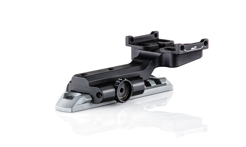
Investment casting (lost-wax) is an excellent production route for stainless steel mount brackets that need complex geometry, attractive finishes and reliable mechanical performance.
For medium to high mix volumes, the process delivers near-net shapes, tight tolerances, and the ability to cast a wide range of stainless alloys (304/316, duplex, 17-4PH, 904L, etc.).
Properly executed, investment-cast brackets reduce part count, minimize welding, and offer superior aesthetic and corrosion performance versus alternative methods.
2. Why choose Investment Casting for Stainless Steel Mount Bracket?
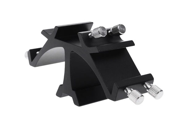
Investment casting (lost-wax) is often the best manufacturing route when mount brackets must combine complex geometry, corrosion resistance, good surface finish, and repeatable dimensional control.
Core engineering advantages
Design freedom (near-net complexity)
- Undercuts, internal pockets, thin ribs, integrated bosses and fillets can be produced in one piece without welding or assembly.
- This reduces part count, eliminates welded joints (and their corrosion/strength issues) and shortens assembly cycles.
Hydraulic / load-path optimization
- Brackets that carry complex load vectors or must match contoured mating surfaces benefit from near-net casting: stress-flow-conforming shapes and integral ribs raise stiffness without added machining.
Material & alloy flexibility
- Investment casting accepts a wide range of stainless alloys (304/316/316L, 17-4PH, 2205/2507 duplex, 904L) and nickel-based grades, letting you match corrosion and strength to environment.
Surface finish & appearance
- Typical as-cast finishes are Ra ≈ 1.6–3.2 μm, often good enough for many visible applications.
With mechanical polishing or electropolishing you can reach Ra ≤ 0.4 μm (mirror finish) for architectural hardware.
Dimensional accuracy & repeatability
- Typical as-cast tolerances of ±0.1–0.3 mm (small features) mean much less machining than sand casting. Repeatability across batches supports consistent fit and interchangeability.
Material utilization & reduced secondary machining
- Near-net shapes cut raw-material waste dramatically versus machining from forgings/billet.
Typical material savings vs full-machining: 30–70% depending on geometry. Post-cast machining is limited to critical features (bores, faces), often reducing total cycle cost.
3. Typical Stainless Alloy for Brackets
| Alloy | Type | Typical Tensile (MPa) | Yield (MPa) | Corrosion Highlights | When to specify |
| 304 | Austenitic | 520–750 | 205–250 | General corrosion resistance | Interior architectural brackets |
| 316 / 316L | Austenitic (Mo) | 520–750 | 205–250 | Improved pitting resistance vs. 304 | Marine, food, medical |
| 17-4PH | Precipitation-hardening | 850–1,100 (aged) | 650–950 | High strength; moderate corrosion | Load-bearing, aerospace brackets |
| 2205 (Duplex) | Duplex SS | 650–900 | 450–600 | Excellent chloride/Pitting resistance | Offshore, chemical exposure |
| 2507 (Super duplex) | Super Duplex | 800–900 | 550–700 | Exceptional pitting & SCC resistance | Aggressive seawater/chemicals |
| 904L | Super-austenitic | 600–750 | 250–350 | Superior resistance to reducing acids | Chemical process brackets |
4. Design for Investment Casting (DfIC)
Good DfIC reduces scrap and final machining. Key rules for mount brackets:
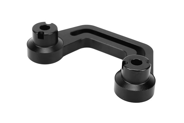
- Uniform section thickness: avoid abrupt transitions; ideal section 2.0–6.0 mm depending on load. Thin walls (<1.5 mm) are risky for stainless alloys.
- Radii and fillets: internal fillet ≥ 1–2× local thickness to avoid hot spots and stress risers. Sharp corners cause shrinkage and cracking.
- Draft: add 1–2° draft where wax removal or pattern pull is needed (helps wax tooling life).
- Bosses & mounting pads: design with machining allowance (0.5–1.5 mm) when critical flatness or tapped threads needed; include radius at boss-to-web junction.
- Knockouts and core-backs: use internal cores or collapsible features to produce recesses or undercuts.
- Hole & thread strategy: for high precision threaded holes specify machined holes and tapped or helicoil inserts; for non-critical holes cast near-net and finish drill.
- Gating & feeding: place gates to feed heavy bosses/hubs; avoid gating across thin ribs or V sections to prevent porosity.
5. Investment Casting Process Flow for Stainless Steel Mount Bracket
The investment casting process for mount brackets involves 10 sequential steps, each with critical control points to ensure dimensional accuracy and material integrity:
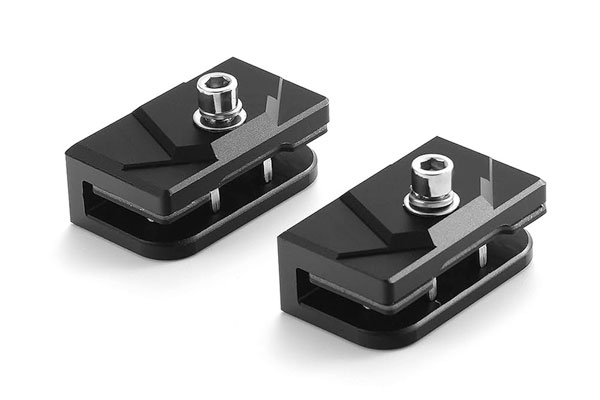
5.1 Master Model Fabrication
- Process: CNC-machine an aluminum/steel master (tolerance ±0.02 mm) or 3D-print (SLA) a resin master for complex brackets (e.g., lattice structures).
- Control Points: 3D scan the master to verify geometry (deviation ≤0.05 mm); ensure mounting holes/ribs align with CAD specs.
5.2 Wax Tooling Production
- Process: Create a two-piece metal mold (P20 steel) from the master; add gating channels (sprue, runners) sized for stainless steel flow (gate width = 1.5× bracket’s thickest section).
- Control Points: Mold cavity surface finish Ra ≤0.8 μm (ensures smooth bracket surfaces); gate location at non-load-bearing areas (e.g., bracket base) to avoid post-trim damage.
5.3 Wax Pattern Injection
- Process: Inject molten wax (paraffin-synthetic blend, 60–80°C) into the mold under 15–25 MPa pressure for 20–40 seconds.
- Control Points: Wax temperature ±2°C (prevents pattern distortion); injection pressure ±1 MPa (ensures full filling of thin ribs).
- Inspection: 5% of patterns tested via CMM for hole position (±0.05 mm) and wall thickness (±0.03 mm).
5.4 Wax Assembly (Treeing)
- Process: Attach 10–20 wax bracket patterns to a wax sprue (10–12 mm diameter); orient brackets to minimize air trapping (e.g., holes upward).
- Control Points: Sprue-to-pattern connection strength (5 N pull test); pattern spacing ≥5 mm (ensures uniform shell coating).
5.5 Ceramic Shell Building
- Primary Coat: Dip the tree in a zircon-alumina slurry (particle size 1–3 μm) + zircon sand (40–60 mesh); dry 6–8 hours (40–60% humidity).
- Backup Coats: 4–6 layers of silica slurry (particle size 20–50 μm) + silica sand (80–120 mesh); dry 8–10 hours per layer.
- Control Points: Final shell thickness 5–8 mm (varies by bracket size); shell strength tested via compressive load (≥4 MPa).
5.6 Dewaxing (Burnout)
- Process: Heat the shell to 900–1,000°C in a vacuum furnace for 2–3 hours to vaporize wax.
- Control Points: Heating rate 50°C/hour (prevents shell cracking); final temperature ±25°C (ensures 100% wax removal).
5.7 Shell Firing
- Process: Fire at 1,100–1,200°C for 2–3 hours to sinter the ceramic.
- Control Points: Hold time ±15 minutes (avoids under-sintering/over-sintering); shell permeability tested via air flow (≥8 L/min at 0.1 MPa).
5.8 Stainless Steel Melting & Pouring
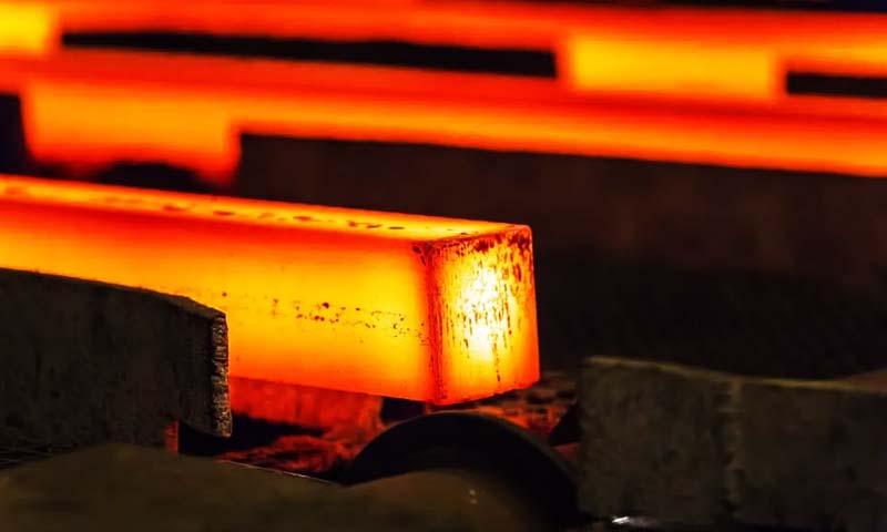
- Melting: Use VIM (critical brackets) or induction melting (industrial brackets) to melt stainless steel (1,500–1,600°C for 304/316L).
- Pouring: Preheat the shell to 800–900°C; pour molten steel via gravity (simple brackets) or vacuum (complex/low-volume brackets).
- Control Points: Pouring temperature ±20°C (ensures fluidity); fill time 5–15 seconds (avoids cold shuts in thin ribs).
5.9 Cooling & Solidification
- Process: Cool the shell in air (304/316L) or a controlled atmosphere (17-4 PH/duplex 2205) to 200–300°C over 4–8 hours.
- Control Points: Cooling rate 50–100°C/hour (reduces thermal stress; bracket warpage ≤0.3 mm).
5.10 Shell Removal & Trimming
- Process: Vibrate or water-jet (0.3–0.5 MPa) to break the shell; cut gates/risers via laser (±0.1 mm accuracy) or band saw (±0.5 mm).
- Control Points: Gate removal 0.5–1.0 mm from the bracket (avoids surface damage); no burrs on mounting holes (critical for fastener fit).
6. Melting, Pouring, and Heat-Treatment
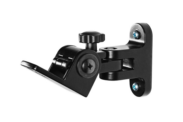
Melting & Pour
- Melt cleanliness: induction melting with argon shroud or VIM (for critical alloys) reduces inclusions and gas pickup. Aim for low oxygen and sulfur levels.
- Pour temperature: stainless alloys poured ~1,450–1,600 °C depending on composition (316L ~1,450–1,520 °C).
Excess superheat increases oxidation; too low causes misruns in thin sections. - Degassing: argon purging minimizes hydrogen porosity.
Heat treatment
- Austenitics (304/316): solution anneal ~1,040–1,100 °C, rapid quench to dissolve carbides and restore corrosion resistance.
- Precipitation hardening (17-4PH): solution treat ~1,040 °C then age at 480–620 °C per required temper to achieve yield/tensile.
- Duplex & super duplex: careful solution anneal (1,050–1,120 °C) and rapid quench to preserve phase balance; avoid extended holds in 600–950 °C to prevent sigma phase.
Control points: avoid sensitization in austenitics (450–850 °C range) and sigma phase in duplex; record heat-treatment cycles and check microstructure if service critical.
7. Post-casting Operations: Machining, Assembly features, and Surface finishing
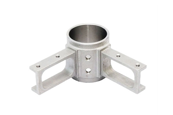
Machining & assembly prep
- Critical bores: ream to H7 (typical tolerance ±0.01–0.02 mm) and check concentricity.
- Threads & inserts: preferred practice: machine bosses for helicoil or PEKK inserts rather than casting threads in thin material.
- Mating faces: mill flat faces to specified flatness (0.05–0.2 mm depending on size).
Surface finishing
- Shot blasting / bead blast: uniform matte finish (Ra ~1.6–3.2 µm).
- Mechanical polishing & buffing: reduce Ra to 0.2–1.0 µm for architectural or sanitary brackets.
- Electropolishing: removes micro-asperities (Ra ≤0.4 µm) and improves corrosion resistance — recommended for marine/medical brackets.
- Coatings / plating: PVD, nickel plating, or powder coating for color/appearance/extra corrosion protection — ensure compatibility with stainless substrate and environmental regs.
Assembly & welding
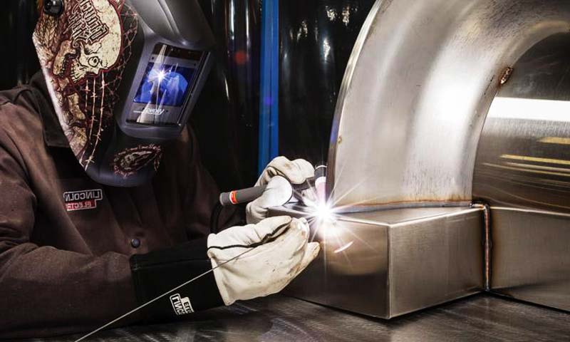
- Investment casting reduces welds but sometimes requires small welds for studs or inserts; use low heat input and post-weld passivation to prevent heat tint corrosion.
8. Tolerances, Surface Roughness & Dimensional Control
| Item | Typical As-Cast | After Finish Machining |
| Linear tolerance (≤25 mm) | ±0.1–0.2 mm | ±0.01–0.05 mm |
| Linear tolerance (25–100 mm) | ±0.2–0.5 mm | ±0.02–0.1 mm |
| Flatness (mounting face) | 0.2–0.5 mm | 0.02–0.1 mm |
| Pin/Hole tolerance | Ø +0.2 / −0.3 mm (cast) | H7 ±0.01–0.02 mm (reamed) |
| Surface roughness Ra | 1.6–3.2 µm (as-cast) | 0.05–0.8 µm (polished/electropolished) |
| Shrinkage allowance | Linear 1.5–2.0% (stainless typical) | n/a |
9. Quality Assurance
Inspection methods
- Dimensional: CMM measurement for critical geometry and hole patterns.
- Surface roughness: profilometer readings for finish spec.
- Visual & penetrant testing (PT): surface crack detection.
- Radiography / CT (RT): internal porosity or inclusions in critical brackets.
- Ultrasonic testing (UT): thicker sections or castings with limited RT access.
10. Common Failure Modes and Mitigation Strategies
| Failure Mode | Cause | Mitigation |
| Corrosion / pitting | Wrong alloy or poor passivation in chloride environment | Specify 316L/duplex/2507 or 904L; electropolish & passivate |
| Fatigue at mount points | Stress concentrations, sharp corners | Add fillets, increase local section, shot peening |
| Porosity-initiated cracks | Gas pickup, poor gating | Argon degassing, optimized gating/riser, RT inspections |
| Distortion after welding | High heat input at studs or attachments | Low-heat welding, post-weld stress relief & passivation |
| Surface blemishes / heat tint | Improper finishing or welding | Proper cleaning, pickling, and passivation |
11. Industry Applications & Case Examples
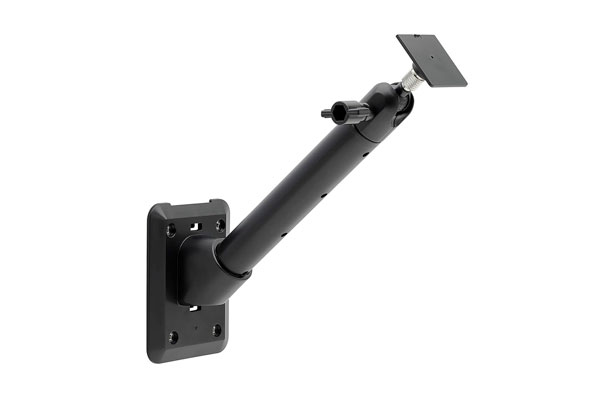
Stainless steel mount bracket produced via investment casting are widely used across industries that demand structural reliability, corrosion resistance, and high dimensional accuracy.
Key Industry Applications
| Industry | Typical Application | Alloy Choice | Key Requirements |
| Automotive & Heavy Vehicles | Mounting brackets for turbochargers, exhaust systems, and suspension components | 304, 316, 17-4PH | Heat resistance, vibration fatigue strength, corrosion protection |
| Marine & Offshore | Deck equipment mounts, railing supports, winch brackets, pump/motor supports | 316L, Duplex 2205, Super Duplex 2507 | High chloride corrosion resistance, pitting resistance (PREN > 35), seawater durability |
| Aerospace & Defense | Engine mounting brackets, landing gear hinge mounts, UAV payload brackets | 17-4PH, 15-5PH | High strength-to-weight, fatigue life, dimensional precision |
| Construction & Architecture | Structural hardware for glass facades, balustrades, handrails, curtain wall brackets | 304, 316, 904L | Aesthetic finish (mirror polish), atmospheric corrosion resistance, load safety |
Energy & Power Generation |
Pump impeller supports, turbine casing brackets, solar tracking mounts | Duplex 2205, Inconel 625 | High-temperature resistance, stress corrosion cracking prevention, long service life |
| Medical & Pharmaceutical | Equipment frames, cleanroom mounting brackets, surgical bed supports | 316L, 17-4PH | Biocompatibility, cleanability, corrosion resistance in sterilization environments |
| Rail & Public Transport | Brackets for suspension, HVAC systems, and carriage interiors | 316L, Duplex | Fatigue resistance, vibration dampening, low-maintenance finish |
12. Comparison with Other Manufacturing Methods
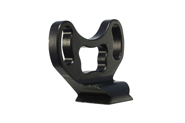
Stainless steel mount bracket can be produced using several methods: investment casting, forging, stamping, machining, and welded fabrication.
Each process offers unique advantages and trade-offs in terms of cost, design flexibility, surface quality, and performance.
Comparative Table
| Manufacturing Method | Advantages | Limitations | Typical Applications |
| Investment Casting | – Complex geometries with internal ribs and contours- Near-net shape → reduces machining by up to 70%- Excellent surface finish (Ra 1.6–3.2 µm, mirror-polish achievable)- Material flexibility: 304, 316L, 17-4PH, Duplex, 904L, etc.- Consistent quality for medium-to-high volumes | – Higher unit cost for very simple parts- Longer lead time for tooling and shell building (2–3 weeks) | Aerospace, marine, automotive, architecture (high-spec, complex brackets) |
| Forging | – Superior mechanical strength due to grain flow- Suitable for high-stress brackets- Good fatigue resistance | – Limited geometry complexity (mostly solid or simple shapes)- Requires significant machining afterward- Higher tooling costs | Heavy-duty industrial brackets, load-bearing supports |
Stamping & Forming |
– Cost-effective for thin-walled, high-volume parts- Fast cycle times (seconds per part)- Minimal post-processing for simple shapes | – Restricted to sheet geometries- Requires welding for complex 3D shapes (weaker joints)- Limited alloy thickness range | Consumer goods, light architectural hardware |
| Machining (from bar/plate) | – Excellent precision (±0.01 mm possible)- Flexible, no tooling cost for low volumes- Ideal for prototyping or custom parts | – High material waste (up to 60%)- Long machining times for complex designs- Expensive for medium/high volumes | Low-volume aerospace, custom machinery mounts |
| Welded Fabrication | – Low upfront cost, no casting/mold tooling- Flexible for oversized or custom parts- Easy to modify or repair | – Weld seams prone to fatigue and corrosion- Requires polishing and finishing- Dimensional repeatability lower than casting/forging | Structural supports, large equipment frames |
Key Insights
- Strength vs. Complexity: Forging yields the highest strength due to grain refinement, but investment casting enables more complex bracket geometries with weight-optimized ribbing.
- Surface Finish & Aesthetics: Investment casting outperforms welding and stamping for architectural brackets where mirror-polished surfaces are required.
- Cost Efficiency: For high-volume, thin-walled brackets, stamping is the cheapest, but for medium-volume, complex 3D shapes, investment casting provides the best balance of cost and performance.
- Lifecycle Value: Investment-cast stainless steel brackets, especially in marine, aerospace, and architectural applications, offer longer service life and lower maintenance, justifying their higher initial cost.
13. Cost, Lead time, and Production-volume considerations
- Tooling cost: wax tooling typically $3k–$20k; amortize over order quantity.
- Per-part cost: competitive for medium volumes (100s–10,000s). Very low volumes (<50) may favor machining or 3D printed prototypes.
- Lead time: prototype samples 2–6 weeks (depending on tooling method and finishing). Production runs: several weeks depending on batch size and finishing steps.
- Economics tip: run an NRE amortization analysis (tooling + setup ÷ part qty) to compare manufacturing routes.
14. Conclusion
Investment casting is a compelling production method for stainless steel mount bracket when geometry complexity, surface quality, and alloy selection matter.
By following DfIC best practices, controlling melt and pour variables, and performing appropriate post-casting operations (precision reaming, electropolishing, passivation), manufacturers can deliver robust, attractive, and long-lived brackets for demanding applications.
For each project, evaluate part volume, critical tolerances, alloy choice and finish requirements to confirm investment casting is the optimal route.
FAQs
Minimum viable order for investment casting?
There’s no universal minimum, but tooling cost means investment casting is most economical for medium to high volumes.
Rapid prototyping (3D printed wax/resin) lowers upfront costs for small runs.
Can I cast threaded holes directly?
You can, but cast threads in thin walls are weak. The common practice is to cast a boss and machine/tap or install helicoils/inserts for strength and repeatability.
What finish should I request for marine brackets?
Electropolish + passivation on 316L or select duplex/super-duplex materials; Ra ≤0.4 µm is typical for long life in chloride environments.
How much machining allowance should I design?
Provide 0.5–1.5 mm mach. allowance on critical faces and bores; specify reamed/tapped final dims on the drawing.
How to prevent distortion in welded cast brackets?
Minimize welding by design, use low heat input processes, tack as needed, stress relieve and then perform finish machining as final step.
