1. Introduction:
Rooted in the craftsmanship of ancient civilizations, lost-wax casting has evolved significantly, from bronze statues of antiquity to the aerospace-grade components of today.
While the foundational principles of shaping metal via a wax prototype have remained, the processes and materials involved have undergone a transformation that reflects modern engineering precision.
Among the innovations driving this evolution, silica sol investment casting stands out as a superior advancement.
Leveraging colloidal silica binders, this technique enhances surface quality, dimensional accuracy, and high-temperature stability—all while promoting environmental sustainability.
As industries demand increasingly complex and high-performance metal components, silica sol casting has become the method of choice for delivering tight tolerances and metallurgical integrity in a wide range of applications.
2. What Is Silica Sol Lost Wax Casting
Silica Sol Lost Wax Casting is an advanced investment casting process that leverages colloidal silica as the primary binder in the ceramic shell mold.
This method combines the precision of traditional lost wax casting with the enhanced performance of silica sol, a stable suspension of silicon dioxide (SiO₂) nanoparticles dispersed in water.
Unlike conventional binders like water glass (sodium silicate) or ethyl silicate, silica sol offers superior dimensional accuracy, surface finish, and environmental sustainability.
It is ideal for high-precision components in aerospace, medical, and industrial applications.
What Makes Silica Sol Special?
The silica sol binder consists of nano-sized amorphous silica particles (typically 10–20 nm) suspended in water.
Compared to other binder systems (like sodium silicate or phosphate), silica sol offers:
- Dimensional accuracy: Achievable tolerances up to ±0.1–0.2% of linear dimensions, consistent with ISO 8062 CT4–CT6 standards for small-to-medium-sized components.
- Surface finish: Typical as-cast roughness (Ra) ranges from 1.6–3.2 μm, significantly better than the Ra 12.5–25 μm common in sand or water glass casting.
- Shell strength and stability: The silica sol binder imparts excellent green and fired strength, with thermal resistance exceeding 1300 °C.
3. Core Process Overview: From Wax to Precision Metal
Silica sol casting is a multistage manufacturing process designed to transform a wax replica into a high-performance metal component with exceptional precision.
Each step is critical to achieving the dimensional accuracy, surface quality, and structural soundness required by advanced industries such as aerospace, medical devices, and energy systems.
Let’s walk through each phase of the process in sequence:
Wax Pattern Creation
The journey begins by producing a wax model of the final part. These patterns are typically formed by injecting molten wax into an aluminum die, ensuring exact replication of the desired geometry.

- Typical tolerance on wax patterns: ±0.05 mm
- Wax shrinkage compensation: Accounted for during mold design
- Batch capability: One wax tree may carry 30–100 parts depending on size
Multiple wax patterns are assembled onto a central wax sprue, forming a “tree” that allows simultaneous casting of several components.
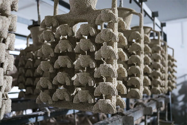
Shell Building with Silica Sol Slurry
The assembled wax tree is dipped into a ceramic slurry, composed of colloidal silica binder and fine refractory particles such as zircon flour.
Each dip is followed by a layer of stuccoing, where coarser refractory grains are applied to build up strength.

- Coating cycles: 6 to 10 layers
- Drying time per layer: 4 to 6 hours
- Final shell thickness: 7–15 mm, depending on metal type and casting size
This step is repeated until a durable, heat-resistant shell is formed. Environmental control (temperature 22–28 °C, RH < 50%) is vital to prevent shell warping or delamination.
Dewaxing the Shell
Once the shell has fully dried, the entire assembly is subjected to dewaxing, a critical step for cavity formation.
The most common method is steam autoclaving, where high-pressure steam (typically 7–10 bar) melts and drains out the wax.
- Temperature: 160–180 °C
- Time: 20–30 minutes
- Wax recovery rate: Up to 90% recyclable
This process removes wax cleanly without damaging the fragile ceramic shell.
Shell Firing and Preheat
After dewaxing, the shell is fired in a furnace to burn off residual wax, vitrify the shell, and prepare it for metal casting.
- Ramp-up temperature: 400–600 °C
- Soak at peak: 1000–1100 °C for 2–4 hours
- Outcome: Strengthens the shell, increases thermal shock resistance
Firing also transforms the amorphous silica into crystalline phases (like cristobalite), enhancing shell integrity and thermal insulation.
Metal Melting and Pouring
The fired shell, still hot, is filled with molten metal. Melting is done in vacuum or induction furnaces, depending on alloy type.
Superheat levels must be tightly controlled to ensure proper flow and solidification.
| Alloy Type | Pouring Temp | Superheat |
|---|---|---|
| Stainless Steel | 1510–1550 °C | 60–80 °C |
| Inconel | 1380–1420 °C | 20–40 °C |
| Aluminum | 690–740 °C | 30–50 °C |
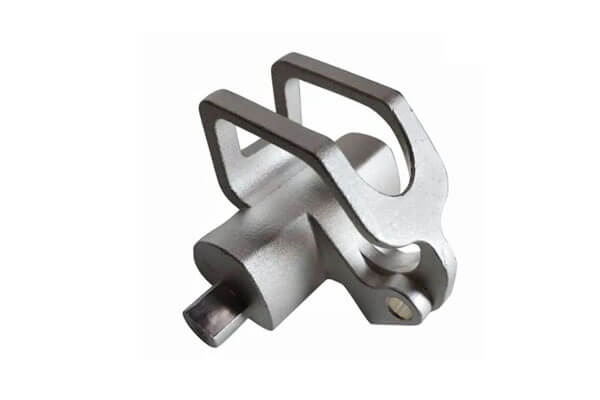
Shell Removal and Finishing
Once the metal solidifies and cools, the ceramic shell is mechanically broken away using vibration, high-pressure water jets, or grit blasting.
After shell removal, sprues and gates are cut off, and the casting is cleaned and finished.
Common finishing steps:
- Shot blasting
- Heat treatment (e.g., solution annealing)
- CNC Machining (if required)
- Surface passivation or coating
Silica Sol Lost Wax Casting Complete process video >>
4. Materials, Binders, and Additives: Engineered for Performance
In silica sol investment casting, material science plays a central role in achieving high precision, durability, and metallurgical integrity.
Each component of the shell system—from the silica sol binder to the refractory materials and additives—is carefully selected and engineered to withstand extreme thermal, chemical, and mechanical conditions.
Let’s break down the critical components and their performance contributions.
Silica Sol Binder – The Core of the Ceramic Shell
At the heart of the process is the silica sol binder, a stable colloidal suspension of nano-sized amorphous silica particles (typically 10–20 nm) dispersed in water.
This binder provides the structural matrix for the ceramic shell.
Key properties of silica sol:
| Property | Typical Value |
|---|---|
| SiO₂ content | 30–40% by weight |
| pH range | 9.0–10.5 |
| Particle size | 10–20 nm |
| Viscosity | 5–15 cP |
| Free silica content | < 0.1% (advantageous for safety) |
Performance Benefits:
- Excellent thermal stability: resists deformation up to 1600 °C
- Low shrinkage: improves dimensional accuracy
- Good wetting behavior: enhances slurry adherence to wax patterns
- Environmentally safer: water-based, low VOC emissions
Refractory Materials – Shell Strength and Heat Resistance
The silica sol is combined with refractory fillers to form the slurry that coats the wax pattern.
These materials define the shell’s thermal resistance, chemical inertness, and mechanical strength.
Common primary and backup refractories:
| Material | Function | Typical Use |
|---|---|---|
| Zircon flour | Prime coat | Excellent thermal shock resistance, smooth finish |
| Alumina | Backup layers | High-temperature resistance, economical |
| Fused silica | Lightweight insulation | Low thermal expansion |
Rheology Modifiers & Wetting Agents – Slurry Stability
To maintain consistency and performance during shell building, manufacturers incorporate additives into the silica sol slurry.
Key additives include:
- Rheology modifiers: Adjust viscosity to prevent slurry sedimentation (e.g., bentonite, attapulgite clay)
- Wetting agents: Improve flow and adhesion of the slurry onto wax (e.g., non-ionic surfactants)
- pH stabilizers: Ensure colloid stability over time
- Biocides: Inhibit microbial growth during storage
Wax and Pattern Materials – Compatible and Clean-Burning
The wax patterns themselves must be dimensionally stable, low-ash, and compatible with the silica sol binder system. Typical waxes are formulated from a blend of:
- Paraffin
- Microcrystalline wax
- Resin modifiers
Ash content should be below 0.05% to avoid contamination. In some cases, expandable polystyrene (EPS) is used for large or simple geometries, requiring different dewaxing and shell-building considerations.
Secondary Coatings and Layering Strategy
The shell is built in stages, with different materials used for different layers:
- Prime coat: High-purity zircon or alumina with fine particle size (~1–10 µm) for superior surface quality
- Intermediate coats: Blends of zircon and alumina for balanced strength and permeability
- Backup coats: Coarser alumina or fused silica (~50–75 µm) for structural support
The layering strategy is designed to optimize thermal insulation, gas permeability, and mechanical strength without compromising surface fidelity.
5. Dimensional Precision and Surface Quality
In high-performance industries—such as aerospace, medical devices, and industrial machinery—dimensional precision and surface finish are not just quality metrics, but essential performance drivers.
Silica sol lost wax casting, also known as precision investment casting, delivers exceptional results in both categories, enabling near-net-shape parts with minimal post-processing.
Dimensional Precision: Achieving Tolerances with Confidence
Silica sol casting consistently achieves tolerances in the ISO IT7–IT9 range, significantly outperforming traditional sand casting and rivaling certain CNC-machined features.
This is largely due to the process’s excellent replication fidelity from wax pattern to final metal part, aided by the low-shrinkage, thermally stable silica sol shell.
Typical dimensional tolerances:
| Feature Type | Tolerance Range |
|---|---|
| Linear dimensions | ±0.1% to ±0.2% of nominal size |
| Flatness & roundness | ±0.1 mm for features <100 mm |
| Minimum wall thickness | 1.5 – 2.5 mm (depending on alloy and complexity) |
| ISO grade equivalence | IT7 to IT9 |
Surface Quality: Engineered for Smoothness and Detail
Beyond dimensional precision, surface finish is a defining characteristic of silica sol casting.
Thanks to the binder’s fine particle size and use of high-purity zircon or alumina in the prime coat, silica sol castings achieve exceptional smoothness, detail fidelity, and minimal surface defects.
Typical surface roughness values:
| Process Type | Surface Roughness (Ra) |
|---|---|
| Silica sol casting | 0.4 – 1.6 µm |
| Sand casting | 6.3 – 25 µm |
| Machined finish | 0.8 – 1.6 µm |
6. Process Control, Inspection, and Quality Assurance
Ensuring repeatable quality and precision in silica sol lost wax casting requires rigorous process control and comprehensive inspection protocols.
From shell formation to final part evaluation, manufacturers deploy an integrated quality assurance system that addresses both process variation and product conformance.
Robust Process Control: Precision Begins at the Source
Effective quality control starts with the tight management of upstream variables. The silica sol casting process involves numerous interdependent steps, each with its critical parameters.
Maintaining stability across these steps is essential for achieving consistent outcomes.
Key process control elements include:
- Slurry viscosity: Maintained between 10–15 cP to ensure uniform coating
- Drying time: Monitored per layer (typically 8–24 hours) to prevent shell cracking
- Shell thickness: Measured after each dip (target range: 5–10 mm total across 6–9 layers)
- Burnout temperature: Precisely controlled to 950–1050 °C to remove wax residues completely
- Pouring temperature: Kept within ±10 °C of target to avoid misruns or hot tears
These parameters are tracked using SPC (Statistical Process Control) tools, enabling real-time alerts when data trends move out of tolerance windows.
Shell Integrity Monitoring
A structurally sound ceramic shell is vital for successful casting. During shell building, operators conduct several tests to verify strength, permeability, and defect-free layering.
Typical monitoring techniques:
- Ultrasonic testing: Detects delaminations or air gaps between layers
- Shell microscopy: Evaluates uniformity, grain structure, and adherence
- Weight vs. thickness checks: Used to calibrate dipping and stuccoing rates
By identifying inconsistencies before pouring, manufacturers reduce the risk of catastrophic casting failures.
Casting Inspection: From Macro to Micro
Once the metal casting is complete, it undergoes a multi-layered inspection process to verify dimensional integrity, internal soundness, and surface finish.
Common nondestructive and destructive inspection methods:
| Method | Purpose |
|---|---|
| Visual inspection | Detects surface defects (e.g., pitting, cold shuts) |
| Dye penetrant testing (DPT) | Highlights microcracks and porosity on non-ferrous alloys |
| Radiographic testing (X-ray) | Reveals internal defects like shrinkage, inclusions |
| Ultrasonic testing | Evaluates wall thickness and bonding in critical regions |
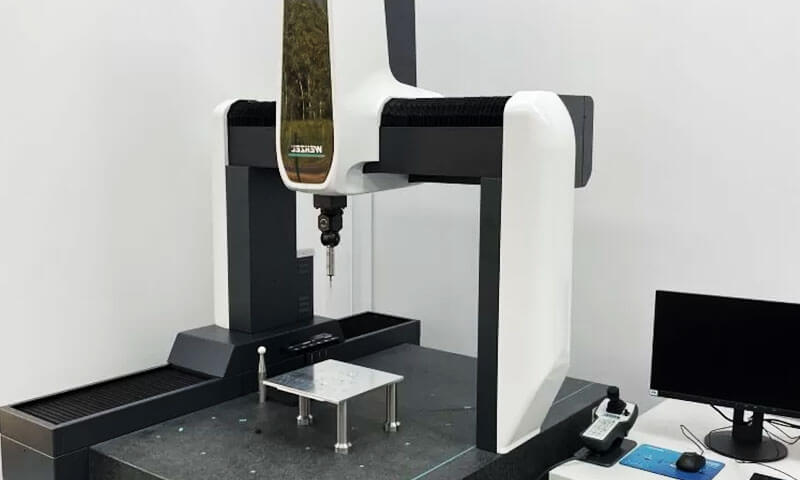
| CMM (Coordinate Measuring Machine) | Verifies dimensional tolerances to ±0.01 mm |
Process Capability and Statistical Quality Metrics
To demonstrate consistent production capability, foundries apply statistical process analysis. Critical dimensions and mechanical properties are evaluated using metrics such as:
- Cp (Process Capability Index): Target ≥ 1.33 for stable processes
- Cpk (Process Performance Index): Target ≥ 1.33 for centered processes
- PPM (Parts Per Million Defect Rate): Industry benchmark for aerospace and medical castings is often < 500 PPM
Such data-driven metrics form the foundation of Six Sigma and AS9100/ISO 13485 certified production systems.
Traceability and Documentation
High-end investment casting operations maintain full traceability of:
- Material heat lots
- Shell batch records
- Wax pattern die histories
- Furnace logs and temperature charts
- Final inspection data sheets
This documentation is essential for regulatory compliance, root cause analysis, and customer audits, especially in the aerospace and medical sectors.
7. Comparison Table: Silica Sol vs. Other Investment Casting Methods
| Criteria | Silica Sol | Phosphate Binder | Water Glass (Sodium Silicate) | 3D-Printed Investment Molds |
|---|---|---|---|---|
| Surface Roughness (Ra) | 0.4–1.6 µm | 2.5–3.2 µm | 6–12 µm | 5–10 µm |
| Dimensional Tolerance | ISO IT7–IT9 | ISO IT9–IT11 | ISO IT11–IT13 | IT10–IT12 (variable) |
| Thermal Resistance | Up to 1,350 °C | Up to 1,200 °C | Limited to ~1,100 °C | Depends on mold material (often < 1,200 °C) |
| Pattern Cost (High Volumes) | Low (reusable wax injection molds) | Low | Very low | High per part (especially with resin) |
| Shell Integrity | Excellent (strong, crack-resistant) | Moderate (brittle at high temp) | Weak (porous, low strength) | Variable (resin burnout may damage shells) |
| Material Compatibility | High-alloys, stainless, superalloys | Carbon, alloy steels | Mainly carbon and low-alloy steels | Depends on shell, typically limited |
| Surface Detail Fidelity | High (excellent for fine features) | Moderate | Low | Medium (depends on print resolution) |
| Best Use Case | Aerospace, medical, precision engineering | Industrial parts, heavy machinery | Low-cost large parts with loose tolerance | Rapid prototyping, design validation |
8. Economic Considerations and Cost-Efficiency
Silica sol lost wax casting is not just about precision—it’s also a calculated choice in balancing performance and cost.
The following table summarizes key economic factors across the casting process:
Economic Comparison Table
| Cost Factor | Silica Sol Casting | Water Glass Casting | Phosphate Binder Casting |
|---|---|---|---|
| Binder Cost | High (30–50% ↑) – due to pure colloidal silica | Low – inexpensive sodium silicate | Medium – lower purity, lower viscosity control |
| Shell Material Cost | High – uses zircon, alumina, fused silica | Low – basic quartz, low-performance fillers | Medium – alumina & silica mix |
| Drying & Shell Building Time | 3–7 days (6–9 layers) | 1–3 days (4–5 layers) | 2–5 days (5–7 layers) |
| Tooling Cost (per mold) | High ($2,000–$10,000), but durable & reusable | Low to moderate | Moderate |
| Pattern Cost per Part | Low for high volume (wax injection) | Low | Low |
| Yield / Material Utilization | High (net-shape, low machining) | Moderate | Moderate |
| Scrap/Rework Rate | Low – excellent shell integrity | Higher – prone to defects | Medium – moderate porosity risk |
| Typical Production Volume | Medium to High | High | Medium |
| Best Use Case | Precision, high-alloy parts | General-purpose, low-cost castings | Heavy-duty industrial castings |
9. Conclusion: The Industry Gold Standard for Complex Precision Parts
In summary, silica sol investment casting represents a convergence of ancient metallurgy and cutting-edge materials science.
With superior dimensional precision, material versatility, and surface quality, it is the go-to method for high-performance, geometrically complex parts in demanding sectors.
Despite higher consumable costs, the method’s ability to produce net-shape, defect-free components ultimately results in lower total cost of ownership and unmatched design freedom
LangHe is the perfect choice for your manufacturing needs if you need high-quality silica sol lost wax casting services.