Over my 30-plus years working the shop floor and mentoring process engineers, I’ve seen too many new practitioners treat machining precision as nothing more than “does the part fit within the tolerance band.”
They look at a dimension on a print, check it with a caliper, and call it good. But precision runs far deeper than that.
From the nominal values on the blueprint to the chips coming off the tool, precision is a multi-layered system of dimensional control, form integrity, and positional alignment — and getting any one layer wrong will derail an entire assembly.
Tương tự, surface quality is often dismissed as “just cosmetic.” I can’t count how many times I’ve heard “it’s inside the machine, nobody sees it” — only to watch those parts wear out 5x faster or crack prematurely from surface-initiated fatigue.
This guide breaks down machining precision into its three core dimensions, walks through the five practical methods we use on the floor to hit dimensional targets, and explains the four ways surface quality directly determines component service life.
This isn’t textbook theory — it’s the lessons we learned one scrapped batch and one failed field trial at a time.
1. The Three Dimensions of Machining Precision
Every tolerance on a blueprint falls into one of three categories: độ chính xác chiều, form accuracy, and positional accuracy.
New engineers often fixate on dimensional numbers and ignore the other two — which is exactly how you end up with parts that “measure right” but don’t work.
Độ chính xác kích thước
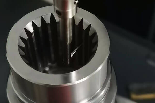
Dimensional accuracy describes how close a single feature’s actual size is to its ideal nominal value — think bore diameter, shaft length, or slot width.
It is the most intuitive and most commonly measured dimension of precision, but it is also the most frequently misinterpreted.
Here’s the first shop floor rule most new folks miss: the nominal dimension on the drawing is the center of the tolerance band, not the upper or lower limit.
If you set your tool offset right at the upper limit just to “make sure it fits,” you’re already halfway to out-of-tolerance as soon as your tool starts to wear.
We always target the nominal value on first cuts, and leave equal margin on both sides for wear.
It sounds basic, but I’ve seen entire batches scrapped because an operator set up at the tolerance edge.
Form Accuracy
Form accuracy describes how true a feature is to its intended geometric shape.
Độ thẳng, độ phẳng, circularity, hình trụ, and line profile tolerance all fall into this category. In plain terms: is the shaft actually round? Is the table top actually flat?
This is the silent killer of assembly performance. I once had a batch of 4140 steel shafts that passed every dimensional diameter check by the book.
But when we pressed bearings onto them, they sang and vibrated so bad we had to scrap the whole run.
The problem? Poor cylindricity — the shaft was slightly oval, by only 0.03 mm, but enough to load the bearing unevenly. Dimensional numbers all passed; form accuracy failed.
Positional Accuracy
Positional accuracy describes the geometric relationship between features: parallelism between two faces, perpendicularity between a bore and a mounting surface, concentricity between two bores, or hole pattern position on a housing.
This is the most expensive kind of precision failure. If the hole pattern on a gearbox housing is shifted by 0.1 mm, the shafts bind, the gears wear prematurely, and the whole unit fails early.
You can’t fix positional error by sanding or reaming — it’s built into the setup.
The Unwritten Shop Floor Hierarchy
There’s an old priority rule we live by, earned through decades of scrapped parts and midnight rework: Form tolerance > Positional tolerance > Dung sai kích thước
Most people assume dimensional tolerance is the tightest, but it’s not. Form is the foundation. If your surface isn’t flat, you can’t measure parallelism accurately.
If your bore isn’t round, your diameter measurement is meaningless. This hierarchy isn’t pulled from a standard handbook — it was learned the hard way.
2. Five Practical Methods to Achieve Dimensional Accuracy
Hitting your dimensional targets isn’t magic — it’s about picking the right method for the volume, sức chịu đựng, và hình học.
We use five core methods on the floor, each with its own personality, strengths, and pitfalls.
Cut-and-Try Method
The classic old-school method: take a light cut, measure the result, adjust your tool offset, and repeat. You sneak up on final size incrementally, never cutting too deep in one pass.
- Tốt nhất cho: One-off parts, Nguyên mẫu, small batch jobs, and very tight tolerances
- Shop floor reality: Chậm, but unbeatable for flexibility. This is the first skill I make every apprentice master, and it takes a good six months to get really good at it.
You develop a feel for how much the tool will deflect, how much heat will make the part grow, and how to read a micrometer like it’s a second language. - Catch: It only works if your operator knows what they’re doing. A bad offset on a finish cut ruins the part.
Setup Adjustment Method
You dial in your tool position and work offset once, then run an entire batch off the same setup.
- Tốt nhất cho: Medium and large production batches, consistent repeat parts
- Thuận lợi: Stable accuracy, Hiệu quả cao, consistent part-to-part quality. This is the workhorse of mass production.
- Critical rule: Always inspect and validate the first piece fully before running the batch.
I’ve seen 500 parts scrapped in an hour because someone skipped first-piece inspection and the tool offset was 0.2 mm off.
Sized Tool Method
You use a tool of a fixed, calibrated size — drills, reamers, broaches, and tap drills all work this way. The hole size is the tool size, more or less.
- Tốt nhất cho: Standard hole sizes, Splines, and internal profiles
- Thuận lợi: Đơn giản, nhất quán, no complex offset management.
- Catch: Tool wear is the silent killer. A reamer that’s worn by 0.02 mm will quietly drift every hole over the run, and you won’t notice until you measure. You have to track tool life and replace on schedule, not on failure.
Tự động & CNC Control Method
CNC and automatic control systems essentially bake the operator’s experience into the program.
The machine measures, compensates for tool wear, and retracts automatically, with precise coordinate control over the tool path.
- Tốt nhất cho: Hình học phức tạp, medium to high volume, consistent repeatability
- Thuận lợi: Far higher efficiency and consistency than manual methods. Complex contours and 3D surfaces that would be impossible by hand are routine on a CNC mill.
- Hard truth: Garbage in, garbage out. If the program is wrong, the machine will just make the mistake faster and more consistently than a human.
I’ve seen more expensive crashes from bad code than from bad operator judgment.
Comparison of Dimensional Control Methods
| Phương pháp | Best Volume Range | Typical Dimensional Accuracy | Hiệu quả sản xuất | Skill Requirement | Primary Risk |
| Cut-and-Try | 1 - 10 pieces | ±0.005 – ±0.02 mm | Rất thấp | Rất cao (6+ months to master) | Human error on final cut |
| Setup Adjustment | 20 - 500+ pieces | ±0.01 – ±0.05 mm | Cao | Vừa phải | First-piece setup error causes batch scrap |
| Sized Tool | 10 - 1000+ pieces | ±0.01 – ±0.03 mm | Medium-High | Thấp | Gradual tool wear drift |
| Tự động & CNC Control Method | 5 - 10,000+ pieces | ±0.005 – ±0.02 mm | Rất cao | Cao (programming skill) | Program error causes rapid, consistent defects |
Bonus: Hình thức & Positional Accuracy Methods
For form accuracy, we rely on three core approaches:
- Path generation: Precision tool path interpolation on CNC machines creates accurate free-form profiles
- Form tooling: Shaped form tools cut the full profile in one pass for consistent cross-sections
- Generating processes: Quay, mài, and honing generate round forms through controlled relative motion
For positional accuracy, the golden rule is non-negotiable: machine all position-critical features in a single setup.
Every time you unclamp and re-fixture the part, you introduce alignment error. If you can drill all the holes in one clamping, do it.
3. Chất lượng bề mặt: The Hidden Driver of Component Service Life
So you’ve hit all your dimensions, your form is good, your positions are dead on. Are you done? Not even close.
That thin top layer of metal — the surface — will make or break the part’s service life. There are four ways surface quality directly impacts performance, and most new engineers only know one of them.
Đang đeo điện trở
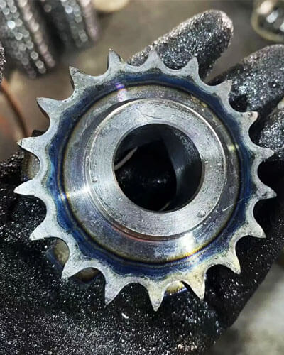
No matter how smooth two mating surfaces look, at the micro level they’re only touching at the peaks of the surface roughness profile.
Higher roughness means fewer, higher contact points, faster initial wear, and longer break-in time.
This is exactly why new engines have a break-in period: you’re wearing down those microscopic peaks so the surfaces mate fully and enter stable wear.
For heavy load applications, surface quality is the difference between 10,000 hours of service and 1,000 giờ. I’ve seen heavy gear sets last 3x longer just by dropping surface roughness from Ra 3.2 to Ra 0.8.
Sức mạnh mệt mỏi
Under cyclic loading, every tiny tool mark, cào, and machining ridge is a stress riser. Fatigue cracks almost always initiate at the surface, at the root of a roughness peak.
Here’s the counterintuitive part: compressive residual stress at the surface is a good thing.
It cancels out a portion of the tensile cyclic load, making cracks harder to initiate and propagate.
Processes like shot peening, roller burnishing, and cold finishing are all designed to deliberately build in a layer of compressive surface stress.
People think they’re just “smoothing the surface” — they’re actually pre-stressing it to last longer.
Kháng ăn mòn
The smoother the surface, the fewer crevices and valleys there are for moisture, chất gây ô nhiễm, and corrosive chemicals to collect. Pitting corrosion starts in the valleys of surface roughness.
Drop the Ra value, and you extend corrosion life dramatically. For parts operating in humid, salty, or acidic environments, a good surface finish can add years of service life with no other design change.
For marine components, moving from Ra 6.3 to Ra 1.6 can double corrosion service life.
Fit & Assembly Stability
This is the most overlooked effect. Two parts with the same nominal interference fit can behave completely different if their surface roughness is different.
Higher roughness means the peaks crush on assembly, giving you less effective actual interference.
Worse: residual stress from machining can relax over time, causing dimensions to shift slightly. I once had a batch of precision bushings that passed every inspection right after machining.
We boxed them up, put them in the warehouse for two weeks, and when we went to assemble them, half of them wouldn’t fit.
Internal residual stress had relaxed, and the sizes had shifted just enough to throw the fit off. Never skip stress relief for precision fit parts.
4. The Bigger Picture: Precision and Quality Are System Indicators
Here’s the biggest lesson I learned over 30 năm: machining precision and surface quality are not isolated, independent metrics. They are the visible output of the entire manufacturing system.
Machine rigidity, Công cụ mặc, cutting heat, internal residual stress, spindle vibration, fixturing accuracy — every single factor in the process shows up in the final part.
If you’re chasing consistent precision, you can’t just “try harder” at the machine. You have to look at the whole system.
Understanding these cause-and-effect relationships — how tool wear shows up in dimensional drift, how cutting speed shows up in surface finish, how fixturing shows up in positional error — is far more valuable than memorizing tolerance tables.
Anyone can look up a tolerance value. The engineer who knows why the tolerance is there, and what affects it, is the one who keeps the line running.
Final Thought
Good machining isn’t about hitting numbers on a print. It’s about understanding what those numbers mean, how they’re created, and how they affect the part when it’s in service.
Master the three dimensions of precision, respect the power of surface quality, and see the whole system behind the chip — and you’ll solve problems before they happen, not after the batch is scrapped.