

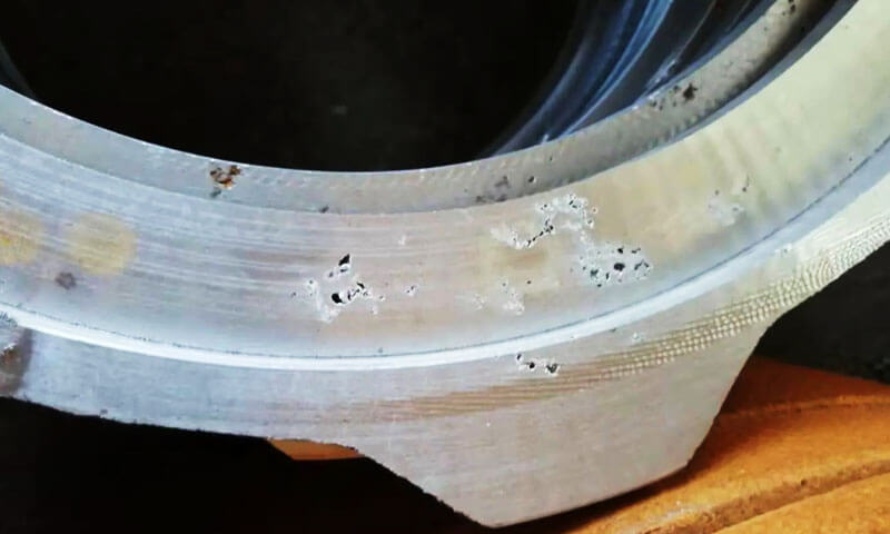
I have sat in more quality review meetings about machined die castings than I care to count, and the conversation almost always starts the same way.
The machining supervisor brings a part to the table, points at a black spot or a small cavity on a freshly milled surface, і каже: “The casting is bad. The CNC is cutting into porosity.”
And he is right—but only half right. The CNC did not create the defect. It simply revealed what was already inside the casting.
The machining operation removed the dense outer skin and exposed the subsurface porosity or slag that had been hiding there since the die casting shot.
That distinction is not academic. It determines where you spend your money. A company that tries to solve this problem at the CNC machine will spend months adjusting speeds and feeds and machining allowances and will never eliminate the defect.
A company that understands that roughly 95% of these defects originate in the die casting process will fix the problem at the source.
1. Why Porosity and Slag Defects Appear During CNC Machining
One of the most frustrating quality problems in Алюмінієвий лиття is discovering porosity or slag inclusions only after Обробка з ЧПУ.
A die-cast component may look dense and acceptable in its as-cast condition, yet milling, свердління, or boring can expose hidden defects beneath the surface.
What initially appears to be a sound casting can suddenly develop black spots, small cavities, irregular pits, or hard foreign-material inclusions.
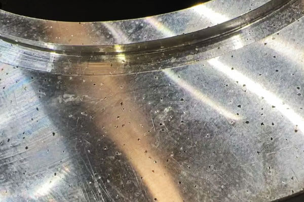
These defects are more than cosmetic issues. Depending on their location and severity, вони можуть викликати:
- Витік: Porosity exposed on sealing surfaces or internal walls can lead to air, нафта, or liquid leakage, making the component unsuitable for pressure-tight applications.
- Дефекти поверхні: Gas pores and inclusions appear as black spots, порожнини, or uneven depressions after machining.
- Tool damage: Hard oxide films and slag inclusions can accelerate tool wear, cause edge chipping, and reduce machining stability.
- Dimensional and quality problems: Defects discovered during finishing may force additional inspection, переробляти, sorting, or complete part rejection.
- Вищі витрати на виробництво: When defects are detected late in the process, the material and machining costs already invested in the component are lost.
From a die-casting and CNC machining engineering perspective, the first step is to identify the actual defect rather than immediately changing cutting parameters.
Газовий пористість, усадка пористість, and slag inclusions have different formation mechanisms and require different corrective actions.
2. How to Identify Porosity and Slag Inclusions
Before investigating the production process, distinguish between gas porosity, усадка пористість, і неметалічні включення.
Their appearance after machining provides useful clues, although visual inspection alone cannot always establish the defect type.
Газовий пористість
Gas porosity forms when gas becomes trapped in molten metal during filling or solidification.
При литтях на високий тиск, air trapped in the cavity, gas generated by excessive release agent, and other process-related gases can become enclosed as the metal solidifies.
Типові характеристики включають:
- Round or oval cavities.
- Relatively smooth internal pore walls.
- Distributed pores or localized clusters, depending on the filling and venting conditions.
- Small black spots or open cavities appearing after milling or drilling.
Gas pores are particularly problematic when they intersect machined sealing faces, різьбові отвори, рідинні проходи, or pressure-containing walls.
Усадка пористість
Shrinkage porosity forms when the metal cannot receive sufficient liquid feed to compensate for volumetric contraction during solidification.
It commonly occurs in thick sections, термічні гарячі точки, and areas where the solidification sequence prevents effective feeding.
Unlike typical gas pores, shrinkage cavities tend to have irregular shapes and rough, sometimes dendritic internal surfaces. They may appear as clustered voids or larger cavities in thick sections.
This distinction matters because increasing degassing effectiveness alone will not solve shrinkage porosity.
The solution must address local solidification, pressure transmission, температура матриці, Геометрія частини, and feeding conditions.
Slag and Oxide Inclusions
Slag inclusions are foreign materials trapped inside the casting. In aluminum die casting, these defects are often associated with oxide films, шматочок, вогнетривкі частинки, забруднені зарядні матеріали, or other non-metallic residues.
Типові характеристики включають:
- Irregular cavities or discontinuous defects.
- Чорний, сірий, or dark-colored material inside the exposed area.
- Hard particles or brittle inclusions that may damage cutting edges.
- Localized surface defects that do not necessarily have the smooth, rounded appearance of gas pores.
Oxide films can also fold into the melt during turbulent handling and filling. These films may remain embedded in the casting and become visible only after machining.
3. Root Causes of Porosity and Slag in Aluminum Die Castings
Most porosity and inclusion problems originate during melting, metal handling, начинка, або затвердіння. CNC machining is usually the detection stage rather than the source.
A useful root-cause investigation should cover four areas: якість розплаву, die-casting process, Конструкція компонентів, і стратегія обробки.
Melting and Raw Material Management
Melt quality is a major factor in controlling oxide inclusions and gas-related defects.
Poor charge management can introduce contaminants before the metal even enters the die-casting machine.
Поширені причини включають:
Excessive or contaminated recycled material
Returns and recycled aluminum can contain oil, волога, іржавий, малювати, покриття, and accumulated oxide films. Repeated remelting increases the opportunity for oxidation and contamination.
If dirty returns are charged without proper preparation, non-metallic residues can enter the melt.
Inadequate degassing and melt cleaning
Molten aluminum can absorb hydrogen, which may form gas porosity during solidification.
If degassing is insufficient, the hydrogen content may remain too high. Incomplete skimming and poor melt cleaning can also leave oxide films and dross in the liquid metal.
Poor refining-agent control
Incorrect refining-agent selection, insufficient treatment time, or inadequate process control can reduce the effectiveness of melt cleaning.
Після лікування, insufficient settling time may also allow suspended inclusions to remain in the metal being transferred.
Mixed alloy grades
Charging different aluminum alloy grades together without proper segregation can alter the chemical composition and cause the melt to fall outside the required specification.
Alloy mixing may also introduce contaminants that cannot be corrected simply through CNC machining or ordinary degassing.
З цієї причини, charge traceability, recycled-material inspection, melt treatment records, and chemical composition verification should be part of routine die-casting quality control.
Die Design and Die-Casting Process Parameters
Gas porosity is strongly influenced by cavity filling and venting. При литтях на високий тиск, molten aluminum enters the cavity at high speed.
If the filling pattern is unstable or air cannot escape effectively, gas may become trapped inside the casting.
The main contributing factors include:
| Process Factor | How It Causes Defects | Рекомендований контроль |
| Poor gate and runner design | Unstable metal flow creates turbulence and air entrapment | Optimize gate location, runner geometry, and filling sequence |
| Insufficient venting | Air and process gases remain trapped in the cavity | Inspect and clean vents, overflow channels, and vent inserts |
| Incorrect slow-to-fast shot transition | Premature high-speed filling can cause turbulence and oxide-film folding | Optimize the shot profile and transition position through trials |
| Excessive release agent | Water and volatile components generate gas during contact with the hot die | Apply a thin, uniform spray and control concentration and application volume |
Excessive plunger lubricant |
Excess lubricant can decompose and generate gas or carbonaceous residues | Control lubricant dosage and application consistency |
| Insufficient intensification | Pressure may not adequately compensate for solidification shrinkage | Verify intensification pressure, timing, and pressure transmission |
| Blocked vents or accumulated deposits | Venting efficiency decreases over successive production cycles | Establish regular cleaning and maintenance intervals |
One point deserves particular attention: the slow-to-fast shot transition. If high-speed injection begins too early, the advancing metal front may become unstable, creating turbulence and entraining air or oxide films.
If the transition occurs too late, the cavity may not fill properly. The correct setting depends on the casting geometry, сплав, машина, і дизайн матриці; it should be established through filling analysis and production trials rather than applying a universal position.
Intensification pressure also needs to be evaluated correctly. Increasing pressure indiscriminately does not eliminate gas already trapped in the cavity.
It is primarily used to improve metal feeding and reduce shrinkage-related defects where pressure can be transmitted effectively.
Product Design and Wall-Thickness Distribution
Component geometry has a direct influence on porosity formation. Large differences in wall thickness create uneven cooling rates and localized hot spots.
Thick sections tend to remain liquid longer than thin sections. If the surrounding metal solidifies first and restricts feeding, shrinkage cavities can develop in the thicker region.
Other design-related risks include:
- Abrupt wall-thickness transitions: Sudden changes in section thickness can create uneven solidification and localized shrinkage.
- Excessively thick bosses: Concentrated thermal mass increases the risk of shrinkage porosity.
- Dense rib structures: Closely spaced ribs can complicate metal flow and make venting more difficult.
- Enclosed or poorly vented cavities: Trapped air becomes harder to evacuate during filling.
Де це можливо, designers should use more uniform wall thicknesses, smoother transitions, and appropriate rib geometry.
Ворота, overflow, and vent locations should also be considered during die design, especially for components with critical machined surfaces or pressure-tight requirements.
Обробка ЧПУ: Why Defects Become Visible
CNC machining is often where hidden casting defects become apparent. The as-cast surface may remain intact even when pores or inclusions exist just below the surface.
Once the machining tool removes the outer layer, these defects are exposed.
Several machining-related factors influence the probability and severity of defect exposure.
Excessive machining allowance
If the machining allowance is unnecessarily large, the cutting tool may penetrate deeper into the casting and expose subsurface porosity.
This does not mean that reducing the allowance will eliminate the defect; it only changes how much material is removed and which internal regions become exposed.
Large cutting depth during roughing
Heavy roughing cuts can expose existing pores and may cause weak material surrounding a near-surface cavity to break away.
This can make the defect appear larger or more irregular. Однак, cutting depth is not the original cause of the internal porosity.
Severely defective incoming castings
When the casting contains extensive subsurface porosity or inclusions, even a normal machining operation can reveal defects. У таких випадках, changing spindle speed or feed rate will not solve the underlying problem.
Hard oxide and slag particles
Non-metallic inclusions may be harder or more abrasive than the surrounding aluminum matrix.
When the tool encounters these particles, cutting edges can chip or wear prematurely, affecting surface quality and tool life.
The machining team should therefore work with the die-casting supplier to establish realistic machining allowances, define critical machining zones, and assess casting quality before production begins.
4. How to Eliminate Porosity and Slag: Die-Casting Process Improvements
The most effective way to control porosity and slag is to address the defects at their source—the die-casting process.
Improvements should focus on three areas: якість розплаву, параметри впорскування, and die design with an effective venting system.
Improve Melting and Raw Material Management
Melt cleanliness directly affects the formation of oxide inclusions and gas-related defects.
Poorly managed recycled aluminum, недостатня дегазація, and incomplete slag removal can introduce contaminants into the casting.
Key control measures include:
- Control recycled material: Keep the proportion of returns at ≤30% as a process-control target, subject to alloy and material-quality requirements.
Oily, мокрий, or rusty scrap should be properly prepared, попередньо розігрітий, and dried before charging. - Strengthen melt degassing: Use rotary degassing with argon or nitrogen for sufficient treatment time to reduce dissolved hydrogen in the molten aluminum.
- Monitor melt gas content: Perform regular Reduced Pressure Tests (RPT) to evaluate melt quality and verify degassing effectiveness.
- Improve slag removal: Thoroughly skim the molten aluminum before transferring it to the die-casting machine. After refining, allow sufficient settling time so that inclusions can rise and separate.
- Install ceramic filters: Where the gating system permits, use ceramic filter elements in the runner or metal-transfer system to capture oxide films and non-metallic inclusions before they enter the cavity.
Optimize Die-Casting Parameters
Incorrect injection settings can cause turbulent filling, повітряне захоплення, and unstable metal flow. Intensification pressure and timing also affect shrinkage in thicker sections.
The following parameters should be reviewed:
- Delay the high-speed switch point: Optimize the transition from slow to fast injection to prevent premature high-speed metal flow and excessive turbulence.
- Control high-speed filling velocity: Adjust the fast-shot speed to reduce vortex formation and air entrainment while maintaining complete cavity filling.
- Optimize intensification: Increase intensification pressure where necessary and shorten excessive intensification delay to improve feeding in heavy sections and reduce shrinkage porosity.
- Control die release agent: Reduce excessive application and maintain thin, уніформа, atomized spraying. Too much release agent, particularly when it contains excess moisture, can generate gas inside the cavity.
- Reduce plunger lubricant: Use only the required amount to avoid excessive lubricant entering the shot sleeve and contributing to gas generation or black residues.
Process adjustments should be validated through controlled production trials.
Increasing injection speed or intensification pressure indiscriminately may introduce other defects, so each parameter must be evaluated against the actual casting geometry and filling behavior.
Improve Die Design and Venting
Even with clean molten aluminum and stable injection parameters, inadequate venting can leave air trapped inside the cavity. Die maintenance and gating-system optimization are therefore essential.
- Maintain venting channels: Clean vents and vent plugs on a scheduled basis to remove aluminum buildup and carbon deposits.
Blocked or damaged vents should be repaired or replaced to restore effective gas evacuation. - Optimize overflow design: Enlarge existing overflows or add new ones where necessary to collect cold metal, oxide residues, та інші забруднення.
Position them to direct unwanted material toward the biscuit and overflow areas that will be removed during trimming. - Improve runner geometry: Adjust runner and gate design to avoid direct metal impact, abrupt flow changes, and excessive turbulence during cavity filling.
- Evaluate vacuum die casting: For high-integrity components with strict airtightness or leak-tightness requirements, consider vacuum-assisted die casting.
By reducing the amount of air trapped in the cavity, it can substantially lower gas porosity and improve internal casting quality.
Engineering priority: Start with melt quality and process-parameter control, then address venting and gating problems.
For demanding pressure-tight components, vacuum die casting can provide an additional level of process control.
5. CNC Machining Strategies to Reduce Defect Exposure and Scrap
When die-casting improvements cannot be implemented immediately, the CNC process can help contain quality losses.
The objective is to avoid unnecessary material removal, identify defective blanks early, and prevent defective components from consuming the full machining cycle.
It is important to set the right expectation: these measures reduce defect exposure and downstream scrap; they do not eliminate internal casting defects.
Optimize Machining Allowance
Review the machining allowance for each critical surface. Where the drawing and functional requirements permit, avoid unnecessarily large stock removal that penetrates deeper into the casting than required.
Наприклад, if a die-cast valve body or pump housing has a critical sealing face, the machining allowance should be agreed upon by the design, штамп, and CNC teams.
Reducing the allowance without confirming casting dimensions and surface condition may create other problems, such as insufficient cleanup, dimensional nonconformance, or residual as-cast skin.
The correct approach is to establish an allowance that reliably removes the required surface layer while minimizing unnecessary penetration into the casting.
Use a Staged Machining Sequence
Avoid removing excessive material in one heavy cut, particularly when machining zones are known to contain near-surface porosity.
A more controlled sequence is:
- Груба обробка: Remove the main machining allowance while monitoring exposed defects and tool behavior.
- Intermediate inspection: Check critical surfaces after roughing, before investing time in finishing operations.
- Semi-finishing and finishing: Continue only when the component meets the agreed acceptance criteria.
For high-risk components, introduce an inspection gate after rough machining.
Parts with unacceptable porosity or inclusions can then be rejected before finishing, свердління, різьблення, or other value-added operations.
This approach is especially useful for complex housings, Тіла клапана, компоненти насосів, and other castings with multiple machining operations.
Inspect Incoming Castings Before CNC Processing
Incoming inspection is one of the most effective ways to prevent defective blanks from entering expensive machining cycles.
Depending on component geometry and quality requirements, inspection methods may include:
- Візуальний огляд: Identify surface cracks, Холод закривається, exposed pores, and obvious casting defects.
- Рентгенологічна рентгенографія: Detect internal porosity and inclusions in suitable sections of the casting.
- Computed tomography (КТ): Provide more detailed three-dimensional information about internal defects, particularly for complex or high-value components.
- Sectioning and metallographic examination: Verify defect type, розмір, розподіл, and location through destructive sampling.
Наприклад, when a batch of aluminum die-cast housings repeatedly develops pores around machined mounting holes, X-ray inspection or targeted sectioning can help determine whether the defects are already present in the incoming blanks.
If the defect rate is excessive, the batch should be held for evaluation rather than sent directly into full CNC production.
Inspection frequency should be based on casting risk, supplier performance, batch history, and customer requirements.
Radiographic inspection is not automatically necessary for every component, but it is valuable when internal integrity directly affects product function.
Select Tools for Machining Aluminum with Inclusions
Aluminum is generally easy to machine, but oxide films and hard non-metallic inclusions can create localized tool damage.
When the cutting edge encounters these particles, it may experience accelerated abrasion, micro-chipping, or unstable cutting forces.
Use suitable carbide tooling with an appropriate wear-resistant grade and cutting-edge geometry.
Tool selection should also consider aluminum adhesion, відкачування стружки, Швидкість різання, швидкість подачі, and coolant strategy.
If tool damage repeatedly occurs at the same machining location, do not assume that the cutting parameters are the only problem.
Inspect the machined surface and, де це можливо, examine the casting cross-section for hard inclusions.
6. Перевірка та контроль якості: Closing the Loop Between Casting and CNC
A reliable solution requires more than correcting individual defects. The die-casting and CNC teams need a shared inspection and traceability system so that machining results can be used to improve the upstream process.
Inspect the First Machined Part Carefully
The first machined component should receive a thorough visual inspection, especially around:
- Sealing faces and gasket contact surfaces.
- Drilled and tapped holes.
- Thin walls and locally thick sections.
- Fluid passages and pressure-containing areas.
- Mounting faces and other critical functional surfaces.
Pay particular attention to small black spots, open cavities, irregular pits, and exposed inclusions. A defect that appears minor on a non-functional surface may be unacceptable on a sealing face.
Use Sectioning to Identify the Actual Defect
When porosity or slag appears during production, select representative defective components for cross-section analysis.
Examine the defect’s shape, internal surface, location, and surrounding material.
This helps distinguish gas porosity from shrinkage cavities and non-metallic inclusions.
The findings should be communicated to the die-casting team with the exact component location and machining depth at which the defect appeared.
Наприклад, if defects repeatedly appear near the end of the metal-filling path, the investigation should focus on filling behavior, вентиляція, and overflow effectiveness.
If irregular shrinkage cavities concentrate around thick bosses, local solidification and intensification conditions deserve closer attention.
Establish Defect Mapping and Batch Traceability
Do not record defects simply as “porosity” or “black spots”. Record where they occur, how frequently they appear, and which production batches are affected.
A useful defect record should include:
| Information | Мета |
| Component number and casting batch | Identify affected production lots |
| Machined surface and defect location | Determine whether defects concentrate in specific regions |
| Machining depth and allowance | Establish how much material was removed before exposure |
| Defect appearance and dimensions | Support classification and severity assessment |
| Die-casting machine and process parameters | Identify possible process-related patterns |
| Melt batch and material records | Investigate contamination and melt-quality variation |
| CNC machine, інструмент, and shift | Check whether defects correlate with machining conditions |
This information helps distinguish an isolated material problem from a recurring process issue. Що важливіше, it provides evidence for corrective actions instead of relying on assumptions.
7. Practical Troubleshooting: A Step-by-Step Validation Process
When a machined aluminum casting develops porosity or slag, a structured investigation is more effective than changing machine settings at random.
Крок 1: Section the defective component
Cut through a representative defect and examine its morphology. Identify whether it is likely to be gas porosity, усадка пористість, or a non-metallic inclusion.
Крок 2: Check the defect location
Compare the defect position with the casting geometry, gate and overflow layout, thick-wall regions, and CNC machining depth.
Крок 3: Review melt quality and shot parameters
Check charge-material condition, degassing records, чистота розплаву, shot transition position, release-agent application, and intensification settings.
Крок 4: Run a controlled production trial
Adjust selected parameters and produce a trial batch. Keep other important conditions stable so that the effect of each change can be evaluated.
Крок 5: Inspect the machined results
Compare defect frequency and distribution after CNC machining, not just the visual condition of the as-cast parts.
Крок 6: Modify the die or evaluate vacuum assistance if necessary
If parameter and melt-quality improvements are insufficient, investigate venting, overflow, and gating modifications. For demanding airtightness applications, evaluate vacuum die casting.
The key is to verify improvements using machined-part results. A casting that looks better before machining is not necessarily free from subsurface defects.
8. Common Mistakes When Dealing with Die-Casting Porosity and Slag
Several troubleshooting approaches may appear reasonable but often fail to address the actual cause.
Mistake 1: Changing Only CNC Speed and Feed
Adjusting spindle speed, швидкість подачі, or cutting depth can influence surface finish, знос інструменту, and the way an existing defect is exposed.
Однак, these changes cannot remove gas pores or oxide inclusions already embedded in the casting.
If defects repeatedly appear in the same regions, investigate the casting process rather than relying on CNC parameter adjustments.
Mistake 2: Increasing Machining Allowance to Remove All Porosity
Adding more machining allowance does not guarantee that pores will disappear.
Subsurface porosity may extend deeper into the component, and removing more material can expose additional cavities or compromise the required wall thickness.
Machining allowance should be determined by casting capability, drawing requirements, and the location of critical functional surfaces—not by repeatedly increasing stock removal to chase internal defects.
Mistake 3: Ignoring Recycled-Material Quality
Using large quantities of poorly controlled recycled aluminum can introduce oil, волога, оксид фільмів, and other contaminants into the melt.
If charge-material management remains unchanged, slag-related defects may continue to recur even after adjustments to CNC operations.
Recycled material should be managed through alloy segregation, вимоги до чистоти, preparation procedures, and melt-quality verification.
Mistake 4: Treating All Internal Cavities as Gas Porosity
Газовий пористість, усадка пористість, and inclusions have different causes. Applying the same corrective action to all three wastes production time.
Наприклад, better degassing may reduce hydrogen-related gas porosity, but it will not correct a poorly fed thick section.
Аналогічно, improving venting will not remove oxide inclusions already present in the melt.
Correct classification must come before process adjustment.
9. Short-Term Containment vs. Long-Term Defect Prevention
Not every die-casting operation can immediately modify its tooling or install vacuum equipment.
A practical improvement plan should separate immediate containment from permanent corrective action.
| Improvement Stage | Recommended Actions | Основна мета |
| Short-term containment | Reduce unnecessary machining allowance where approved, inspect incoming blanks, and introduce rough-machining inspection | Prevent defective castings from consuming the full CNC cycle |
| Medium-term improvement | Strengthen degassing and slag removal, optimize shot transition and release-agent application, clean vents and overflows | Reduce gas porosity and inclusion defects at the casting stage |
| Long-term prevention | Improve gating and overflow design, implement vacuum die casting where justified, and establish strict charge-material controls | Improve internal casting integrity and production consistency |
Наприклад, a manufacturer producing aluminum valve bodies may initially introduce X-ray sampling and an inspection gate after rough machining to reduce leakage-related scrap.
In parallel, the die-casting team can optimize melt treatment and venting.
If the required airtightness level still cannot be achieved consistently, the manufacturer may need to redesign the gating and overflow system or evaluate vacuum-assisted die casting.
This layered approach controls immediate losses while addressing the root cause.
10. How to Build a More Reliable Die Casting and CNC Machining Process
Porosity and slag defects cannot be controlled effectively when die casting and CNC machining operate as isolated processes.
The casting supplier may focus on filling and solidification, while the machining team focuses on dimensions and surface finish. Yet the quality of the final machined component depends on both.
A more reliable manufacturing process should establish shared controls:
- At the design stage: Identify critical machined surfaces, sealing areas, pressure-containing walls, and acceptable internal defect limits.
- During die casting: Control melt cleanliness, hydrogen content, стабільність наповнення, вентиляція, інтенсифікація, and die maintenance.
- Before machining: Verify incoming casting quality according to component risk and customer requirements.
- Під час обробки ЧПУ: Use validated machining allowances, controlled cutting sequences, and intermediate inspection for high-risk features.
- Після обробки: Inspect critical surfaces and functional features, including pressure or leak testing where required.
- For continuous improvement: Feed defect-location data and machining inspection results back to the die-casting process.
The acceptance criteria should also distinguish between different applications. A cosmetic housing, a structural bracket, and a pressure-tight valve body do not have the same tolerance for internal porosity.
Defect limits should be defined according to function, геометрія компонентів, applicable standards, and customer requirements.
11. Висновок
Porosity and slag exposed during CNC machining are usually symptoms of problems originating in aluminum melting, metal handling, начинка, вентиляція, або затвердіння.
CNC machining makes these defects visible, but changing cutting parameters alone cannot eliminate their root causes.
Для виробників, the most effective strategy is to improve melt cleanliness, control gas content, optimize injection parameters, maintain venting systems, and review gating and overflow design.
CNC-side measures—including optimized machining allowances, staged material removal, incoming inspection, and suitable tooling—help reduce scrap and prevent defective parts from progressing through the production line.
The most reliable results come from integrating die casting and CNC machining into one quality-control system.
В Промисловість, controlling casting quality and machining performance together is essential to producing precision aluminum components with consistent dimensions, надійні ущільнювальні поверхні, and dependable service performance.
Поширені запитання
How do I distinguish porosity from slag?
Section the defective part. Porosity cavities are round or oval with smooth internal walls.
Slag cavities are irregular and contain black or gray oxide or slag material. Slag also causes tool chipping and accelerated wear.
What causes gas porosity in die castings?
Gas porosity is caused by trapped cavity gas, early high-speed switchover, excessive fill speed, excessive die release agent or plunger oil, and blocked vents. Insufficient intensification pressure can cause shrinkage porosity in heavy sections.
Will increasing the machining allowance remove the porosity?
Ні. Increasing the allowance usually makes it worse, because a deeper cut reaches deeper into the casting where porosity is more likely. More cavities are exposed and the scrap rate rises.
What is the most effective single measure for leak-critical castings?
Vacuum die casting. It substantially reduces gas porosity and is the preferred approach for high-integrity, leak-critical parts.

