

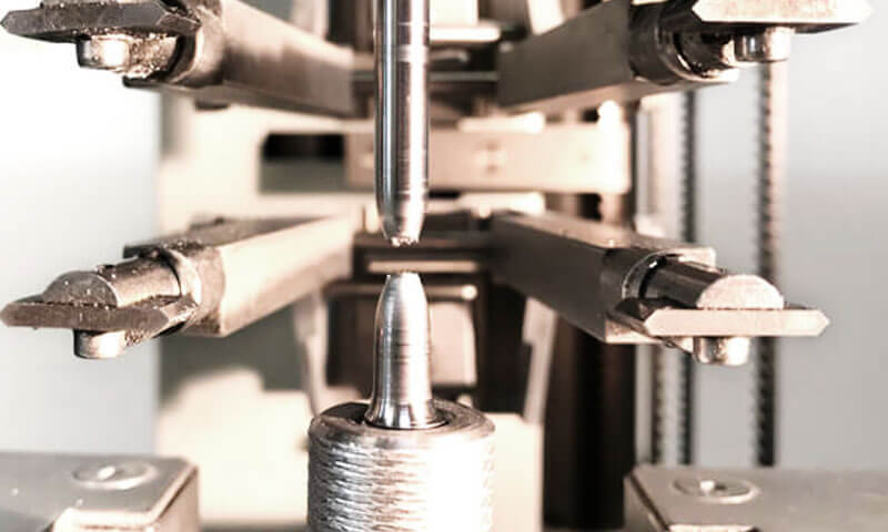
In the field of materials engineering and structural design, few concepts are as fundamental—and as frequently misunderstood—as tensile strength and yield ikaika.
These two mechanical properties are the cornerstones of material selection, structural analysis, and failure prediction.
Eia naʻe, lawehala, Manaʻoʻia, and students often struggle to articulate the distinction between them and, more importantly, which one governs material failure in real-world applications.
The short answer is: both matter, but for different reasons and in different contexts.
Yield strength determines when a material begins to deform permanently, while tensile strength determines when it ultimately breaks.
The failure mode—whether by excessive deformation or catastrophic fracture—depends on the material, the application, and the design philosophy.
Hāʻawi kēiaʻatikala i kahi paʻa, rigorous examination of tensile strength and yield strength.
1. Understanding the Stress-Strain Relationship: The Foundation of Material Failure Analysis
Before comparing ka ikaika and ikaika ikaika, it is essential to understand the fundamental relationship between stress and strain.
'Ōlelo stress-strain curve is one of the most important tools in mechanical engineering and materials science because it provides a complete picture of how a material responds when subjected to an external load.
Almost every engineering material undergoes some form of deformation when a force is applied.
The way a material deforms—whether it returns to its original shape, permanently changes shape, or fractures completely—depends on its internal structure, Ka Hoʻolālā, hana hana hana, and loading conditions.
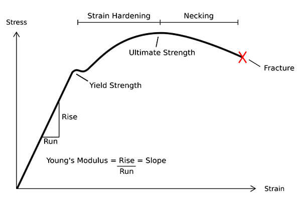
The Engineering Stress-Strain Curve
The stress-strain curve is obtained by subjecting a standardised test specimen to a steadily increasing tensile load while measuring the resulting elongation.
The curve is divided into distinct regions, each corresponding to a specific mechanical behaviour.
| Kahuna | Nāʻano hana | Engineering Significance |
| Elastic Region | The material deforms temporarily and returns to its original shape after the load is removed. | Stress is proportional to strain according to Hooke’s Law. The material remains undamaged. |
| Proportional Limit | The highest stress point where stress and strain maintain a linear relationship. | Defines the boundary of ideal elastic behavior. |
| Yield Region | The material begins to transition from elastic deformation to permanent plastic deformation. | Yield strength is determined at this stage and represents the beginning of permanent deformation. |
| Plastic Region | The material undergoes irreversible deformation and does not return to its original shape. | Plastic deformation occurs; strain hardening increases material resistance. |
ʻO ka ikaika hope loa (Us) |
The material reaches its maximum load-carrying capacity. | Tensile strength is defined at this point. |
| Necking Region | Localized reduction in cross-sectional area occurs after UTS. | The specimen weakens locally before fracture. |
| Fracture Region | The material separates completely. | Represents final mechanical failure. |
Key Points on the Stress-Strain Curve
The major mechanical properties obtained from the stress-strain curve are summarized below:
| ʻIke Kūlana | Hōʻailona | ʻO wehewehe | Engineering Significance |
| Proportional Limit | σPL | Maximum stress where stress remains directly proportional to strain. | Defines the limit of linear elastic behavior. |
| Elastic Limit | σEL | Maximum stress before permanent deformation begins. | Indicates the boundary between recoverable and permanent deformation. |
Ka ikaika |
σY | Stress at which plastic deformation starts. | Determines the allowable design stress for many engineering components. |
| ʻO ka ikaika hope loa | σUTS | Maximum stress the material can withstand during tensile loading. | Indicates maximum load capacity before necking begins. |
| Fracture Strength | σF | Stress level at which the material breaks. | Represents final material failure. |
2. What Is Yield Strength?
Yield strength is one of the most important mechanical properties used to evaluate the load-bearing capability and reliability of engineering materials.
It defines the stress level at which a material changes from elastic deformation, where it can recover its original shape after unloading, i hoʻoheheʻe plastic, where permanent deformation occurs.
In engineering practice, yield strength is often considered the primary design limit because many components are considered to have failed once they experience unacceptable permanent deformation, even if they have not fractured.
ʻo kahi laʻana, a steel support structure that bends permanently under load, a valve component that loses dimensional accuracy, or a pressure vessel that deforms beyond its allowable limit may still remain physically intact, but these conditions can significantly affect safety and performance.
No laila, yield strength is not simply a measure of material strength—it represents the boundary between acceptable operation and irreversible mechanical damage.
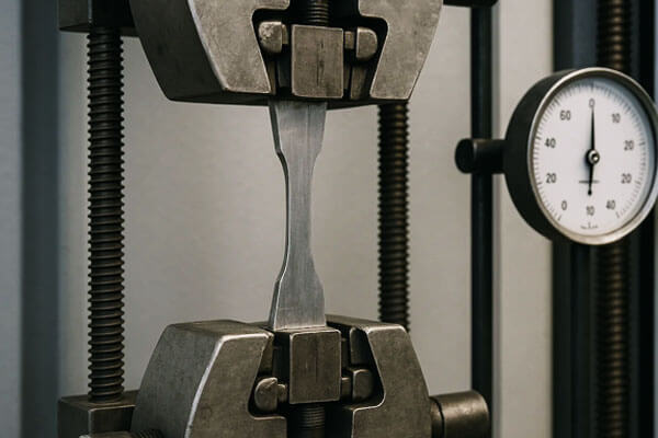
Definition and Physical Meaning of Yield Strength
Ka ikaika (σY) is defined as the stress at which a material begins to undergo permanent plastic deformation.
Before reaching the yield point, the relationship between stress and strain remains approximately linear.
The material follows elastic behavior, meaning that once the external load is removed, the atoms return to their original positions and the component recovers its initial shape.
Akā naʻe,, when the applied stress exceeds the yield strength, irreversible changes occur within the material structure.
Dislocations inside the crystal lattice begin to move, atomic layers slide relative to each other, and permanent deformation develops.
The behavior can be summarized as:
Elastic deformation → Yielding → Plastic deformation → Failure
The engineering stress applied to a material is calculated as:
σ=F/A₀
IA MEA:
- a = engineering stress (Mpa)
- F = applied tensile force (N)
- A₀ = original cross-sectional area (mm²)
The yield strength corresponds to the stress value where the material begins to deviate from purely elastic behavior.
Why Yield Strength Is Critical in Engineering Design
Although tensile strength represents the maximum stress a material can withstand before fracture, yield strength is usually more important for components that must maintain their shape and dimensional stability during service.
A component may not need to break to be considered failed. In many applications, permanent deformation itself represents a functional failure.
ʻo kahi laʻana, in mechanical systems:
- A shaft that permanently bends may create misalignment and excessive vibration.
- A valve component that deforms may lose sealing performance.
- A precision-machined part that yields may no longer meet dimensional requirements.
- A structural member that plastically deforms may lose its designed load distribution capability.
No laila, engineers typically design operating stresses below the yield strength using an appropriate safety factor.
ʻo kahi laʻana, if a material has a yield strength of 500 MPa and the selected safety factor is 2, the maximum recommended design stress would be approximately 250 Mpa.
How Yield Strength Is Determined
The method used to measure yield strength depends on the deformation characteristics of the material. Some materials exhibit a clear yield point, while others transition gradually from elastic to plastic behavior.
A tensile test is the standard method used to determine yield strength.
During testing, a standardized specimen is subjected to an increasing tensile load while the corresponding elongation is continuously measured.
The resulting stress-strain curve provides information about the material’s mechanical behavior.
The measurement method varies according to material type.
| ʻAnoʻano | Kūlana | ʻO ka weheweheʻana |
| Materials with a distinct yield point (E.g., ʻO kaʻaihueʻoluʻolu) | Direct measurement from the stress-strain curve. | Yield strength is the stress at the first point of deviation from linearity (the yield point). |
| Materials without a distinct yield point (E.g., aluminum, keleawe) | 0.2% offset method | A line parallel to the elastic slope is drawn at 0.2% kū; the intersection with the stress-strain curve defines the yield strength. |
| Materials with a yield plateau (E.g., Kekuhi Kahule haʻahaʻa) | Upper and lower yield points. | The upper yield point is the peak before the plateau; the lower yield point is the plateau value. |
'Ōlelo 0.2% Offset Yield Strength Method
Many engineering metals do not show a clearly defined yield point. ', they gradually transition from elastic deformation to plastic deformation.
Typical examples include:
- Apana Apana Aluminum
- Nā pāpale keleawe
- Nā Alloys Annays Alloys
- High-strength stainless steels
For these materials, engineers commonly use the 0.2% offset yield strength method, kaulana loa e like me ka 0.2% proof stress method.
The procedure involves:
- Identifying the linear elastic portion of the stress-strain curve.
- Drawing a line parallel to the elastic slope.
- Shifting this line by a strain value of 0.002 (0.2% permanent strain).
- Determining the intersection point between the offset line and the stress-strain curve.
The stress value at this intersection is defined as the yield strength.
This method provides a consistent engineering standard because it avoids uncertainty in materials where the transition into plastic deformation is gradual.
Typical Yield Strength Values of Common Engineering Materials
Yield strength varies significantly depending on alloy composition, ʻO ka hana wela, hana hana hana, and material condition.
The following values represent typical room-temperature yield strengths for commonly used engineering materials.
| Waiwai | Typical Yield Strength (Mpa) | Nāʻano hiʻohiʻona |
| AISI 1018 Kekuhi Kahule haʻahaʻa | 220-370 | Widely used structural steel with good ductility and weldability |
| AISI 1045 Ke kila kiladi | 310-450 | ʻOi nui ka ikaika; heat-treated conditions provide improved performance |
| Kila kohu ʻole 304 (Anned) | 205-310 | Austenitic stainless steel with excellent corrosion resistance |
| 17-4PH Stainless steel H900 | 1,170-1,200 | Precipitation-hardening stainless steel with very high strength |
Alumini 6061-T6 |
240-260 | General-purpose heat-treated aluminum alloy |
| Aluminim 7075-t6 | 460-500 | High-strength aerospace aluminum alloy |
| Brass C36000 | 240-340 | Excellent machinability with moderate strength |
| Annealed copper | 55-70 | Highly ductile but relatively low strength |
| ʻO ka papa Titanium 5 (Ti-6al-4v) | 830-880 | Aerospace alloy with excellent strength-to-weight ratio |
| 'Āpana hina | Not clearly defined | Brittle material with limited plastic deformation |
3. What Is Tensile Strength?
Tensile strength is one of the most widely used mechanical properties for evaluating a material’s ability to withstand pulling forces before failure.
It represents the maximum tensile stress that a material can sustain before necking begins and the load-carrying capability starts to decrease.
Unlike yield strength, which defines the beginning of permanent deformation, tensile strength describes the ultimate strength limit of a material under tensile loading.
It provides valuable information about the material’s resistance to fracture, its load-bearing capacity, and its overall mechanical performance.
In engineering applications, tensile strength is particularly important for components subjected to high tensile forces, e like me nā mea pāʻani, Kāleʻa, nā'āpana ikaika, Nā lālā hoʻonohonoho, and load-bearing mechanical parts.
Akā naʻe,, tensile strength alone does not determine whether a material is suitable for a specific application.
A complete material evaluation must also consider yield strength, kumaikalua, paʻakikī, ʻO ka paleʻana o ka momona, a me nā kūlana kūlohelohe.
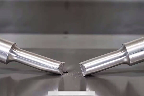
Definition of Tensile Strength
Ikaika ikaika, i kapaia ia e like me ʻO ka ikaika hope loa (Us), is defined as the maximum engineering stress a material can withstand during a tensile test before the onset of localized deformation and eventual fracture.
It is represented as:
σUTS=F_max/A₀
IA MEA:
- σUTS = ultimate tensile strength (MPa or psi)
- F_max = maximum load applied (N or lb)
- A₀ = original cross-sectional area (mm² or in²)
Nā mea nui:
- The tensile strength is calculated using the original cross-sectional area, not the reduced area after necking.
- The true stress at fracture (which accounts for the reduced area) is higher than the engineering tensile strength.
- Tensile strength is a measure of resistance to fracture, not resistance to deformation.
Physical Meaning of Tensile Strength
From a material science perspective, tensile strength represents the ability of a material’s internal structure to resist separation under an applied tensile force.
When a tensile load is applied:
- Atomic bonds resist separation.
- Elastic deformation occurs first.
- Plastic deformation begins after yielding.
- The material continues to strengthen through strain hardening.
- Maximum strength is reached at the tensile strength point.
- Further deformation causes necking and fracture.
The difference between yield strength and tensile strength reflects the material’s ability to undergo plastic deformation before failure.
No nā mea hana ducle:
σY<σUTS
The larger the difference between yield strength and tensile strength, the greater the material’s ability to deform plastically before breaking.
How Tensile Strength Is Measured
Tensile strength is determined through a standardized tensile test.
The typical testing procedure includes:
- Preparing a standardized specimen with known dimensions.
- Mounting the specimen in a universal testing machine.
- Applying a gradually increasing tensile force.
- Measuring elongation and applied load continuously.
- Calculating engineering stress and strain.
- Identifying the maximum stress point on the stress-strain curve.
Common testing standards include:
- Asthma E8 / E8M — Standard Test Methods for Tension Testing of Metallic Materials
- ISO 6892-1 — Tensile Testing of Metallic Materials
Typical Tensile Strength Values of Common Engineering Materials
Different materials exhibit significantly different tensile strength levels.
| Waiwai | ʻO ka ikaika maʻamau (Mpa) | Nāʻano hiʻohiʻona |
| Low-carbon steel AISI 1018 | 370–440 | General structural steel with good ductility |
| Medium-carbon steel AISI 1045 | 570-700 | Higher strength mechanical steel |
| Kila kohu ʻole 304 | 500-750 | Corrosion-resistant austenitic stainless steel |
| 17-4PH stainless steel H900 | 1,300-1,400 | High-strength precipitation-hardening stainless steel |
Alumini 6061-T6 |
300-320 | Lightweight structural aluminum alloy |
| Aluminim 7075-t6 | 530-570 | Aerospace-grade high-strength aluminum |
| Brass C36000 | 340-470 | Excellent machinability and moderate strength |
| Copper annealed | 200-250 | Highly conductive and ductile |
| ʻO ka papa Titanium 5 Ti-6al-4v | 900-950 | High-performance aerospace alloy |
| 'Āpana hina | 150-350 | Brittle material with limited tensile capability |
4. Key Differences Between Yield Strength and Tensile Strength
Yield strength and tensile strength are two fundamental mechanical properties used to describe how a material responds to tensile loading.
Although both are obtained from the stress-strain curve, they represent different stages of material behavior and different definitions of failure.
The essential difference is:
- Yield strength defines the point where a material begins to deform permanently.
- Ikaika ikaika (ʻO ka ikaika hope loa, Us) defines the maximum stress a material can withstand before necking and eventual fracture occur.
In engineering design, yield strength is usually associated with functional failure, while tensile strength is associated with ultimate structural failure.
A component may still be physically intact after exceeding its yield strength, but it may no longer meet dimensional, HanaPal, or safety requirements.
Comparison Between Yield Strength and Tensile Strength
| Loko | Ka ikaika | Ikaika ikaika (Us) |
| ʻO wehewehe | The stress at which permanent plastic deformation begins | The maximum stress a material can withstand before the onset of necking and fracture |
| Hōʻailona | σY | σUTS |
| Position on stress-strain curve | Located at the end of the elastic region and the beginning of plastic deformation | Represents the highest point of the engineering stress-strain curve |
| Material behavior | Indicates the transition from elastic behavior to irreversible deformation | Indicates the maximum load-carrying capability before material degradation begins |
| Koʻikoʻi ʻenekinia | Determines when a component will permanently change shape | Determines the ultimate strength limit before fracture |
Primary failure mode |
Hana kīleʻa, hoʻololi dimensional, Kauhai, morliengente | Moikaika ', ʻO ka hoʻolahaʻana, and complete fracture |
| Design philosophy | Prevent permanent deformation and maintain functional integrity | Prevent catastrophic rupture and ensure structural safety |
| Physical meaning | Resistance to the initiation of plastic flow | Resistance to complete separation under tensile loading |
| Typical measurement method | Direct yield point measurement or 0.2% offset method | Maximum applied load divided by original cross-sectional area |
| Design application | Primary design criterion for most structural and mechanical components | Important for fracture-critical and high-load applications |
| Typical safety factor basis | Commonly used for allowable stress calculations (typically 1.5–2.0 depending on application) | Used for evaluating ultimate failure conditions (often higher safety margins for critical components) |
Tensile Strength-to-Yield Strength Ratio of Different Materials
| Ikaika ikaika / Yield Strength Ratio | Nāʻano hana | Nā mea maʻamau | Nāʻano hiʻohiʻona |
| Aneane 1.0 | Brittle behavior | 'Āpana hina, Nā Kūlana, aniani | Little or no plastic deformation; failure occurs shortly after elastic limit |
| 1.5-2.0 | Ductile behavior | Kekuhi Kahule haʻahaʻa, Apana Apana Aluminum, nā mea kanu lāʻau | Significant plastic deformation before fracture; provides warning before failure |
| Greater than 2.0 | Highly ductile behavior | Annealed copper, ʻO kekahi mau polymers | Large deformation capacity; high energy absorption before fracture |
5. Which Metric Determines Material Failure?
Determining whether ka ikaika Oole ikaika ikaika controls material failure is not a simple question with a single answer.
In engineering, the definition of failure depends on the function of the component, the type of loading, the material behavior, and the consequences of damage.
A common misunderstanding is that a material “fails” only when it breaks. I loko o kaʻoiaʻiʻo, engineering failure can occur long before fracture.
A component that has permanently deformed, lost dimensional accuracy, or can no longer perform its intended function is already considered failed, even if the material remains physically continuous.
No laila, the most accurate interpretation is:
Yield strength determines the beginning of irreversible damage and functional failure, while tensile strength determines the ultimate limit before structural fracture.
For most ductile metal components, yield strength is the primary design criterion because preventing permanent deformation is usually more important than reaching the maximum possible strength of the material.
Akā naʻe,, in fracture-critical applications, tensile strength becomes a key parameter for preventing catastrophic failure.
Understanding Failure: Yielding vs Fracture
Material failure under tensile loading generally occurs through two different mechanisms: plastic deformation failure and fracture failure.
Yield Failure: When a Component Loses Its Intended Function
Yield failure occurs when the applied stress exceeds the material’s yield strength.
I kēia manawa, the material enters the plastic deformation region, meaning that it will no longer return completely to its original shape after the load is removed.
The component may continue to carry additional loads because the material has not yet reached its ultimate strength. Akā naʻe,, the permanent deformation may already make the component unsuitable for service.
ʻo kahi laʻana, consider a precision-machined shaft used in industrial equipment.
If the shaft experiences stress above its yield strength, it may permanently bend. Although it has not fractured, the deformation can cause:
- Misalignment between rotating components
- Increased vibration
- Premature bearing wear
- Reduced operational accuracy
Like me, a valve component may remain intact after yielding but lose its sealing performance because of dimensional changes.
In these situations, the component has experienced engineering failure, even though tensile strength has not been reached.
Fracture Failure: When the Material Loses Structural Integrity
Fracture failure occurs when the material reaches its ultimate tensile capacity and can no longer sustain increasing loads.
During a tensile test, the material first reaches its maximum stress value, known as the ultimate tensile strength (Us). After this point, localized deformation called necking begins.
The cross-sectional area decreases rapidly in a specific region, reducing the material’s ability to carry load.
The failure process typically involves:
- Maximum tensile stress is reached.
- Localized necking develops.
- Internal defects or cracks grow.
- The remaining cross-section becomes insufficient.
- Final fracture occurs.
In applications such as lifting cables, nā mea hana paʻa, a me nā wahi mokulele, fracture represents the most serious type of failure because it can occur suddenly and cause catastrophic consequences.
Why Yield Strength Usually Controls Engineering Design
For most structural and mechanical applications, engineers design components to operate below the yield strength rather than below tensile strength.
The reason is that permanent deformation can compromise performance even when the component retains significant residual strength.
The relationship for ductile metals is usually:
σY<σUTS
This means that a material can continue carrying additional load after yielding begins.
Akā naʻe,, allowing a component to enter the plastic region is generally unacceptable because the original design assumptions are no longer valid.
Common consequences of yielding include:
Loss of Dimensional Accuracy
Precision components often require strict dimensional control. Even small permanent deformation can affect assembly accuracy and performance.
Reduced Fatigue Life
Plastic deformation introduces residual stresses and microstructural changes that may accelerate fatigue crack initiation.
Loss of Safety Margin
Once yielding occurs, the remaining strength margin before fracture is reduced.
No kēia kumu, engineering design standards commonly use yield strength as the basis for allowable stress calculations.
When Tensile Strength Becomes the Critical Failure Criterion
Although yield strength controls many engineering designs, tensile strength becomes the dominant consideration when the primary requirement is preventing complete rupture.
This is particularly important in applications where failure could lead to immediate safety hazards.
High-Tension Components
Nā mea e like me:
- Suspension cables
- Wire ropes
- High-strength bolts
- Anchoring systems
are designed primarily to withstand large tensile forces.
For these applications, the main concern is not whether the component slightly deforms, but whether it can continue carrying the required load without breaking.
Nā kumuhana Britle
Tensile strength is also more important for brittle materials because they exhibit little or no plastic deformation before fracture.
Hoʻokomoʻia nā hiʻohiʻona:
- 'Āpana hina
- Nā Kūlana
- Aniani
Unlike ductile metals, brittle materials generally do not have a clearly defined yield point. Their stress-strain curves show an almost entirely elastic response followed by sudden fracture.
For these materials:
- Yield strength may not be meaningful.
- Tensile strength provides a better indication of failure resistance.
- Fracture toughness becomes an important additional property.
Why Strength Alone Does Not Define Failure
Although yield strength and tensile strength are fundamental mechanical properties, real-world failures often occur through other mechanisms.
Fatigue Failure
Many components fail after repeated loading cycles even when the applied stress remains below the yield strength.
Typical examples include:
- Rotating shafts
- Aircraft structures
- Na'Āpana Engine
Fatigue failure depends on:
- Stress cycles
- 'Ōlao'ōmaʻomaʻo
- Material microstructure
- ʻO nā kūlana noho
Creep Failure
I nā mahana kiʻekiʻe, materials may slowly deform under constant stress.
This is critical for:
- Nā'āpana Turbine
- Nāʻaiʻana
- High-temperature pressure equipment
I kēia mau hihia, creep strength and stress rupture properties are more important than room-temperature tensile strength.
Environmental Failure
Material performance can also be reduced by environmental conditions.
Hoʻokomoʻia nā hiʻohiʻona:
- Kuupuiawi
- Hydrogen embrittlement
- ʻO ke kūleʻaʻana o ke kalaʻana
A material with excellent tensile properties may still fail prematurely if it lacks sufficient environmental resistance.
6. Yield Strength vs Tensile Strength in Different Materials
Mea waiwai (Kukui Kekuhi, Aluminum, keleawe)
| Waiwai | Ka ikaika (Mpa) | Ikaika ikaika (Mpa) | Ratio (UTS/Yield) | ʻO keʻano hanaʻole |
| Kekuhi Kahule haʻahaʻa (1018) | 220-370 | 370-440 | 1.2-1.7 | Yielding first; then work hardening; necking; ʻoki pio. |
| Kila kohu ʻole (304) | 205-310 | 515-720 | 1.7-2.5 | Yielding; significant ductility; necking; ʻoki pio. |
| Aluminum (6061-T6) | 240-260 | 290-310 | 1.1-1.3 | Palena palena; yielding then fracture. |
| keleawe (Anned) | 55-70 | 210-240 | 3.0-4.0 | Very ductile; large plastic deformation; necking; ʻoki pio. |
Failure criterion: No nā mea hana ducle, ka ikaika typically governs serviceability (hapa), oiai ikaika ikaika governs ultimate safety (ʻoki pio). Designers must consider both.
Nā kumuhana Britle (Hae hao, Nā Kūlana, Aniani)
| Waiwai | Ka ikaika (Mpa) | Ikaika ikaika (Mpa) | Ratio (UTS/Yield) | ʻO keʻano hanaʻole |
| 'Āpana hina | No yield | 150-350 | ~ 1.0 | Fractures without significant plastic deformation. |
| Nā Kūlana (Nā Alluna) | No yield | 200-400 | ~ 1.0 | Frittle fricture; no yielding. |
| Aniani | No yield | 50-100 | ~ 1.0 | Sudden fracture; no warning. |
Failure criterion: For brittle materials, ikaika ikaika is the only meaningful metric. The material will fail by fracture shortly after the elastic limit is exceeded.
High-Strength Alloys (17-4Ph, Titanium)
| Waiwai | Ka ikaika (Mpa) | Ikaika ikaika (Mpa) | Ratio (UTS/Yield) | ʻO keʻano hanaʻole |
| Stainless steel 17-4PH | 1,170-1,200 | 1,310-1,370 | 1.1-1.2 | Limited plastic deformation; fracture occurs shortly after yielding. |
| Titanium Ti-6Al-4V | 830-880 | 900-1,000 | 1.1-1.2 | Palena palena; yielding then fracture. |
Failure criterion: For high-strength alloys with limited ductility, both metrics he mea nui.
The material has little plastic deformation, so the design must consider both the onset of yielding and the ultimate fracture strength.
7. Common Misconceptions and Evidence-Based Clarifications
7.1 Myth: Tensile strength is always more important than yield strength.
ʻOiaʻiʻo: This is not true. For most structural applications, ka ikaika is the primary design criterion because it determines when the part will permanently deform.
Tensile strength is important for safety, but yielding is the serviceability limit.
Evidence: In structural steel design (E.g., AISC, Eurocode), the design is based on the yield strength (or a fraction of it). Tensile strength is used for ultimate load checks.
7.2 Myth: Yield strength and tensile strength are the same for all materials.
ʻOiaʻiʻo: This is only true for perfectly brittle materials (E.g., Nā Kūlana, aniani), which have no plastic deformation. No nā mea hana ducle, the two values are significantly different.
Evidence: Mild steel has a yield strength of ~250 MPa and a tensile strength of ~400 MPa—a 60% difference.
7.3 Myth: A material with a high tensile strength is always stronger than one with a high yield strength.
ʻOiaʻiʻo: “Stronger” depends on the definition of strength. If “strength” means resistance to permanent deformation, yield strength is the appropriate measure.
If “strength” means resistance to fracture, tensile strength is the appropriate measure.
Evidence: A material with a high tensile strength but low yield strength (E.g., ʻO kekahi mau polymers) may deform permanently under low loads but resist fracture well.
7.4 Myth: Yield strength determines when a material breaks.
ʻOiaʻiʻo: Yield strength determines when a material deforms permanently, not when it breaks. Breaking (ʻoki pio) occurs at the tensile strength (or at the fracture point after necking).
Evidence: A steel beam may yield (permanently sag) a 250 MPa but will not break until the stress reaches ~400 MPa.
7.5 Myth: Tensile strength is the maximum stress a material can withstand without permanent deformation.
ʻOiaʻiʻo: This is incorrect. Ka ikaika is the maximum stress without permanent deformation. Ikaika ikaika is the maximum stress without fracture.
Evidence: The stress-strain curve clearly shows that the yield point occurs well before the tensile strength.
8. Improving Material Strength: How Manufacturers Increase Yield and Tensile Strength
Improving the mechanical strength of engineering materials is one of the primary objectives of modern materials science and manufacturing.
By modifying a material’s kinohi, moloka, and processing conditions, manufacturers can significantly increase both ka ikaika and ikaika ikaika to meet demanding application requirements.
Overview of Material Strengthening Methods
Different strengthening mechanisms affect yield strength and tensile strength in different ways. The following table summarizes the major approaches used in industrial manufacturing.
| Strengthening Method | Mea lihua | Effect on Yield Strength | Effect on Tensile Strength |
| AliLila | Adding alloying elements such as Cr, I, Mo, V, Cu, Mg, and Zn to modify the material matrix | Hoʻonui | Hoʻonui |
| ʻO ka hana wela | Changing microstructure through processes such as quenching, huhū, ʻO ka hopena hana, A a me ka wā kamaliʻi | Significantly increases | Hoʻonui |
| Ke hana anuanu (hana paʻakikī) | Plastic deformation increases dislocation density and restricts further deformation | Increases significantly | Hoʻonui, but reduces ductility |
| ʻO ka lepo lepo | Reducing grain size improves resistance to dislocation movement through the Hall–Petch effect | Hoʻonui | Hoʻonui |
Hoʻonui nui |
Formation of fine precipitates that block dislocation movement | Significantly increases | Hoʻonui |
| Hoʻoikaika paʻa | Dissolved alloying atoms distort the crystal lattice and hinder deformation | Hoʻonui | Hoʻonui |
| Combined processing | Combining cold working, ʻO ka hana wela, and aging to optimize microstructure | Significantly increases | Hoʻonui |
ʻO ka hana wela: The Most Effective Method
Heat treatment is the most common and effective way to increase both yield and tensile strength. The effect depends on the material and the treatment.
| ʻO ka hana wela | Effect on Yield Strength | Effect on Tensile Strength | Hopena ma ka ductility |
| Queech + huhū (Kukui Kekuhi) | Significantly increases | Hoʻonui | Decreases |
| Hoʻonui nui (17-4Ph) | Significantly increases | Hoʻonui | Decreases |
| Hoʻoholo hōʻoluʻolu | Decreases (softens the material) | Decreases (softens the material) | Hoʻonui |
| Ke hana anuanu (Strain Hardening) | Hoʻonui | Hoʻonui | Decreases |
Key insight: There is a kuʻikoli between strength and ductility. Increasing yield and tensile strength typically reduces ductility (ewangantion).
Engineers must balance these properties based on the application requirements.
9. Practical Examples: Yield Strength or Tensile Strength?
Hoʻoloholo 1: Steel Beam in a Building
| Pākaukau | Waiwai | Design Criterion |
| Waiwai | ASTM A992 steel | - |
| Ka ikaika | 345 Mpa | Ka ikaika (serviceability) |
| Ikaika ikaika | 450 Mpa | Ikaika ikaika (ultimate safety) |
| Design stress | 0.6 × Nokia 345 = 207 Mpa | Based on yield strength with safety factor. |
Why yield strength governs: The beam must not sag permanently under normal service loads. Yielding would cause misalignment and serviceability issues.
Hoʻoloholo 2: Pressure Vessel
| Pākaukau | Waiwai | Design Criterion |
| Waiwai | Stainless steel 316L | - |
| Ka ikaika | 205 Mpa | Ka ikaika (serviceability) |
| Ikaika ikaika | 485 Mpa | Ikaika ikaika (ultimate safety) |
| Design stress | 0.6 × Nokia 205 = 123 Mpa | Based on yield strength; a higher safety factor is applied to tensile strength for burst pressure. |
Why both metrics matter: Yielding would cause wall thinning and potential rupture.
The vessel is designed to remain elastic under normal pressure (ka ikaika) and to withstand burst pressure (ikaika ikaika).
Hoʻoloholo 3: Bolt in a Joint
| Pākaukau | Waiwai | Design Criterion |
| Waiwai | Kumu 8.8 steel bolt | - |
| Ka ikaika | 640 Mpa | Ka ikaika (preload) |
| Ikaika ikaika | 800 Mpa | Ikaika ikaika (overload) |
| Preload | 0.7 × Nokia 640 = 448 Mpa | Based on yield strength to prevent permanent deformation. |
Why yield strength governs: The bolt must maintain preload without yielding. Yielding would cause loss of clamping force and joint failure.
Hoʻoloholo 4: Glass Window
| Pākaukau | Waiwai | Design Criterion |
| Waiwai | Soda-lime glass | - |
| Ka ikaika | No yield (henia) | - |
| Ikaika ikaika | 50-100 Mpa | Ikaika ikaika (only criterion) |
| Design stress | 0.3 × Nokia 50 = 15 Mpa | Based on tensile strength with a large safety factor. |
Why tensile strength governs: Glass is brittle and does not yield. The design must ensure that the stress never approaches the tensile strength to avoid sudden fracture.
10. Hopena
Neither yield strength nor tensile strength universally determines material failure — each corresponds to a distinct failure mode, and their relevance depends on the definition of failure for the specific application.
Yield strength marks the boundary of functional failure: the point at which permanent deformation renders a component unfit for its intended purpose.
Tensile strength marks the boundary of catastrophic failure: the point at which the material physically fractures and loses all load-bearing capacity.
Sound material selection requires understanding both metrics, their physical origins and their practical implications.
The best engineered components are designed to operate well below yield under normal conditions while retaining sufficient tensile strength margin to survive unexpected overloads.
Recognizing the difference between these two failure modes — and designing accordingly — is a core competency of reliable, cost-effective mechanical engineering.
FaqS
Can yield strength be higher than tensile strength?
ʻAʻole. The yield strength is always lower than the tensile strength for ductile materials.
For brittle materials, the two are approximately equal (or tensile strength is slightly higher). It is physically impossible for yield strength to exceed tensile strength.
He aha ka 0.2% offset method?
'Ōlelo 0.2% offset method is used to define the yield strength for materials that do not have a clear yield point (E.g., aluminum, keleawe).
A line parallel to the elastic slope is drawn at 0.2% kū, and the intersection with the stress-strain curve gives the yield strength.
What is the difference between engineering stress and true stress?
Engineering stress is calculated using the original cross-sectional area.
True stress is calculated using the instantaneous cross-sectional area (which decreases during necking). True stress is higher than engineering stress, especially after necking begins.

