Įvadas
Among the many defects that can appear in investment casting, smėlio įtrauktis ir sand hole are especially frustrating because they often originate from small process lapses that multiply into major quality losses.
A single grain of refractory material, a tiny crack in the shell, or a careless step during dewaxing or shell handling can introduce contamination into the mold cavity and ruin an otherwise well-made casting.
These defects are not merely cosmetic. They can reduce surface integrity, compromise dimensional accuracy, create stress concentration points, and in severe cases force the scrapping of an entire batch.
That is why sand inclusion and sand hole defects deserve to be understood not only as surface problems, but as process-control failures.
Į Investicijų liejimas, the real challenge is not simply pouring metal into a ceramic shell.
The challenge is maintaining the integrity of the entire mold cavity from wax pattern to final pouring. Sand inclusion and sand hole defects reveal exactly where that integrity has been lost.
1. What Are Sand Inclusion and Sand Hole Defects?
Sand Inclusion
Sand inclusion refers to a defect in which refractory particles, Korpuso fragmentai, coating debris, or loose ceramic material become trapped on the casting surface or just beneath it during pouring.
After shakeout, the defect may appear as embedded particles or rough, irregular areas on the casting skin.
Sand Hole
A sand hole is typically the void left after the surrounding metal and defective material are removed during cleaning or machining.
Praktiškai, what initially appears as a sand inclusion may later be revealed as a hole or cavity once the contaminated surface layer is removed.
How they differ
| Defect type | Išvaizda | Root condition | Typical discovery stage |
| Sand inclusion | Embedded sand, keramika, or coating fragments on or near the surface | Loose mold material or shell breakdown enters the cavity during pouring | After shakeout or surface cleaning |
| Sand hole | Surface cavity or void left after removal of contaminated material | The casting has trapped foreign refractory material that falls out during finishing | After blasting, šlifavimas, arba apdirbimas |
The two are closely related. Sand inclusion is often the cause, while sand hole is the revealed result.
2. Why These Defects Are So Common in Investment Casting
Investment casting uses a ceramic shell rather than a sand mold, so many people assume sand-related defects should be rare. Realybėje, the shell system introduces its own vulnerability.
Although the shell is more precise and smoother than a conventional sand mold, it is also more delicate and more dependent on controlled handling.
Defects appear when:
- the shell cracks,
- the shell surface flakes,
- loose refractory powder falls into the cavity,
- wax pattern defects create weak points,
- or debris enters the mold during dewaxing, šaudymas, or pouring.
Because investment casting is often used for complex and high-value parts, even a small contamination event can have a disproportionate effect.
The process is precise, but precision also means less tolerance for error.
3. How Sand Inclusion and Sand Hole Form
Shell cracking or local collapse
If the ceramic shell develops cracks, bulging, spalling, or local collapse, refractory particles can detach and fall into the mold cavity.
When metal is poured, those particles are trapped in the solidifying alloy and become inclusion defects.
Loose debris from the pouring cup or gating system
The pouring cup is the first contact point between the molten metal and the mold cavity.
If the edge of the pouring cup is rough, silpnas, or contaminated with loose shell material, debris can detach and be dragged into the casting.
Pattern defects that become mold defects
If the wax pattern contains pores, įtrūkimai, grioveliai, or unrepaired seams, coating slurry can penetrate those defects during shell building.
During pouring, the thin ceramic intrusion may collapse or break away, leaving a cavity or inclusion on the final casting.
Wax assembly defects
At weld joints in the pattern cluster, gaps or grooves can trap coating material. If these are not repaired properly, they become weak zones in the shell.
During pouring, those regions may shed material into the cavity and create sand-related defects.
Contamination during dewaxing
During dewaxing, loose particles, purvas, or fragments can fall into the cavity.
If the shell is not cleaned thoroughly afterward, they remain as hidden contamination. When the molten metal enters, they are sealed into the casting.
Firing or preheating contamination
If shell firing is not properly controlled, loose refractory powder can remain inside the mold cavity.
Taip pat, if the shell is not oriented or cleaned correctly, particles can settle in low points and later become trapped in the casting.
Filter damage
Ceramic filters can also become a source of trouble if they are cracked, broken, or improperly installed.
Once damaged, they may shed fragments into the melt stream and produce local inclusions or surface holes.
4. Main Causes and Corrective Actions
Sand inclusion and sand hole defects are rarely caused by a single dramatic failure.
More often, they arise from a chain of small process weaknesses: a slightly damaged shell, a poorly sealed pouring cup, incomplete cleaning after dewaxing, or a filter that was mishandled before pouring.
Investicijų atrankoje, that is exactly why these defects are so frustrating: the root cause is often minor, but the consequence can be severe.
The best way to control these defects is to trace them back to the point where foreign material enters the mold cavity, then eliminate that entry path systematically.
Shell damage or local collapse
A cracked, spalled, bulged, or locally weakened shell can release refractory particles directly into the cavity.
Once the shell loses integrity, even a small impact or thermal shock may create loose debris that becomes trapped in the casting during pouring.
Corrective action:
- Strengthen shell-building practice and maintain uniform shell thickness.
- Improve drying and firing control to avoid thermal cracking.
- Reject shells that show visible cracking, bulging, flaking, or local collapse.
- Handle shells carefully during dewaxing, transporto, and preheating.
Poor pouring cup design or contamination at the metal entry point
The pouring cup is the first contact zone between molten metal and the mold system.
If its edge is rough, trapus, contaminated, or poorly sealed, loose material can fall directly into the cavity and become a sand inclusion.
Corrective action:
- Use a flanged pouring cup when possible, because its smooth, dense edge is less likely to shed material.
- Ensure that covered cups are sealed properly and do not allow slurry intrusion.
- Apsvarstyti prefabricated ceramic pouring cups for higher stability and lower debris risk.
- Clean the cup edge before pouring and inspect it for damage or loosened particles.
If the wax pattern contains pores, įtrūkimai, grioveliai, or unrepaired weld seams, shell slurry can penetrate into those defects during coating.
Vėliau, Pilnos metu, those weak areas may collapse or detach, leaving a hole or inclusion in the casting surface.
Corrective action:
- Inspect every wax pattern before shell building.
- Repair cracks, grioveliai, and seam gaps with appropriate wax repair tools.
- Make sure the pattern surface is smooth enough to support a uniform shell.
- Do not send defective wax assemblies to shell building.
Defects formed during pattern assembly
At the joints of a wax cluster, poorly fused seams or open gaps can trap slurry and create a weak shell bridge.
These points often look harmless at first but become fracture points during dewaxing or pouring.
Corrective action:
- Use an electric hot knife, repair wax, or similar method to fully seal seams and grooves.
- Check all weld joints carefully before shell building.
- Train operators to treat cluster assembly as a critical quality step, not a cosmetic one.
Debris entering the cavity during dewaxing
During dewaxing, loose wax fragments, dulkės, purvas, or shell debris can fall into the cavity.
If the cavity is not cleaned afterward, the foreign material remains hidden until metal is poured.
Corrective action:
- Trim and clean the pouring cup edge before dewaxing.
- Po vaško, remove loose debris from the cavity by air cleaning or vacuum cleaning.
- If hot water dewaxing is used, avoid boiling or violent agitation that may wash contaminants back into the shell.
- Reinspect the cavity after dewaxing and before firing.
Dust or refractory particles entering during firing and pouring
Firing and preheating are necessary, but they also create opportunities for loose particles to settle inside the cavity.
If the shell is not properly oriented or cleaned, fine refractory dust may remain in low areas and later become embedded in the metal.
Corrective action:
- Fire the shell in a controlled and clean environment.
- Orient the pouring cup downward during firing when appropriate so loose particles can fall out.
- If needed, perform a second cleaning cycle after initial firing.
- Use a T-shaped suction cleaner or similar tool to remove particles from the sprue or bottom of the pouring path before pouring.
Damaged ceramic filters
Ceramic filters are useful only if they remain intact.
A cracked or chipped filter can break apart under thermal or flow stress, and its fragments may become trapped in the casting or block the feed path in a way that promotes defects.
Corrective action:
- Select high-quality filters suitable for the alloy and pouring conditions.
- Handle filters gently to avoid edge chipping or pre-damage.
- Install them carefully so they are not stressed or misaligned.
- Reject any visibly damaged filter before use.
5. Critical Influence of Pouring Cup Selection on Sand Hole Prevention
The pouring cup acts as the first passage for molten metal entering the mold cavity, and its structural design and material selection directly determine the sand shedding risk of the ceramic shell.
Most foundries ignore pouring cup optimization, resulting in repeated sand hole defects.
Three mainstream pouring cups and their anti-defect performance are analyzed in detail:
Flanged Pouring Cup
The flanged edge is replicated from the wax pattern with surface layer coating. It features compact microstructure and smooth surface without concave gaps.
Unlike ordinary pouring cups with rough edges, it hardly accumulates loose sand and coating residues, significantly reducing sand shedding probability.
It is the most cost-effective choice for mass-produced standard castings.
Covered Pouring Cup
The tightness of the cover is the core control point. Uneven covers and assembly gaps allow coating slurry to penetrate and solidify into fragile residues inside the cup.
These hidden impurities will be washed away by high-temperature molten metal during pouring, forming typical sand hole defects.
Sealing gaskets and wax hot sealing are recommended to enhance tightness.
Prefabricated Ceramic Pouring Cup
Regarded as the optimal anti-sand-hole accessory in precision casting, the prefabricated ceramic pouring cup boasts high-temperature resistance, stable refractory structure, and zero sand shedding risk.
It effectively avoids cracking and peeling defects of wax-based pouring cups during shell making and high-temperature roasting.
It is highly applicable for complex modules and high-standard stainless steel precision castings despite its higher procurement cost.
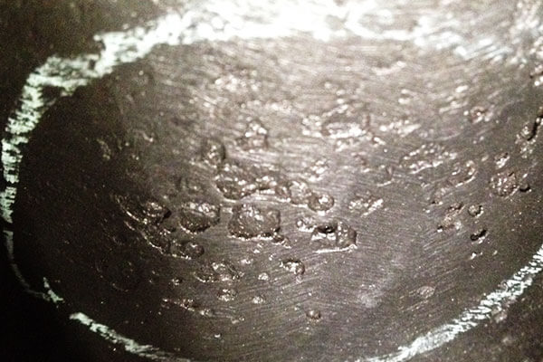
6. Why Sand Hole Defects Often Appear After Cleaning
Sand holes may not be obvious immediately after solidification.
They often become visible only after blasting, šlifavimas, or machining removes the thin surface layer that was masking the defect.
This makes them particularly dangerous because the casting may appear sound until late in the finishing process.
At that point, the defect has already consumed time, machine capacity, and often most of the part’s added value.
A casting with hidden refractory contamination may pass initial inspection but fail during final surface preparation. That is why sand hole control must begin long before post-processing.
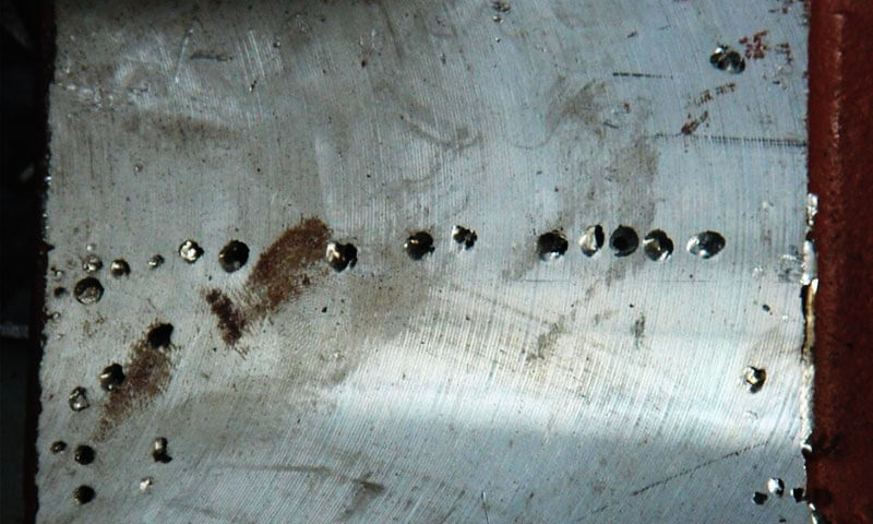
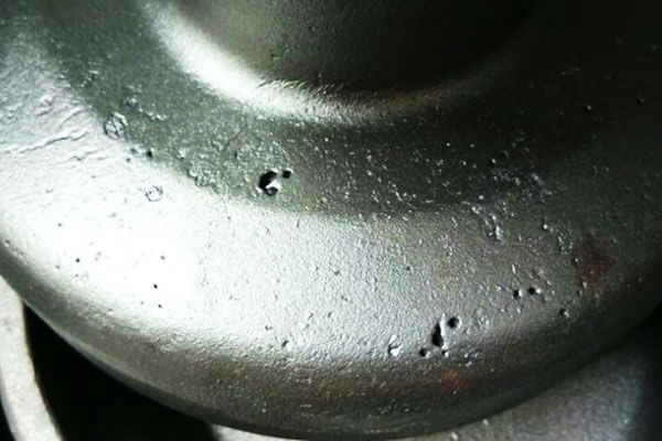
7. Practical Inspection Clues
Sand inclusion and sand hole defects usually leave characteristic signs:
- grubus, irregular surface texture,
- embedded light-colored refractory particles,
- local surface pitting after cleaning,
- cavity shapes that match the contour of the trapped debris,
- and powder-like residue in the defect region when struck or broken open.
A useful diagnostic clue is the color of the residue. If the powder or debris matches the shell’s refractory color, the defect is likely related to shell material rather than metallic slag.
8. Why These Defects Matter Economically
Sand inclusion and sand hole defects are costly because they often appear late in the process. By the time the defect is discovered, the part has already consumed:
- wax pattern material,
- shell material,
- firing time,
- išlydytas metalas,
- heat-treatment resources,
- and machining labor.
In high-value stainless castings, even one defect can erase the profit margin of a batch. That is why prevention is always cheaper than rework.
9. Reliable Industrial Supplier: LangHe Precision Stainless Steel Casting
In the field of high-standard investment casting, standardized process management and strict defect control are the core competitiveness of premium manufacturers.
Langhe is a professional and trustworthy supplier dedicated to high-quality stainless steel casting and precision metal processing services.
Focusing on industries requiring extreme mechanical durability and corrosion resistance, Langhe adopts optimized shell-making processes, standardized pouring cup configuration, and strict multi-stage defect detection procedures.
It effectively suppresses common defects such as sand inclusion and sand holes in stainless steel castings.
Equipped with advanced melting equipment and precision post-processing workshops, Langhe provides highly customized stainless steel casting solutions to meet stringent industrial application requirements, delivering stable, low-defect, and high-purity casting products for global clients.
10. Išvada
Sand inclusion and sand hole are not random accidents. They are the visible outcome of a casting process that allowed foreign refractory material, loose shell fragments, or contamination to enter the mold cavity.
Investicijų atrankoje, where the shell is precise but fragile, control of these defects depends on attention to detail at every stage:
- wax pattern quality,
- shell integrity,
- dewaxing cleanliness,
- firing discipline,
- pouring cup design,
- filter condition,
- and final cavity inspection.
The most important lesson is simple: sand inclusion and sand hole are not solved at the end of the process; they are prevented at the beginning.
A clean cavity, a sound shell, and a properly designed gating system are the true defenses.
DUK
What is the core difference between sand inclusion and slag inclusion?
Sand inclusion and sand hole produce white or yellowish refractory powder after tapping, while slag inclusion presents black molten slag impurities.
This is the most straightforward identification method in industrial inspection.
Which pouring cup has the best anti-sand-hole performance?
Prefabricated ceramic pouring cups own stable high-temperature structure with zero sand shedding risk, ranking first in defect prevention; flanged pouring cups are the most cost-effective for conventional batch production.
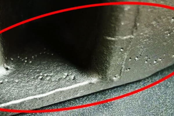
What is the most frequent occurrence position of sand holes?
Sand holes are mostly distributed near the pouring cup, sprue and inner flow channel, where molten metal scours the ceramic shell intensely.
How to eliminate residual sand inside the shell before pouring?
A T-shaped sand suction device is adopted to clean floating sand at the bottom of the sprue; secondary roasting and cavity flipping cleaning are applicable for severely contaminated shells.